National Instruments Module Scxi 1125 Users Manual User
SCXI-1125 to the manual 546db066-d660-4226-b8dc-b7c631d7867e
2015-02-05
: National-Instruments National-Instruments-Module-Scxi-1125-Users-Manual-493748 national-instruments-module-scxi-1125-users-manual-493748 national-instruments pdf
Open the PDF directly: View PDF ![]() .
.
Page Count: 101 [warning: Documents this large are best viewed by clicking the View PDF Link!]
- SCXI-1125 User Manual
- Support
- Important Information
- Conventions
- Contents
- Chapter 1 About the SCXI-1125
- What You Need to Get Started
- National Instruments Documentation
- Installing Application Software, NI-DAQ, and the DAQ Device
- Installing the SCXI-1125 Module into the SCXI Chassis
- Connecting the SCXI-1125 in an SCXI Chassis to an E/M Series DAQ Device for Multiplexed Scanning
- Connecting the SCXI-1125 in a PXI/SCXI Combination Chassis to an E/M Series DAQ Device for Multiplexed Scanning
- Connecting the SCXI-1125 to a n E/M Series DAQ Device for Parallel Scanning
- Verifying the SCXI-1125 Installation in Software
- Troubleshooting the Self-Test Verification
- Chapter 2 Connecting Signals
- Chapter 3 Configuring and Testing
- Chapter 4 Theory of Operation
- Chapter 5 Using the SCXI-1125
- Temperature Measurements Using Thermocouples
- Making High-Voltage Measurements
- Developing Your Application in NI-DAQmx
- Developing Your Application in Traditional NI-DAQ (Legacy)
- Traditional NI-DAQ (Legacy) in LabVIEW
- Configure the SCXI-1125 Settings Using Traditional NI-DAQ (Legacy) in LabVIEW
- Configure, Start Acquisition, and Take Readings Using Traditional NI-DAQ (Legacy) in LabVIEW
- Convert Scaling Using Traditional NI-DAQ (Legacy) in LabVIEW
- Analyze and Display Using Traditional NI-DAQ (Legacy) in LabVIEW
- Traditional NI-DAQ (Legacy) in Text-Based ADEs
- Configuring System Settings Using Traditional NI-DAQ (Legacy) C API
- Configure Module Settings Using Traditional NI-DAQ (Legacy) C API
- Perform Offset Null Compensation Using Traditional NI-DAQ (Legacy) C API
- Perform Acquisition Using Traditional NI-DAQ (Legacy) C API
- Perform Scaling, Analysis, and Display
- Using Software for Multiplexed Scanning
- Performing a Multiplexed Scan
- Using Software for Parallel Scanning
- Other Application Documentation and Material
- Calibration
- Appendix A Specifications
- Appendix B Using SCXI Channel Strings with Traditional NI-DAQ (Legacy) 7.0 or Later
- Appendix C Removing the SCXI-1125
- Appendix D Common Questions
- Glossary
- Index

SCXITM
SCXI-1125 User Manual
SCXI-1125 User Manual
April 2008
372425B-01
Support
Worldwide Technical Support and Product Information
ni.com
National Instruments Corporate Headquarters
11500 North Mopac Expressway Austin, Texas 78759-3504 USA Tel: 512 683 0100
Worldwide Offices
Australia 1800 300 800, Austria 43 662 457990-0, Belgium 32 (0) 2 757 0020, Brazil 55 11 3262 3599,
Canada 800 433 3488, China 86 21 5050 9800, Czech Republic 420 224 235 774, Denmark 45 45 76 26 00,
Finland 358 (0) 9 725 72511, France 01 57 66 24 24, Germany 49 89 7413130, India 91 80 41190000,
Israel 972 3 6393737, Italy 39 02 41309277, Japan 0120-527196, Korea 82 02 3451 3400,
Lebanon 961 (0) 1 33 28 28, Malaysia 1800 887710, Mexico 01 800 010 0793, Netherlands 31 (0) 348 433 466,
New Zealand 0800 553 322, Norway 47 (0) 66 90 76 60, Poland 48 22 3390150, Portugal 351 210 311 210,
Russia 7 495 783 6851, Singapore 1800 226 5886, Slovenia 386 3 425 42 00, South Africa 27 0 11 805 8197,
Spain 34 91 640 0085, Sweden 46 (0) 8 587 895 00, Switzerland 41 56 2005151, Taiwan 886 02 2377 2222,
Thailand 662 278 6777, Turkey 90 212 279 3031, United Kingdom 44 (0) 1635 523545
For further support information, refer to the Signal Conditioning Technical Support Information document.
To comment on National Instruments documentation, refer to the National Instruments Web site at
ni.com/info and enter the info code feedback.
© 1999–2008 National Instruments Corporation. All rights reserved.

Important Information
Warranty
The SCXI-1125 is warranted against defects in materials and workmanship for a period of one year from the date of shipment, as evidenced
by receipts or other documentation. National Instruments will, at its option, repair or replace equipment that proves to be defective during the
warranty period. This warranty includes parts and labor.
The media on which you receive National Instruments software are warranted not to fail to execute programming instructions, due to defects in
materials and workmanship, for a period of 90 days from date of shipment, as evidenced by receipts or other documentation. National Instruments
will, at its option, repair or replace software media that do not execute programming instructions if National Instruments receives notice of such defects
during the warranty period. National Instruments does not warrant that the operation of the software shall be uninterrupted or error free.
A Return Material Authorization (RMA) number must be obtained from the factory and clearly marked on the outside of the package before any
equipment will be accepted for warranty work. National Instruments will pay the shipping costs of returning to the owner parts which are covered by
warranty.
National Instruments believes that the information in this document is accurate. The document has been carefully reviewed for technical accuracy. In
the event that technical or typographical errors exist, National Instruments reserves the right to make changes to subsequent editions of this document
without prior notice to holders of this edition. The reader should consult National Instruments if errors are suspected. In no event shall National
Instruments be liable for any damages arising out of or related to this document or the information contained in it.
EXCEPT AS SPECIFIED HEREIN, NATIONAL INSTRUMENTS MAKES NO WARRANTIES, EXPRESS OR IMPLIED, AND SPECIFICALLY DISCLAIMS ANY WARRANTY OF
MERCHANTABILITY OR FITNESS FOR A PARTICULAR PURPOSE. CUSTOMER’S RIGHT TO RECOVER DAMAGES CAUSED BY FAULT OR NEGLIGENCE ON THE PART OF NATIONAL
INSTRUMENTS SHALL BE LIMITED TO THE AMOUNT THERETOFORE PAID BY THE CUSTOMER. NATIONAL INSTRUMENTS WILL NOT BE LIABLE FOR DAMAGES RESULTING
FROM LOSS OF DATA, PROFITS, USE OF PRODUCTS, OR INCIDENTAL OR CONSEQUENTIAL DAMAGES, EVEN IF ADVISED OF THE POSSIBILITY THEREOF. This limitation of
the liability of National Instruments will apply regardless of the form of action, whether in contract or tort, including negligence. Any action against
National Instruments must be brought within one year after the cause of action accrues. National Instruments shall not be liable for any delay in
performance due to causes beyond its reasonable control. The warranty provided herein does not cover damages, defects, malfunctions, or service
failures caused by owner’s failure to follow the National Instruments installation, operation, or maintenance instructions; owner’s modification of the
product; owner’s abuse, misuse, or negligent acts; and power failure or surges, fire, flood, accident, actions of third parties, or other events outside
reasonable control.
Copyright
Under the copyright laws, this publication may not be reproduced or transmitted in any form, electronic or mechanical, including photocopying,
recording, storing in an information retrieval system, or translating, in whole or in part, without the prior written consent of National
Instruments Corporation.
National Instruments respects the intellectual property of others, and we ask our users to do the same. NI software is protected by copyright and other
intellectual property laws. Where NI software may be used to reproduce software or other materials belonging to others, you may use NI software only
to reproduce materials that you may reproduce in accordance with the terms of any applicable license or other legal restriction.
Trademarks
National Instruments, NI, ni.com, and LabVIEW are trademarks of National Instruments Corporation. Refer to the Terms of Use section
on ni.com/legal for more information about National Instruments trademarks.
Other product and company names mentioned herein are trademarks or trade names of their respective companies.
Members of the National Instruments Alliance Partner Program are business entities independent from National Instruments and have no
agency, partnership, or joint-venture relationship with National Instruments.
Patents
For patents covering National Instruments products, refer to the appropriate location: Help»Patents in your software, the patents.txt file
on your media, or ni.com/patents.
WARNING REGARDING USE OF NATIONAL INSTRUMENTS PRODUCTS
(1) NATIONAL INSTRUMENTS PRODUCTS ARE NOT DESIGNED WITH COMPONENTS AND TESTING FOR A LEVEL OF
RELIABILITY SUITABLE FOR USE IN OR IN CONNECTION WITH SURGICAL IMPLANTS OR AS CRITICAL COMPONENTS IN
ANY LIFE SUPPORT SYSTEMS WHOSE FAILURE TO PERFORM CAN REASONABLY BE EXPECTED TO CAUSE SIGNIFICANT
INJURY TO A HUMAN.
(2) IN ANY APPLICATION, INCLUDING THE ABOVE, RELIABILITY OF OPERATION OF THE SOFTWARE PRODUCTS CAN BE
IMPAIRED BY ADVERSE FACTORS, INCLUDING BUT NOT LIMITED TO FLUCTUATIONS IN ELECTRICAL POWER SUPPLY,
COMPUTER HARDWARE MALFUNCTIONS, COMPUTER OPERATING SYSTEM SOFTWARE FITNESS, FITNESS OF COMPILERS
AND DEVELOPMENT SOFTWARE USED TO DEVELOP AN APPLICATION, INSTALLATION ERRORS, SOFTWARE AND HARDWARE
COMPATIBILITY PROBLEMS, MALFUNCTIONS OR FAILURES OF ELECTRONIC MONITORING OR CONTROL DEVICES,
TRANSIENT FAILURES OF ELECTRONIC SYSTEMS (HARDWARE AND/OR SOFTWARE), UNANTICIPATED USES OR MISUSES, OR
ERRORS ON THE PART OF THE USER OR APPLICATIONS DESIGNER (ADVERSE FACTORS SUCH AS THESE ARE HEREAFTER
COLLECTIVELY TERMED “SYSTEM FAILURES”). ANY APPLICATION WHERE A SYSTEM FAILURE WOULD CREATE A RISK OF
HARM TO PROPERTY OR PERSONS (INCLUDING THE RISK OF BODILY INJURY AND DEATH) SHOULD NOT BE RELIANT SOLELY
UPON ONE FORM OF ELECTRONIC SYSTEM DUE TO THE RISK OF SYSTEM FAILURE. TO AVOID DAMAGE, INJURY, OR DEATH,
THE USER OR APPLICATION DESIGNER MUST TAKE REASONABLY PRUDENT STEPS TO PROTECT AGAINST SYSTEM FAILURES,
INCLUDING BUT NOT LIMITED TO BACK-UP OR SHUT DOWN MECHANISMS. BECAUSE EACH END-USER SYSTEM IS
CUSTOMIZED AND DIFFERS FROM NATIONAL INSTRUMENTS' TESTING PLATFORMS AND BECAUSE A USER OR APPLICATION
DESIGNER MAY USE NATIONAL INSTRUMENTS PRODUCTS IN COMBINATION WITH OTHER PRODUCTS IN A MANNER NOT
EVALUATED OR CONTEMPLATED BY NATIONAL INSTRUMENTS, THE USER OR APPLICATION DESIGNER IS ULTIMATELY
RESPONSIBLE FOR VERIFYING AND VALIDATING THE SUITABILITY OF NATIONAL INSTRUMENTS PRODUCTS WHENEVER
NATIONAL INSTRUMENTS PRODUCTS ARE INCORPORATED IN A SYSTEM OR APPLICATION, INCLUDING, WITHOUT
LIMITATION, THE APPROPRIATE DESIGN, PROCESS AND SAFETY LEVEL OF SUCH SYSTEM OR APPLICATION.

Conventions
The following conventions are used in this manual:
< > Angle brackets that contain numbers separated by an ellipsis represent a
range of values associated with a bit or signal name—for example,
P0.<3..0>.
»The » symbol leads you through nested menu items and dialog box options
to a final action. The sequence File»Page Setup»Options directs you to
pull down the File menu, select the Page Setup item, and select Options
from the last dialog box.
This icon denotes a note, which alerts you to important information.
This icon denotes a caution, which advises you of precautions to take to
avoid injury, data loss, or a system crash. When this symbol is marked on a
product, refer to the Read Me First: Safety and Radio-Frequency
Interference for information about precautions to take.
When symbol is marked on a product, it denotes a warning advising you to
take precautions to avoid electrical shock.
When symbol is marked on a product it, denotes a component that may be
hot. Touching this component may result in bodily injury.
bold Bold text denotes items that you must select or click in the software, such
as menu items and dialog box options. Bold text also denotes parameter
names.
italic Italic text denotes variables, emphasis, a cross-reference, or an introduction
to a key concept. Italic text also denotes text that is a placeholder for a word
or value that you must supply.
monospace Text in this font denotes text or characters that you should enter from the
keyboard, sections of code, programming examples, and syntax examples.
This font is also used for the proper names of disk drives, paths, directories,
programs, subprograms, subroutines, device names, functions, operations,
variables, filenames, and extensions.
monospace bold Bold text in this font denotes the messages and responses that the computer
automatically prints to the screen. This font also emphasizes lines of code
that are different from the other examples.
monospace italic
Italic text in this font denotes text that is a placeholder for a word or value
that you must supply.

© National Instruments Corporation v SCXI-1125 User Manual
Contents
Chapter 1
About the SCXI-1125
What You Need to Get Started ......................................................................................1-1
National Instruments Documentation ............................................................................1-2
Installing Application Software, NI-DAQ, and the DAQ Device .................................1-4
Installing the SCXI-1125 Module into the SCXI Chassis...............................1-4
Connecting the SCXI-1125 in an SCXI Chassis
to an E/M Series DAQ Device for Multiplexed Scanning ...........................1-4
Connecting the SCXI-1125 in a PXI/SCXI Combination Chassis
to an E/M Series DAQ Device for Multiplexed Scanning ...........................1-4
Connecting the SCXI-1125 to a n E/M Series DAQ Device
for Parallel Scanning ....................................................................................1-5
Verifying the SCXI-1125 Installation in Software ........................................................1-5
Installing SCXI Using NI-DAQmx in Software .............................................1-5
Manually Adding Modules in NI-DAQmx .....................................................1-6
Installing SCXI Using Traditional NI-DAQ (Legacy) in Software ................1-6
Manually Adding Modules in Traditional NI-DAQ (Legacy) ........................1-6
Verifying and Self-Testing the Installation .....................................................1-6
Troubleshooting the Self-Test Verification ...................................................................1-7
Troubleshooting in NI-DAQmx ......................................................................1-7
Chapter 2
Connecting Signals
AC and DC Voltage Connections..................................................................................2-1
Ground-Referenced Signal ..............................................................................2-2
Floating Signal.................................................................................................2-3
AC-Coupling ...................................................................................................2-4
Pin Assignments ............................................................................................................2-5
Temperature Sensor Connection .....................................................................2-7
Rear Signal Connector.....................................................................................2-7
Contents
SCXI-1125 User Manual vi ni.com
Chapter 3
Configuring and Testing
SCXI-1125 Software-Configurable Settings ................................................................. 3-1
Common Software-Configurable Settings ...................................................... 3-1
Filter Bandwidth ............................................................................... 3-1
Gain/Input Range.............................................................................. 3-1
Connecting the SCXI-1125 in an SCXI Chassis
to an E/M Series DAQ Device for Multiplexed Scanning........................... 3-2
Connecting the SCXI-1125 in a PXI/SCXI Combination Chassis
to an E/M Series DAQ Device for Multiplexed Scanning........................... 3-2
Configurable Settings in MAX...................................................................................... 3-2
NI-DAQmx ..................................................................................................... 3-3
Creating a Voltage Global Channel or Task..................................... 3-3
Traditional NI-DAQ (Legacy) ........................................................................ 3-4
Configuring Module Property Pages
in Traditional NI-DAQ (Legacy)................................................... 3-5
Creating a Virtual Channel ............................................................... 3-6
Verifying the Signal ...................................................................................................... 3-6
Verifying the Signal in NI-DAQmx Using a Task or Global Channel........... 3-6
Verifying the Signal in Traditional NI-DAQ (Legacy) .................................. 3-7
Verifying the Signal Using Channel Strings .................................... 3-7
Verifying the Signal Using Virtual Channel .................................... 3-8
Chapter 4
Theory of Operation
Gain ............................................................................................................................... 4-1
Filter Bandwidth and Cutoff Frequency........................................................................ 4-2
Operating in Multiplexed Mode .................................................................................... 4-2
Multiplexed Hardware Operation Theory....................................................... 4-3
Operating in Parallel Mode ........................................................................................... 4-3
Theory of Parallel Hardware Operation.......................................................... 4-4
Chapter 5
Using the SCXI-1125
Temperature Measurements Using Thermocouples...................................................... 5-1
Making High-Voltage Measurements ........................................................................... 5-4
Developing Your Application in NI-DAQmx............................................................... 5-5
Typical Program Flowchart ............................................................................ 5-5
General Discussion of Typical Flowchart....................................................... 5-7
Creating a Task Using DAQ Assistant or Programmatically ........... 5-7
Adjusting Timing and Triggering..................................................... 5-7
Contents
© National Instruments Corporation vii SCXI-1125 User Manual
Configuring Channel Properties........................................................5-8
Acquiring, Analyzing, and Presenting ..............................................5-9
Completing the Application ..............................................................5-9
Developing an Application Using LabVIEW..................................................5-9
Using a DAQmx Channel Property Node in LabVIEW ...................5-11
Specifying Channel Strings in NI-DAQmx.....................................................5-12
Text Based ADEs..............................................................................5-14
Measurement Studio (Visual Basic, .NET, and C#)........................................5-14
Programmable NI-DAQmx Properties..............................................5-14
Developing Your Application in Traditional NI-DAQ (Legacy) ..................................5-15
Traditional NI-DAQ (Legacy) in LabVIEW...................................................5-16
Typical Program Flow ......................................................................5-17
Configure the SCXI-1125 Settings Using Traditional NI-DAQ
(Legacy) in LabVIEW ..................................................................................5-18
Configure, Start Acquisition, and Take Readings Using Traditional
NI-DAQ (Legacy) in LabVIEW...................................................................5-19
Convert Scaling Using Traditional NI-DAQ (Legacy) in LabVIEW .............5-20
Analyze and Display Using Traditional NI-DAQ (Legacy) in LabVIEW......5-20
Traditional NI-DAQ (Legacy) in Text-Based ADEs ......................................5-21
Configuring System Settings Using Traditional NI-DAQ (Legacy) C API....5-21
Configure Module Settings Using Traditional NI-DAQ (Legacy) C API ......5-22
Perform Offset Null Compensation
Using Traditional NI-DAQ (Legacy) C API ................................................5-23
Perform Acquisition Using Traditional NI-DAQ (Legacy) C API .................5-23
Perform Scaling, Analysis, and Display..........................................................5-24
Using Software for Multiplexed Scanning ......................................................5-24
LabVIEW and the SCXI Channel String ..........................................5-25
LabVIEW and the Virtual Channel String........................................5-26
Performing a Multiplexed Scan.......................................................................5-27
C and Low-Level DAQ Functions ....................................................5-28
Using Software for Parallel Scanning .............................................................5-28
LabVIEW and Parallel Mode............................................................5-28
C and Parallel Mode..........................................................................5-29
Other Application Documentation and Material ...........................................................5-29
Traditional NI-DAQ (Legacy) CVI Examples ................................................5-29
Traditional NI-DAQ (Legacy) Measurement Studio Examples......................5-29
Calibration .....................................................................................................................5-30
Calibration Procedures ....................................................................................5-30
One-Point Offset Calibration ............................................................5-31
Two-Point Gain and Offset Calibration ............................................5-32
Contents
SCXI-1125 User Manual viii ni.com
Appendix A
Specifications
Appendix B
Using SCXI Channel Strings with Traditional NI-DAQ (Legacy) 7.0
or Later
Appendix C
Removing the SCXI-1125
Appendix D
Common Questions
Glossary
Index
Figures
Figure 2-1. Connecting a Ground-Referenced Signal ............................................. 2-2
Figure 2-2. Connecting a Floating Signal................................................................ 2-3
Figure 2-3. Connecting a Floating AC-Coupled Signal .......................................... 2-4
Figure 2-4. Connecting a Ground-Referenced AC-Coupled Signal ........................ 2-4
Figure 4-1. SCXI-1125 Block Diagram................................................................... 4-1
Figure 5-1. Typical Program Flowchart .................................................................. 5-6
Figure 5-2. LabVIEW Channel Property Node with Lowpass Frequency
Set at 10 kHz on Channel SC1Mod1/ai0 .............................................. 5-12
Figure 5-3. Typical SCXI-1125 Program Flow
with Traditional NI-DAQ (Legacy) ...................................................... 5-17
Figure 5-4. Using the AI Parameter VI to Set Up the SCXI-1125 .......................... 5-19
Figure A-1. SCXI-1125 Dimensions ........................................................................ A-7
Figure C-1. Removing the SCXI-1125..................................................................... C-2
Contents
© National Instruments Corporation ix SCXI-1125 User Manual
Tables
Table 2-1. Front Signal Pin Assignments ..............................................................2-6
Table 2-2. Rear Signal Pin Assignments ................................................................2-8
Table 5-1. Extended Gain and Range Using the SCXI-1327 or SCXI-1313A.......5-4
Table 5-2. Extended Gain and Range Using the TBX-1316 ..................................5-5
Table 5-3. NI-DAQmx Properties ..........................................................................5-8
Table 5-4. Programming a Task in LabVIEW........................................................5-10
Table 5-5. NI-DAQmx Properties ..........................................................................5-15
Table 5-6. Settings for Configuring the SCXI-1125
Through the AI Parameter.....................................................................5-18
Table 5-7. Configuration Functions........................................................................5-22
Table 5-8. NI-DAQ Functions Used to Configure SCXI-1125 ..............................5-23
Table 5-9. Gain Values and Input Limits ..............................................................5-31
Table A-1. Input Signal Range Versus Gain ...........................................................A-1
Table A-2. Terminal Block Maximum Voltages.....................................................A-8
Table D-1. Comparison of the SCXI-1125 with the SCXI-1120 ............................D-1
Table D-2. Digital Signals on the SCXI-1125.........................................................D-3

© National Instruments Corporation 1-1 SCXI-1125 User Manual
1
About the SCXI-1125
This chapter introduces the SCXI-1125 module and explains how to install
the software and hardware.
The SCXI-1125 is an eight-channel isolated analog input conditioning
module with programmable gain and filter settings on each channel and
is jumperless. Each channel has 12 programmable gain settings from
1 to 2000 and two programmable filter settings of either 4 Hz or 10 kHz.
Each channel has an external circuit for grounding the inputs that you can
use for offset calibration. An onboard EEPROM provides nonvolatile
storage of software correction constants for both gain and offset.
The SCXI-1125 provides up to 300 Vrms working isolation per channel and
has an input range of up to 1000 VDC when using an appropriate attenuator
terminal block. The SCXI-1125 supports both multiplexed and parallel
output modes and includes a cold-junction compensation (CJC) channel
that you can scan in multiplexed mode.
What You Need to Get Started
To set up and use the SCXI-1125 module, you need the following:
❑Hardware
– SCXI-1125 module
– One of the following terminal blocks:
• SCXI-1305
• SCXI-1313A
• SCXI-1320
• SCXI-1327
• SCXI-1328
• SCXI-1338
• TBX-1316
• TBX-1328
• TBX-1329

Chapter 1 About the SCXI-1125
SCXI-1125 User Manual 1-2 ni.com
Note For maximum allowable voltage for a particular terminal block refer to Table A-2,
Terminal Block Maximum Voltages.
– SCXI or PXI/SCXI combination chassis
– One of the following:
• E/M Series DAQ device
• SCXI-1600 module
– A computer if using an SCXI chassis
– Cabling, cable adapter, and sensors as required for your
application
❑Software
– NI-DAQ 7.0 or later
– One of the following software packages:
•LabVIEW
• LabWindows™/CVI™
• Measurement Studio
❑Documentation
–Read Me First: Safety and Radio-Frequency Interference
–DAQ Getting Started Guide
–SCXI Quick Start Guide
–SCXI-1125 User Manual
– Documentation for your hardware
– Documentation for your software
National Instruments Documentation
The SCXI-1125 User Manual is one piece of the documentation set for data
acquisition (DAQ) systems. You could have any of several types of
manuals depending on the hardware and software in the system. Use the
manuals you have as follows:
• SCXI or PXI chassis manual—Read this manual for maintenance
information on the chassis and for installation instructions.
• The DAQ Getting Started Guide—This document has information on
installing NI-DAQ and the E/M Series DAQ device. Install these
before you install the SCXI module.
Chapter 1 About the SCXI-1125
© National Instruments Corporation 1-3 SCXI-1125 User Manual
• The SCXI Quick Start Guide—This document contains a quick
overview for setting up an SCXI chassis, installing SCXI modules and
terminal blocks, and attaching sensors. It also describes setting up the
SCXI system in MAX.
• The SCXI hardware user manuals—Read these manuals next
for detailed information about signal connections and module
configuration. They also explain, in greater detail, how the module
works and contain application hints.
• Accessory installation guides or manuals—If you are using accessory
products, read the terminal block and cable assembly installation
guides. They explain how to physically connect the relevant pieces
of the system. Consult these guides when you are making the
connections.
• The E/M Series DAQ device documentation—This documentation has
detailed information about the E/M Series DAQ device that plugs into
or is connected to the computer. Use this documentation for hardware
installation and configuration instructions, specification information
about the E/M Series DAQ device, and application hints.
• Software documentation—You may have both application software
and NI-DAQ software documentation. National Instruments (NI)
application software includes LabVIEW, LabWindows/CVI, and
Measurement Studio. After you set up the hardware system, use either
your application software documentation or the NI-DAQ
documentation to help you write your application. If you have a large,
complex system, it is worthwhile to look through the software
documentation before you configure the hardware.
• One or more of the following help files for software information:
–Start»Programs»National Instruments»NI-DAQ»
NI-DAQmx Help
–Start»Programs»National Instruments»NI-DAQ»
Traditional NI-DAQ User Manual
–Start»Programs»National Instruments»NI-DAQ»
Traditional NI-DAQ Function Reference Help
• NI application notes or tutorials—NI has additional material on
measurements available at ni.com/support.
You can download NI documents from ni.com/manuals. To download
the latest version of NI-DAQ, click Drivers and Updates at ni.com.

Chapter 1 About the SCXI-1125
SCXI-1125 User Manual 1-4 ni.com
Installing Application Software, NI-DAQ, and the
DAQ Device
Refer to the DAQ Getting Started Guide packaged with the NI-DAQ
software to install your application software, NI-DAQ driver software, and
the DAQ device to which you will connect the SCXI-1125. NI-DAQ 7.0 or
later is required to configure and program the SCXI-1125 module. If you
do not have NI-DAQ 7.0 or later, you can either contact a NI sales
representative to request it on a CD or download the latest NI-DAQ version
from ni.com.
Note Refer to the Read Me First: Safety and Radio-Frequency Interference document
before removing equipment covers or connecting or disconnecting any signal wires.
Installing the SCXI-1125 Module into the SCXI Chassis
Refer to the SCXI Quick Start Guide to install your SCXI-1125 module.
Connecting the SCXI-1125 in an SCXI Chassis to an E/M Series
DAQ Device for Multiplexed Scanning
Refer to the SCXI Quick Start Guide to install the cable adapter and connect
the SCXI modules to the DAQ device.
If you have already installed the appropriate software, refer to Chapter 3,
Configuring and Testing, to configure the SCXI-1125 module(s).
Connecting the SCXI-1125 in a PXI/SCXI Combination Chassis to an
E/M Series DAQ Device for Multiplexed Scanning
Refer to the SCXI Quick Start Guide to connect the SCXI modules to the
DAQ device.
If you have already installed the appropriate software, refer to Chapter 3,
Configuring and Testing, to configure the SCXI-1125 module(s).

Chapter 1 About the SCXI-1125
© National Instruments Corporation 1-5 SCXI-1125 User Manual
Connecting the SCXI-1125 to a n E/M Series DAQ Device for
Parallel Scanning
This configuration allows you to route all eight channels of the SCXI-1125
in parallel to eight input channels of the E/M Series DAQ device to which
it is connected. In this mode, you cannot directly access the CJC channel.
Use this mode if you require a higher scanning rate than an SCXI system in
multiplexed mode allows.
If you have not already installed all the modules, refer to the Installing the
SCXI-1125 Module into the SCXI Chassis section, then complete the
following steps:
1. Power off the SCXI chassis and the computer that contains the
E/M Series DAQ device.
2. Insert the cable adapter into the rear of the SCXI-1125 module that is
to be accessed in parallel mode by the E/M Series DAQ device. Refer
to the installation guide for the cable assembly for more information.
3. Connect the cable to the back of the cable adapter ensuring that the
cable fits securely.
4. Connect the other end of the cable to the E/M Series DAQ device that
you want to use to access the SCXI-1125 in parallel mode.
5. Connect additional SCXI-1125 modules intended for parallel mode
operation by repeating steps 2 through 4.
6. Check the installation, making sure the cable is securely fastened at
both ends.
7. Power on the SCXI chassis.
8. Power on the computer.
If you have already installed the appropriate software, you are ready to
configure the SCXI-1125 module(s) you installed for parallel mode
operation.
Verifying the SCXI-1125 Installation in Software
Refer to the SCXI Quick Start Guide for information on verifying the SCXI
installation.
Installing SCXI Using NI-DAQmx in Software
Refer to the SCXI Quick Start Guide for information on installing modules
using NI-DAQmx in software.

Chapter 1 About the SCXI-1125
SCXI-1125 User Manual 1-6 ni.com
Manually Adding Modules in NI-DAQmx
If you did not auto-detect the SCXI modules, you must manually add each
of the modules. Refer to the SCXI Quick Start Guide to manually add
modules.
Note NI recommends auto-detecting modules for the first time configuration of the
chassis.
Installing SCXI Using Traditional NI-DAQ (Legacy) in Software
Refer to the SCXI Quick Start Guide for information on installing modules
using Traditional NI-DAQ (Legacy) in software.
Manually Adding Modules in Traditional NI-DAQ (Legacy)
If you did not auto-detect the SCXI modules, you must manually add each
of the modules. Refer to the SCXI Quick Start Guide to manually add
modules.
Note NI recommends auto-detecting modules for the first time configuration of the
chassis.
Verifying and Self-Testing the Installation
The verification procedure for the SCXI chassis is the same for both
NI-DAQmx and Traditional NI-DAQ (Legacy). To test the successful
installation for the SCXI chassis, refer to the SCXI Quick Start Guide.
Verify that the chassis is powered on and correctly connected to an
E/M Series DAQ device.
After verifying and self-testing the installation, the SCXI system should
operate properly with your ADE software. If the test did not complete
successfully, refer to Chapter 3, Configuring and Testing, for
troubleshooting steps.

Chapter 1 About the SCXI-1125
© National Instruments Corporation 1-7 SCXI-1125 User Manual
Troubleshooting the Self-Test Verification
If the Self-Test Verification did not verify the chassis configuration,
complete the steps in this section to troubleshoot the SCXI configuration.
Troubleshooting in NI-DAQmx
• If you get a Verify SCXI Chassis message box showing the SCXI
chassis model number, Chassis ID: x, and one or more messages
stating Slot Number: x Configuration has module: SCXI-XXXX
or 1125, hardware in chassis is: Empty, take the following
troubleshooting actions:
– Make sure the SCXI chassis is powered on.
– Make sure all SCXI modules are properly installed in the chassis.
Refer to the SCXI Quick Start Guide for proper installation
instructions.
– Make sure the cable between the SCXI chassis and E/M Series
DAQ device is properly connected.
– Inspect the cable connectors for bent pins.
– Make sure you are using the correct NI cable assembly.
– Test the E/M Series DAQ device to verify it is working properly.
Refer to the E/M Series DAQ device help file for more
information.
• If you get a Verify SCXI Chassis message box showing the SCXI
chassis model number, Chassis ID: x, and the message Slot
Number: x Configuration has module: SCXI-XXXX or 1125,
hardware in chassis is: SCXI-YYYY, 1125, or Empty, complete the
following troubleshooting steps to correct the error.
1. Expand the list of NI-DAQmx devices by clicking the + next to
NI-DAQmx Devices.
2. Right-click the SCXI chassis and click Properties to load the
chassis configurator.
3. Under the Modules tab, ensure that the cabled module is listed in
the correct slot.
4. If the cabled module is not listed in the correct slot, complete the
following troubleshooting steps:
a. If the cabled module is not listed in the correct slot and the
slot is empty, click the drop-down listbox next to the correct
slot and select the cabled module. Configure the cabled
Chapter 1 About the SCXI-1125
SCXI-1125 User Manual 1-8 ni.com
module following the steps listed in the SCXI Quick Start
Guide. Click OK.
b. If another module appears where the cabled module should
be, click the drop-down listbox next to the correct slot and
select the cabled module. A message box appears asking you
to confirm the module replacement. Click OK. Configure the
cabled module following the steps listed in the SCXI Quick
Start Guide. Click OK.
• Ensure that you have the highest priority SCXI module cabled to the
E/M Series DAQ device. Refer to the SCXI Quick Start Guide to find
out which SCXI module in the chassis should be cabled to the
E/M Series DAQ device.
• After checking the preceding items, return to the Troubleshooting the
Self-Test Verification section and retest the SCXI chassis.
If these measures do not successfully configure the SCXI system, contact
NI. Refer to the Signal Conditioning Technical Support Information
document for contact information.

© National Instruments Corporation 2-1 SCXI-1125 User Manual
2
Connecting Signals
This chapter describes the input and output signals connections to the
SCXI-1125 module with the module front connector and the rear signal
connector. This chapter also includes specifications and connection
instructions for the signals on the SCXI-1125 module connectors.
Notes Refer to the Read Me First: Safety and Radio-Frequency Interference document
before removing equipment covers or connecting or disconnecting any signal wires.
For EMC compliance, operate this device with shielded cabling.
The isolated channels of the SCXI-1125 allow you to make precision
high-voltage measurements or low-voltage measurement of signals riding
on high common-mode voltages while protecting sensitive computer parts
and equipment connected to the module. The isolated amplifiers fulfill
two purposes on the SCXI-1125 module. First, they can convert a small
signal riding on a high common-mode voltage into a single-ended signal
with respect to the SCXI-1125 chassis ground. With this conversion, you
can extract the analog input signal from a high common-mode voltage
before sampling by the E/M Series DAQ device. Second, the isolation
amplifier amplifies and filters an input signal resulting in increased
measurement resolution and accuracy. The following sections explain how
to make signal connections to maximize the effectiveness of the
SCXI-1125 for conditioning analog signals.
AC and DC Voltage Connections
You can make input signal connections to the SCXI-1125 through the front
signal connector or through accessory terminal blocks. Chapter 1, About
the SCXI-1125, contains a list of SCXI-1125-compatible terminal blocks.
Terminal blocks have features such as screw-terminal connectivity, BNC
connectivity, cold-junction temperature measurement, and attenuation.
The pin assignment for the SCXI-1125 front signal connector is shown in
Table 2-1. The positive input terminal for each channel is in Column A and
the negative input terminal for each channel is in Column C. Input
connections to each channel are fully floating with respect to ground and
Chapter 2 Connecting Signals
SCXI-1125 User Manual 2-2 ni.com
completely isolated from other channels. You can operate with
common-mode voltage levels up to 300 Vrms.
Figures 2-1 through 2-4 show signal connection methods that give the
highest noise immunity.
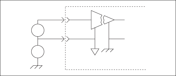
Ground-Referenced Signal
When the negative input signal line is connected either directly or
indirectly to earth ground (usually at the transducer end), connect this line
to the negative input terminal, as shown in Figure 2-1. No ground
connection is made at the SCXI-1125. This situation includes cases where
a floating source can be riding on a high common-mode voltage that is
ground referenced.
Figure 2-1. Connecting a Ground-Referenced Signal
Module
+
–
+
+
+
–
–
I
High
CMV
V
out
V
s
V
cm
Chapter 2 Connecting Signals
© National Instruments Corporation 2-3 SCXI-1125 User Manual
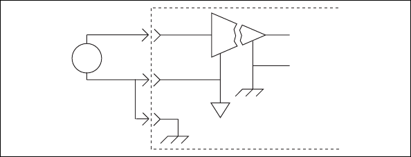
Floating Signal
In cases where both signal lines at the transducer end are floating and no
common-mode voltage exists, establish an earth connection at the
SCXI-1125 by connecting the negative input line to chassis ground in the
terminal block, as shown in Figure 2-2. This eliminates noise that can ride
on the floating signal. If the floating signal is not configured like
Figure 2-2, the noise can couple to the chassis ground through the amplifier
and exhibit a differential mode signal that can be amplified by the
amplifier. Connecting the signal to chassis ground breaks the isolation
barrier.
Figure 2-2. Connecting a Floating Signal
Module
+
–
++
–
I
V
out
V
s
Chapter 2 Connecting Signals
SCXI-1125 User Manual 2-4 ni.com
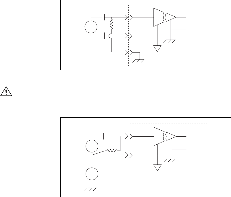
AC-Coupling
You can have an application where you wish to measure only AC voltages
and remove the DC component of a signal before amplification and
sampling. In such cases, you can connect a capacitor in series with one or
both input terminals of the SCXI-1125, as shown in Figures 2-3 and 2-4.
A resistor is connected across the input terminals of the channel to DC
reference the input stage of the SCXI-1125. You do not need to use a bias
resistor with any high-voltage terminal blocks, since the terminal blocks
already have a resistor between the input terminals, or with the SCXI-1305
BNC connectivity terminal block, since this terminal block already has an
AC-coupling option built in.
Figure 2-3. Connecting a Floating AC-Coupled Signal
Caution Connecting a signal source to chassis ground in Figures 2-2 and 2-3, breaks the
isolation barrier.
Figure 2-4. Connecting a Ground-Referenced AC-Coupled Signal
Module
+
–
++
–
I
Vout
VsRbias
Module
+
–
++
–
I
+
–
Rbias
High
CMV
Vout
Vs
Vcm

Chapter 2 Connecting Signals
© National Instruments Corporation 2-5 SCXI-1125 User Manual
The value of the bias resistor should be between 100 kΩ and 1 MΩ . An
added DC offset voltage results, due to input bias current flowing through
the bias resistor. For example, with a 1 MΩ bias resistor and the specified
maximum input bias current of 1 nA, you have a maximum added input
offset voltage of ±1 mV in addition to the initial offset voltage.
Since only the AC signal is of interest when AC-coupling, you can choose
to remove the DC offset in software by using a simple highpass filter.
Caution Pins A2, A4, A8, C2, C4, C6, and C8 on the front signal connector are not isolated
and do not have the same protection circuitry as the positive and negative analog input pairs
discussed in the Floating Signal section. Hooking up external signals to these pins can
damage the SCXI-1125 module.
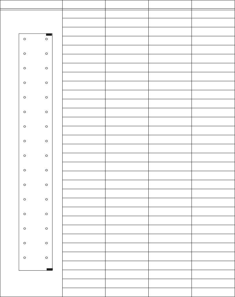
Pin Assignments
The front signal connector is a special 32-pin DIN C male front connector
used for connecting analog input signals, including the CJC, to the analog
circuitry of the SCXI-1125. This connection allows access to the eight
differential analog input signals. The positive terminal is AIx + and the
negative terminal AIx –. A missing pin exists between two consecutive
input channels to meet the UL spacing requirements for high voltage
signals. CJ TEMP is the signal connection used by the cold-junction
channel on the SCXI-1125. The signals on pins A6, A8, C6, and C8 are
reserved for serial communication. The +5 V signal and CHS GND signals
are used as the power supply and ground signals for the CJC sensor and
other circuitry on the terminal block. The pin assignments for the
SCXI-1125 front signal connection are shown in Table 2-1.
Caution Do not make signal connections to pins A2, A4, A6, A8, C2, C4, C6, or C8 on the
front signal connector. Connecting external signals to these pins can damage the
SCXI-1125 Module.
Chapter 2 Connecting Signals
SCXI-1125 User Manual 2-6 ni.com
Table 2-1. Front Signal Pin Assignments
Front Connector Diagram Pin Number Column A Column B Column C
NC means no connection
— means no pin
32 AI 0 + —AI 0 –
31 ———
30 AI 1 + —AI 1 –
29 ———
28 NC —NC
27 ———
26 AI 2 + —AI 2 –
25 ———
24 AI 3 + —AI 3 –
23 ———
22 NC —NC
21 ———
20 AI 4 + —AI 4 –
19 ———
18 AI 5 + —AI 5 –
17 ———
16 NC —NC
15 ———
14 AI 6 + —AI 6 –
13 ———
12 AI 7 + —AI 7 –
11 ———
10 NC —NC
9 — — —
8RSVD —RSVD
7 — — —
6RSVD —RSVD
5 — — —
4+5 V —CJ TEMP
3 — — —
2CHS GND —RSVD
1 — — —
Column
A B C
32
31
30
29
28
27
26
25
24
23
22
21
20
19
18
17
16
15
14
13
12
11
10
9
8
7
6
5
4
3
2
1
Chapter 2 Connecting Signals
© National Instruments Corporation 2-7 SCXI-1125 User Manual
Temperature Sensor Connection
Pin C4 on the front signal connector is used to connect to a terminal block
temperature sensor. The temperature sensor channel is not isolated and is
referenced to the chassis ground. The connection is overvoltage protected
to ±25 VDC with power on and ±15 VDC with power off.
Rear Signal Connector
The rear signal connector is a 50-pin male ribbon cable connector used for
analog signal connectivity and communication between the
SCXI-1125 and the connected DAQ device. The rear signal connector
allows the DAQ device to access all eight differential analog output signals
from the SCXI-1125. The positive terminal of each analog output is
CH x + and the negative terminal CH x –. Grounding signals, AI GND
and OUT REF, provide reference signals needed in the various analog
referencing modes on the E/M Series DAQ device. In multiplexed mode,
the CH 0 signal pair is used for sending all eight channels of the
SCXI-1125, and other analog signals from other modules, to the connected
E/M Series DAQ device. If the module is directly connected to the E/M
Series DAQ device, the other analog channels of the E/M Series DAQ
device are still unavailable for general-purpose analog input because they
are still connected to the amplifier outputs of the SCXI-1125 in multiplexed
mode.
The communication signals between the DAQ device and the SCXI system
are SER DAT IN, SER DAT OUT, DAQ D*/A, SLOT 0 SEL*, SER CLK,
and AI HOLD COMP, AI HOLD. The digital ground, D GND on pins 24
and 33, provides a separate ground reference for the communication
signals. SER DAT IN, SER DAT OUT, DAQ D*/A, SLOT 0 SEL*, and
SER CLK are the communication lines for programming the SCXI-1125.
The AI HOLD COMP, AI HOLD and SYNC signals are the signals
necessary for multiplexed mode scanning. If the E/M Series DAQ device is
connected to the SCXI-1125, these digital lines are unavailable for
general-purpose digital I/O. The rear signal pin assignments are shown in
Table 2-2.

Chapter 2 Connecting Signals
SCXI-1125 User Manual 2-8 ni.com
Table 2-2. Rear Signal Pin Assignments
Rear Connector
Diagram Signal Name Pin Number Pin Number Signal Name
NC means no
connection
AI GND 1 2 AI GND
CH 0 + 3 4 CH 0 –
CH 1 + 5 6 CH 1–
CH 2 + 7 8 CH 2 –
CH 3 + 910 CH 3 –
CH 4 + 11 12 CH 4 –
CH 5 + 13 14 CH 5 –
CH 6 + 15 16 CH 6 –
CH 7 + 17 18 CH 7 –
OUT REF 19 20 NC
NC 21 22 NC
NC 23 24 D GND
SER DAT IN 25 26 SER DAT OUT
DAQ D*/A 27 28 NC
SLOT 0 SEL* 29 30 NC
NC 31 32 NC
D GND 33 34 NC
NC 35 36 AI HOLD COMP, AI HOLD
SER CLK 37 38 NC
NC 39 40 NC
NC 41 42 NC
NC 43 44 NC
NC 45 46 SYNC
NC 47 48 NC
NC 49 50 NC
49 50
47 48
45 46
43 44
41 42
39 40
37 38
35 36
33 34
31 32
29 30
27 28
25 26
23 24
21 22
19 20
17 18
15 16
13 14
11 12
910
78
56
34
12

© National Instruments Corporation 3-1 SCXI-1125 User Manual
3
Configuring and Testing
This chapter discusses configuring the SCXI-1125 in MAX for use with
either NI-DAQmx or Traditional NI-DAQ (Legacy), creating and testing a
virtual channel, global channel or task. For more information on the
relationship between the settings and the measurements and how to
configure settings in your application, refer to Chapter 4, Theory of
Operation.
SCXI-1125 Software-Configurable Settings
This section describes the common software configurable settings and how
to verify the signal using both NI-DAQmx and Traditional NI-DAQ
(Legacy).
Common Software-Configurable Settings
This section describes the most frequently used software-configurable
settings for the SCXI-1125. Refer to Chapter 4, Theory of Operation, for a
complete list of software-configurable settings.
Filter Bandwidth
Filter bandwidth is a software-configurable setting that allows you to select
a lowpass filter cutoff frequency. You can choose 4.0 Hz or 10 kHz.
Gain/Input Range
Gain/input range is a software-configurable setting that allows you to
choose the appropriate amplification to fully utilize the range of the
E/M Series DAQ device. In most applications NI-DAQ chooses and sets
the gain for you determined by the input range.

Chapter 3 Configuring and Testing
SCXI-1125 User Manual 3-2 ni.com
Connecting the SCXI-1125 in an SCXI Chassis to an E/M Series
DAQ Device for Multiplexed Scanning
Refer to the SCXI Quick Start Guide to install the cable adapter and connect
the SCXI modules to the DAQ device.
If you have already installed the appropriate software, refer to Chapter 3,
Configuring and Testing, to configure the SCXI-1125 module(s).
Connecting the SCXI-1125 in a PXI/SCXI Combination Chassis to an
E/M Series DAQ Device for Multiplexed Scanning
Refer to the SCXI Quick Start Guide to connect the SCXI modules to the
DAQ device.
If you have already installed the appropriate software, refer to Chapter 3,
Configuring and Testing, to configure the SCXI-1125 module(s).
Configurable Settings in MAX
Note If you are not using an NI ADE, using an NI ADE prior to version 7.0, or are using
an unlicensed copy of an NI ADE, additional dialog boxes from the NI License Manager
appear allowing you to create a task or global channel in unlicensed mode. These messages
continue to appear until you install version 7.0 or later of an NI ADE.
This section describes where users can access each software-configurable
setting for modification in MAX. The location of the settings varies
depending on the version of NI-DAQ you use. Refer to either the
NI-DAQmx section or the Traditional NI-DAQ (Legacy) section. You also
can refer to the DAQ Getting Started Guide and the SCXI Quick Start Guide
for more information on installing and configuring your hardware. You also
can use the DAQ Assistant to graphically configure common measurement
tasks, channels, or scales.

Chapter 3 Configuring and Testing
© National Instruments Corporation 3-3 SCXI-1125 User Manual
NI-DAQmx
In NI-DAQmx, you can configure software settings such as filter
bandwidth and gain/input signal range in the following ways:
• Task or global channel in MAX
• Functions in your application
Note All software-configurable settings are not configurable both ways. This section only
discusses settings in MAX. Refer to Chapter 4, Theory of Operation, for information on
using functions in your application.
These sections describe settings that you can change in MAX and where
they are located.
• Filter bandwidth—configure the Device tab using either NI-DAQmx
Task or NI-DAQmx Global Channel. You also can set the value
through your application.
• Input signal range—configure the input signal range using either
NI-DAQmx Task or NI-DAQmx Global Channel. When you set the
minimum and maximum range of NI-DAQmx Task or NI-DAQmx
Global Channel, the driver selects the best gain for the measurement.
You also can set it through your application.
• Modes of operation—configure only using chassis installation in
software. Refer to Chapter 1, About the SCXI-1125, for more
information on chassis installation. The default setting in NI-DAQmx
is multiplexed.
• Terminal block attenuation—for terminal blocks with manually
adjustable attenuation such as the SCXI-1327, you must configure the
attenuator in the chassis configurator. Refer to the SCXI Quick Start
Guide for more information.
Note Refer to Chapter 4, Theory of Operation, for information on configuring the settings
for your application using Traditional NI-DAQ (Legacy).
Creating a Voltage Global Channel or Task
To create a new NI-DAQmx global task or channel, complete the following
steps:
1. Double-click Measurement & Automation on the desktop.
2. Right-click Data Neighborhood and select Create New.
3. Select NI-DAQmx Task or NI-DAQmx Global Channel, and click
Next.

Chapter 3 Configuring and Testing
SCXI-1125 User Manual 3-4 ni.com
4. Select Analog Input.
5. Select Voltage.
6. If you are creating a task, you can select a range of channels by holding
down the <Shift> key while selecting the channels. You can select
multiple individual channels by holding down the <Ctrl> key while
selecting channels. If you are creating a channel, you can only select
one channel. Click Next.
7. Name the task or channel and click Finish.
8. In the box labelled Channel List, select the channel(s) you want to
configure. You can select a range of channels by holding down the
<Shift> key while selecting the channels. You can select multiple
individual channels by holding down the <Ctrl> key while selecting
channels.
9. Enter the specific values for your application in the Settings tab.
Context help information for each setting is provided on the right side
of the screen. Refer to Chapter 3, Configuring and Testing, for more
information.
10. Click the Device tab and select the autozero mode and lowpass filter
cutoff frequency.
11. If you are creating a task and want to set timing or triggering controls,
enter the values in the Task Timing and Task Triggering tabs.
Traditional NI-DAQ (Legacy)
In Traditional NI-DAQ (Legacy), you can configure software settings, such
as configuration, voltage excitation level, filter bandwidth, gain/input
signal range, and calibration settings in the following three ways:
• module property pages in MAX
• virtual channels properties in MAX
• functions in your ADE
Note All software-configurable settings are not configurable in all three ways. This
section only discusses settings in MAX. Refer to Chapter 4, Theory of Operation, for
information on using functions in your application.
Most of these settings are available in module properties and/or using
virtual channels:
• Filter bandwidth—configure only using module properties. You also
can set bandwidth through your application. The default filter
bandwidth level for Traditional NI-DAQ (Legacy) is 4 Hz.

Chapter 3 Configuring and Testing
© National Instruments Corporation 3-5 SCXI-1125 User Manual
• Gain/input signal range—configure gain using module properties.
When you set the minimum and maximum range of the virtual
channel, the driver selects the best gain. The default gain setting
for Traditional NI-DAQ (Legacy) is 1000.
• Terminal block gain—this setting is only configurable if you selected
a terminal block that supports adjustable attenuation.
• Modes of operation—configure only using module properties. The
default setting in Traditional NI-DAQ (Legacy) is multiplexed mode.
Note Refer to Chapter 4, Theory of Operation, for information on configuring the settings
for your application using Traditional NI-DAQ (Legacy).
Configuring Module Property Pages in Traditional
NI-DAQ (Legacy)
1. Right-click the SCXI-1125 module you want to configure and select
Properties. Click General.
2. If the module you are configuring is connected to an E Series DAQ
device, select that device by using Connected to. If you want this
E Series DAQ device to control the chassis, confirm there is a check in
the This device will control the chassis checkbox. If the module you
are configuring is not connected to an E Series DAQ device, select
None.
3. Click the Channel tab. Select the appropriate gain and filter for each
channel. If you want to configure all the channels at the same time,
select the Channel drop-down menu, scroll to the bottom, and select
All Channels. Refer to the SCXI-1125 Software-Configurable Settings
section for a detailed description of each setting. Click Apply.
4. Click Accessory. Select the accessory you connected to the module. If
the accessory has a configurable gain, select the desired gain. When
configuration is complete, click OK.
The Traditional NI-DAQ (Legacy) chassis and SCXI-1125 should now be
configured properly. If you need to change the module configuration,
right-click the module and repeat steps 1 through 4. Test the system
following the steps in the Troubleshooting the Self-Test Verification
section of Chapter 1, About the SCXI-1125.

Chapter 3 Configuring and Testing
SCXI-1125 User Manual 3-6 ni.com
Creating a Virtual Channel
To create a virtual channel, complete the following steps:
1. Right-click Data Neighborhood and select Create New.
2. Select Traditional NI-DAQ Virtual Channel and click Finish.
3. Click Add Channel.
4. Select Analog Input from the drop-down list and click Next.
5. Enter the Channel Name and Channel Description, and click Next.
6. Select Voltage from the drop-down list and click Next.
7. Enter the units and input range, and click Next.
8. Select the appropriate scaling option and click Next.
9. Enter the following information:
10. What DAQ hardware will be used? from the drop-down list.
a. What channel on your DAQ hardware? from the drop-down list.
b. Which analog input mode will be used? from the drop-down list.
11. Click Finish.
Verifying the Signal
This section describes how to take measurements using test panels in order
to verify signal, and configuring and installing a system in NI-DAQmx and
Traditional NI-DAQ (Legacy).
Verifying the Signal in NI-DAQmx Using a Task or Global Channel
You can verify the signals on the SCXI-1125 using NI-DAQmx by
completing the following steps:
1. Expand Data Neighborhood.
2. Expand NI-DAQmx Tasks.
3. Click the task.
4. Click the Add Channels or Remove Channels button to add/remove
channels.
5. In the window that appears, click the + next to the module of interest.
6. Select the channel(s) you want to verify. You can select a block of
channels by holding down the <Shift> key or multiple channels by
holding down the <Ctrl> key. Click OK.
7. Enter the appropriate information on the Settings tab.

Chapter 3 Configuring and Testing
© National Instruments Corporation 3-7 SCXI-1125 User Manual
8. Click the Device tab.
9. Enter the appropriate information on the Device tab.
10. Click the Test button.
11. Click the Start button.
12. After you have completed verifying the channels, click the Stop
button.
You have now verified the SCXI-1125 configuration and signal connection.
Note For more information on how to further configure the SCXI-1125, or how to use
LabVIEW to configure the module and take measurements, refer to Chapter 4, Theory of
Operation.
Verifying the Signal in Traditional NI-DAQ (Legacy)
This section discusses how to verify the signal in Traditional NI-DAQ
(Legacy) using channel strings and virtual channels.
Verifying the Signal Using Channel Strings
The format of the channel string is as follows:
obx ! scy ! mdz ! channel
where
•obx is the onboard E Series DAQ device channel, with x representing
a particular channel where the multiplexed channels are sent. This
value is 0 for E Series DAQ device channel 0 in a single-chassis
system. In a multichassis or remote chassis system, the E Series DAQ
device channel x corresponds to chassis number n – 1, where E Series
DAQ device channel x is used for scanning the nth chassis in the
system.
•scy is the SCXI chassis ID, where y is the number you chose when
configuring the chassis.
•mdz is the slot position where the module is located, with z being the
particular slot number. The slots in a chassis are numbered from left to
right, starting with 1.
•channel is the channel that is sampled from module z.
Use the format ob
x
! sc
y
! md
z
! n to verify the signal, where n is a
single input channel.
Chapter 3 Configuring and Testing
SCXI-1125 User Manual 3-8 ni.com
Complete the following steps to use channel strings in verifying the signal:
1. Expand Devices and Interfaces.
2. Expand Traditional NI-DAQ Devices.
3. Right-click the appropriate E Series DAQ device.
4. Click Test Panels.
5. Enter the channel string.
6. Enter the input limits.
7. Select the Data Mode.
8. Select the Y Scale Mode.
Refer to the LabVIEW Measurements Manual for more information and for
proper formatting of channel strings for different uses.
Verifying the Signal Using Virtual Channel
If you have already created a virtual channel, complete the following steps
to verify the signal:
1. Right-click the virtual channel you want to verify and select Test.
2. In Channel Names, select the channel you want to verify.
3. When you have completed verifying the channel, click Close.
© National Instruments Corporation 4-1 SCXI-1125 User Manual
4
Theory of Operation
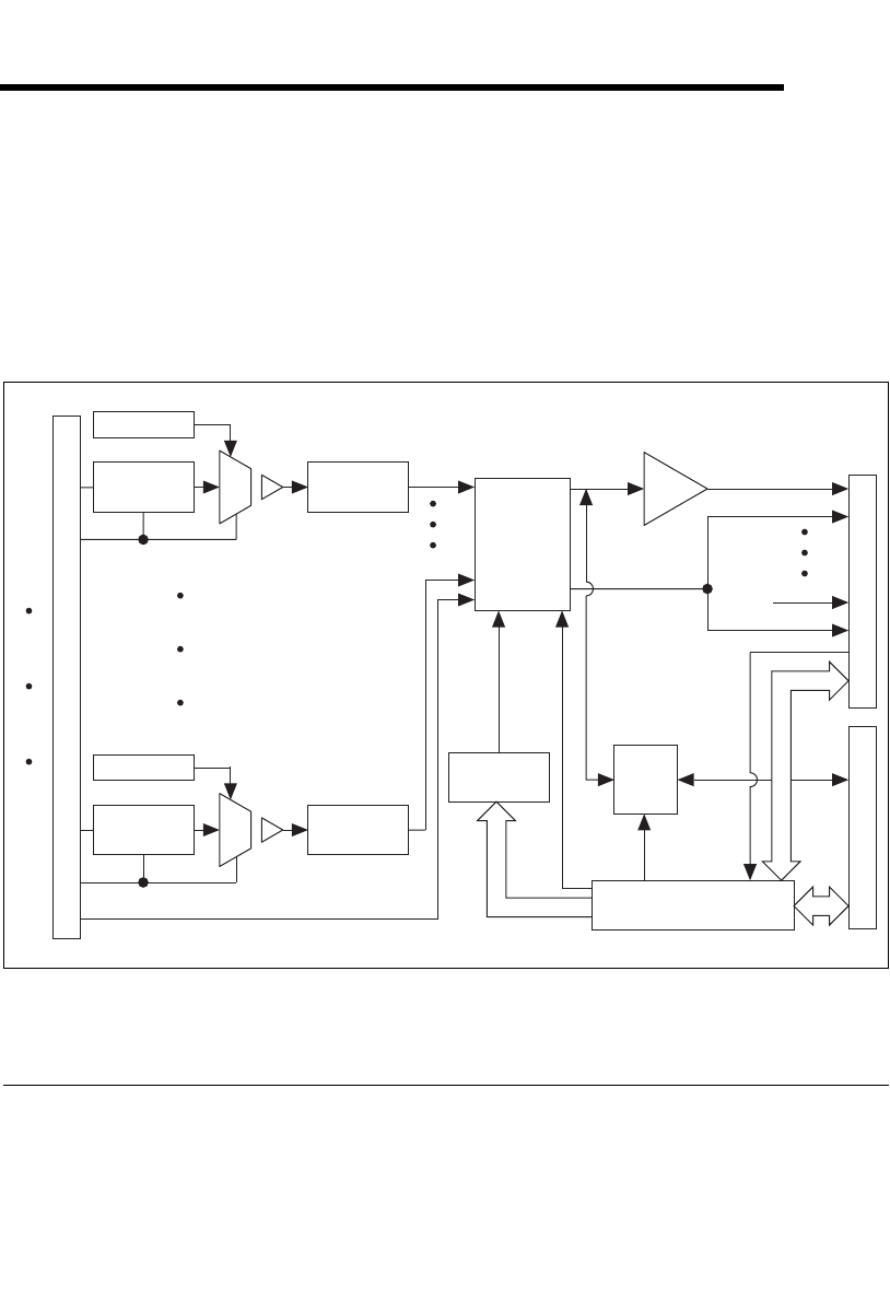
The section includes a brief overview and a detailed discussion of the
circuit features of the module. The two major modes of operation,
multiplexed and parallel mode, are discussed. Refer to Figure 4-1 while
reading this section.
Figure 4-1. SCXI-1125 Block Diagram
Gain
The SCXI-1125 has 12 different gain settings, from 1 to 2000, enabling
signal ranges ±5 V to ±2.5 mV. When the SCXI-1125 is used with a
terminal block that provides attenuation, the input range expands up to
1000 V. Refer to Appendix A, Specifications for a full list of input ranges.
Gain Select
Rear Signal Connector
AI 0+
AI 0–
AI 7+
AI 0
AI 7
AI 7–
AI 0
AI 7
+
Gain Select
+
+
–
+
–
MTEMP
Lowpass
Filter
Lowpass
Filter
Lowpass
Filter
Lowpass
Filter
Front Signal Connector
Analog
Multiplexer
Multiplexer
Control
Buffer
Analog
Bus
Switch
To
Analog
Bus
Scan
Clock
Digital Interface
and Control
SCXIbus Connector

Chapter 4 Theory of Operation
SCXI-1125 User Manual 4-2 ni.com
Refer to the Configurable Settings in MAX section of Chapter 3,
Configuring and Testing, for more information about programmatically
setting gain using range settings in MAX. For more information about
programmatically setting gain using range settings in NI-DAQmx and
Traditional NI-DAQ (Legacy), refer to the Developing Your Application in
NI-DAQmx section or the Developing Your Application in Traditional
NI-DAQ (Legacy) section, respectively, of Chapter 5, Using the
SCXI-1125.
Filter Bandwidth and Cutoff Frequency
The SCXI-1125 provides two filtering stages with an overall response of a
four-pole Butterworth filter. You can control the cutoff frequency of the
filter through software. You can choose 4 Hz or 10 kHz. For additional
flexibility in cutoff frequency settings and for greater suppression, NI
recommends combining the hardware filtering provided by the SCXI-1125
with digital filtering. NI recommends using the Advanced Analysis
functions of LabVIEW, LabWindows/CVI, or Measurement Studio. By
combining hardware anti-aliasing with digital filtering, you can choose any
cutoff frequency.
The Advanced Analysis functions are only available in LabVIEW Full or
Professional Development Systems, and LabWindows/CVI Base or Full
Development Systems.
Refer to the Configurable Settings in MAX section of Chapter 3,
Configuring and Testing, for more information about programmatically
setting the cutoff frequency of the filter in MAX. For more information
about programmatically setting the cutoff frequency of the filter in
NI-DAQmx and Traditional NI-DAQ (Legacy), refer to the Developing
Your Application in NI-DAQmx section or the Developing Your
Application in Traditional NI-DAQ (Legacy) section, respectively, of
Chapter 5, Using the SCXI-1125.
Operating in Multiplexed Mode
You can configure the SCXI-1125 to operate in multiplexed mode as
described in Chapter 1, About the SCXI-1125. Using this mode of
operation, you can scan all input channels of the SCXI-1125 into one
output channel that is read by the National Instruments DAQ device. You
can also multiplex the CJC channel that connects to a sensor on the SCXI
terminal block for making temperature measurements.

Chapter 4 Theory of Operation
© National Instruments Corporation 4-3 SCXI-1125 User Manual
Multiplexed Hardware Operation Theory
When you configure a module for multiplexed mode operation, the routing
of multiplexed signals to the E/M Series DAQ device depends on which
module in the SCXI system is cabled to the E/M Series DAQ device. There
are several possible scenarios for routing signals from the multiplexed
modules to the E/M Series DAQ device. If the module being scanned is not
directly cabled to the E/M Series DAQ device, the module sends its signals
through the SCXIbus to the cabled module. The cabled module, whose
routing is controlled by the SCXI chassis, routes the SCXIbus signals to the
E/M Series DAQ device through the CH0 signal on the rear signal
connector. If the E/M Series DAQ device scans the cabled module, the
module routes its input signals through the CH0 signal on the rear signal
connector. The power of SCXI multiplexed scanning is its ability to route
many input channels to a single channel on the E/M Series DAQ device.
Note The SCXI-1125 parallel outputs continuously drive the rear signal connector output
pins even when you configure the module in multiplexed mode. If the module is cabled to
an E/M Series DAQ device in multiplexed mode, the differential inputs 1 through 7 on the
E/M Series DAQ device cannot be used for general-purpose analog input. Refer to
Appendix D, Common Questions, for more information on available pins on the rear signal
connector.
Multiplexed mode is typically used for performing scanning operations
with the SCXI-1125. Immediately prior to a multiplexed scanning
operation, the SCXI chassis is programmed with a module scan list that
controls which module sends its output to the SCXIbus during a scan. You
can specify this list to scan the modules in the chassis in any order, with an
arbitrary number of channels for each module entry in the list. You can
randomly scan the channels on the SCXI-1125, meaning channels can be in
any order and occur multiple times in a single scan. When performing
multiple scans, the list pointer of the module automatically wraps around
and starts scanning with the first channel in the scan list.
Operating in Parallel Mode
You can configure the SCXI-1125 to operate in parallel mode as described
in Chapter 1, About the SCXI-1125. In parallel mode, all eight analog
output channels on the SCXI-1125 are connected to eight analog input
channels on the E/M Series DAQ device. The CJC channel is not
accessible. Every SCXI-1125 configured for parallel mode must have a
E/M Series DAQ device directly cabled to it.
Chapter 4 Theory of Operation
SCXI-1125 User Manual 4-4 ni.com
Theory of Parallel Hardware Operation
In parallel mode, the CH0 signal on the rear signal connector is configured
as the output of the SCXI-1125 analog input channel 0. The rear signal
connector carries each of the analog outputs of the SCXI-1125 to the
connected DAQ device. You can use an SCXI-1180 feedthrough connector
to make each of the outputs available at the front of the chassis; which is
useful for cascading these signals to other modules for additional signal
conditioning purposes. Parallel mode allows you to bypass scanning and
you are not limited by the settling time required by the multiplexer of
SCXI-1125. You can scan the channels more accurately at a faster rate,
depending on which E/M Series DAQ device you connect to the module.

© National Instruments Corporation 5-1 SCXI-1125 User Manual
5
Using the SCXI-1125
This chapter discusses typical applications for the SCXI-1125. While this
list is not comprehensive, it provides some guidance on how to improve
measurement accuracy for some of the most popular applications of the
SCXI-1125. Advanced operations such as calibration and using the CJC
channel are discussed as well.
Temperature Measurements Using Thermocouples
Making isolated temperature measurements from thermocouples is a
common use of the SCXI-1125. This section discusses how to use
thermocouples, CJC, and how to calculate the temperature accuracy of the
SCXI-1125.
NI recommends using the SCXI-1328 terminal block to make
thermocouple measurements with the SCXI-1125. Although you can use
many of the SCXI terminal blocks for thermocouple measurements, the
SCXI-1328 has an isothermal design that reduces temperature gradients
within the terminal block housing. This design reduces the CJC errors
which might reduce the accuracy of your temperature measurement. Most
SCXI terminal blocks available for the SCXI-1125 contain a cold-junction
temperature sensor, which is used for measuring ambient temperature. This
sensor connects to a special channel on the SCXI-1125 inside the terminal
block close to where the thermocouple connects to the screw terminals.
Note Place the SCXI chassis away from extreme temperature gradients to minimize the
temperature gradient inside the terminal block and maintain its isothermal nature for
accurate CJC.
A thermocouple relies on the principle that a small voltage that varies with
temperature is produced at the junction of two dissimilar metals. CJC is
necessary because the junction between the end of the thermocouple lead
wires and the screw terminals produces a small potential difference, adding
error to the thermocouple voltage. Knowing the temperature at the point
where the thermocouple is connected to the measurement instrument
allows you to determine the correct temperature reading at the
thermocouple junction. Due to the nonlinear relationship between
Chapter 5 Using the SCXI-1125
SCXI-1125 User Manual 5-2 ni.com
thermocouple junction voltage and temperature, this voltage conversion
(linearization) is best done through software.
NI-DAQ has built-in scaling for most thermocouple types. In NI-DAQmx,
you can create a thermocouple task or global channel. In Traditional
NI-DAQ (Legacy), you can create a thermocouple virtual channel.
If you choose to not let the driver scale the voltage readings for you in
software, you must do several conversions by using conversion coefficients
that reflect the voltage-temperature relationship for the type of
thermocouple and CJC being used. Complete the following steps to
accurately determine thermocouple temperature:
1. Read the voltage from the CJC sensor and convert this voltage to a
temperature.
2. Convert this temperature to the corresponding voltage for the
thermocouple type in use.
3. Read the input voltage from the thermocouple.
4. Add the two voltages.
5. Translate the resultant voltage into the thermocouple temperature
reading.
You have completed the steps to get the true temperature reading from the
thermocouple junction.
National Instruments software ADEs have useful conversion functions for
CJC. In LabVIEW, virtual channels with the CJC channel invoked or the
Convert Thermocouple Reading VI are used. In C, use the NI-DAQ
function, Thermocouple_Convert. In C, you might also need to use the
function Thermistor_Convert, if your terminal block uses a thermistor
to perform CJC. For more information about CJC, refer to your software
ADE user documentation.
To calculate the temperature accuracy of your SCXI-1125, you must
consider several factors. First, the type of sensor and the temperature range
you expect directly affects which gain your SCXI-1125 module uses for
voltage readings, thereby directly affecting the resolution with which you
can read temperature. After determining the range necessary for your
application, you can apply the measurement accuracy specifications of the
SCXI-1125; such as offset error, gain error, and noise to determine how
these will affect your temperature measurement. Next, you must consider
the accuracy of your cold-junction sensor and incorporate this into the total
temperature error of your reading. Finally, the accuracy of the DAQ device
you use must be factored in to determine your overall system error.
Chapter 5 Using the SCXI-1125
© National Instruments Corporation 5-3 SCXI-1125 User Manual
Complete the following steps to calculate the overall temperature error
using the SCXI-1125 with an E Series MIO DAQ device:
1. Based on the required temperature range and the type of sensor,
determine the gain to use. For example, using a K-type thermocouple
with a required temperature range of 0 to 100 °C, the corresponding
voltage range is –1.002 mV to 4.0962 mV (averaging 41.0 µV/°C in
this range). For this example, use a gain of 1000 for this temperature
range to get maximum temperature resolution.
2. Next, look up the analog accuracy specifications from Appendix A,
Specifications, for the gain and filter settings you have chosen. You
must consider how offset, gain, and system noise affect your
measurement. You might also consider common-mode rejection,
temperature drift, and other specifications based on the operating
environment. For example, using a gain of 1000, the offset error is
± 0.2 µV, the gain error is ± 0.03% which corresponds to ± 1.43 µV at
full-scale temperature, and the system noise is 100 Vrms (use peak
noise which is about 3 times this, or 300 nVpk) because of the 4 Hz
filter. In this example you might or might not be able to average out the
noise. The total error is ± 1.73 µV at the full-scale temperature range,
which gives a preliminary accuracy of ± 0.04 °C (1.73 µV divided by
41.0 µV/°C).
3. Next, consider the accuracy of the cold-junction sensor you are using.
For example, using the SCXI-1328, which, at about room temperature
with little temperature gradient, has an accuracy of ± 0.5 °C. You must
convert this temperature accuracy back to a voltage corresponding to a
K-type thermocouple accuracy at 25 °C. This conversion produces
about ± 20 µV of error.
4. Add the two voltages and determine the overall temperature error. For
example, the total error due to the SCXI portion of the system in this
example now becomes ± 21.73 µV. This total error corresponds to
about ± 0.53 °C (21.73 µV divided by 41.0 µV/°C) temperature error
using the K-type thermocouple at this range.
5. Determine the contribution of DAQ device error. For example, if using
a 12-bit DAQ device, the DAQ device contributes a gain of 2, and
therefore the code width becomes 2.44 µV. As a result, the total system
error now becomes ± (21.73 µV + 2.44 µV), which corresponds to
about 0.59 °C. If you were to choose a 16-bit board, you can achieve a
code width of 0.153 µV, producing a total system error of 0.53 °C.

Chapter 5 Using the SCXI-1125
SCXI-1125 User Manual 5-4 ni.com
Making High-Voltage Measurements
Another common use of the SCXI-1125 is to make measurements up to
1000 VDC. Making measurements beyond ± 5 V requires use of the an
attenuator terminal block. The SCXI-1327 and SCXI-1313A terminal
blocks have a selectable attenuator for choosing between no attenuation or
100:1 attenuation, which allows you to use the SCXI-1125 with up to
300 Vrms when using the SCXI-1327 and up to 150 Vrms when using the
SCXI-1313A.
The TBX-1316 has a fixed 200:1 attenuation, which allows you to use the
SCXI-1125 with up to 1000 VDC, Measurement Category I.
The SCXI-1327 and SCXI-1313A also include a cold-junction sensor so
you can combine thermocouple measurements with high-voltage
measurements. When making signal connections, or when working with
high-voltage signals, refer to the terminal block installation guide. If you
are using the SCXI-1125 to measure signals with attenuation on the
terminal block, an external bias resistor is not needed, because a bias
resistor is already used for achieving the attenuation.
Table 5-1 lists the extended ranges of gain possible with the SCXI-1327
and SCXI-1313A. Table 5-2 lists the extended gain possible with the
TBX-1316.
Table 5-1. Extended Gain and Range Using the SCXI-1327 or SCXI-1313A
Overall
Gain
Input
Range
SCXI-1125
Gain
SCXI-1327
Attenuation
SCXI-1313A
Attenuation
0.01 ± 300 V 1 100 —
0.02 ± 250 V 2 100 —
0.002 ± 150 V 2 100 100
0.05 ± 100 V 5 100 100
0.1 ± 50 V 10 100 100
0.2 ± 25 V 20 100 100
0.5 ± 10 V 50 100 100
2.5 ± 2 V 250 100 100
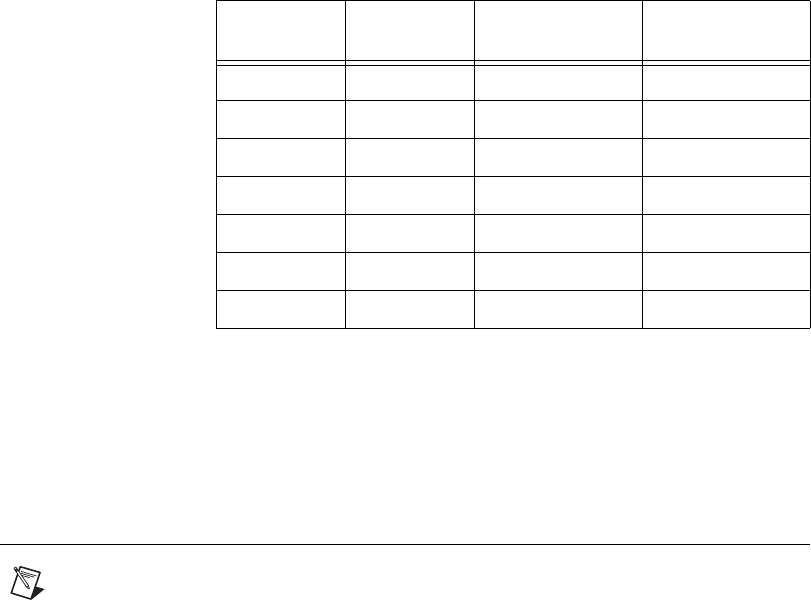
Chapter 5 Using the SCXI-1125
© National Instruments Corporation 5-5 SCXI-1125 User Manual
The overall input impedance is reduced when attenuating the input, but this
is acceptable in most applications. Refer to terminal block installation
guides for more information. Appendix A, Specifications, shows how the
analog input specifications are affected with the addition of the SCXI-1327
terminal block.
Developing Your Application in NI-DAQmx
Note If you are not using an NI ADE, using an NI ADE prior to version 7.0, or are using
an unlicensed copy of an NI ADE, NI License Manager displays additional dialog boxes
so you can create a task or global channel in unlicensed mode. These dialog boxes continue
to appear until you install version 7.0 or later of an NI ADE.
This section describes how to configure and use NI-DAQmx to control the
SCXI-1125 in LabVIEW, LabWindows/CVI, and Measurement Studio.
These ADEs provide greater flexibility and access to more settings than
MAX, but you can use ADEs in conjunction with MAX to quickly create a
customized application.
Typical Program Flowchart
Figure 5-1 shows a typical program flowchart for creating a task to
configure channels, take a measurement, analyze and present the data, stop
the measurement, and clear the task.
Table 5-2. Extended Gain and Range Using the TBX-1316
Overall
Gain
Input
Range
SCXI-1125
Gain
TBX-1316
Attenuation
0.005 ± 1000 V 1 200
0.01 ± 500 V 2 200
0.025 ± 200 V 5 200
0.05 ± 100 V 10 200
0.1 ± 50 V 20 200
0.25 ± 20 V 50 200
1.25 ± 4 V 250 200
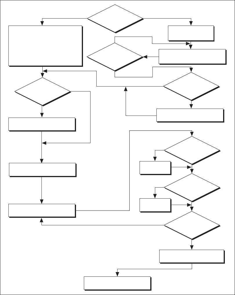
Chapter 5 Using the SCXI-1125
SCXI-1125 User Manual 5-6 ni.com
Figure 5-1. Typical Program Flowchart
Ye s
Create Channel
(Application Specific)
Adjust Timing Settings
Create a Task
Programmatically
Create Task in
DAQ Assistant
or MAX
No Hardware
Timing/Triggering?
Create Task Using
DAQ Assistant?
NoYes
No
Ye s
Configure Channels
Further Configure
Channels?
Start Measurement
Read Measurement
Clear Task
Continue Sampling?
Stop Measurement
Ye s
No
Analyze Data?
Display Data?
No
No
Process
Data
Graphical
Display Tools
Ye s
Ye s
Create Another
Channel?
No
Ye s
Chapter 5 Using the SCXI-1125
© National Instruments Corporation 5-7 SCXI-1125 User Manual
General Discussion of Typical Flowchart
The following sections discuss briefly considerations for a few of the steps
in Figure 5-1. These sections give an overview of some of the options and
features available when programming with NI-DAQmx.
Creating a Task Using DAQ Assistant or
Programmatically
When creating an application, first you must decide whether to create the
appropriate task using the DAQ Assistant or programmatically in the ADE.
Developing your application using DAQ Assistant gives you the ability to
configure most settings such as measurement type, selection of channels,
excitation voltage, signal input limits, task timing, and task triggering. You
can access the DAQ Assistant through MAX or your NI ADE. Choosing to
use the DAQ Assistant can simplify the development of your application.
NI recommends creating tasks using the DAQ Assistant for ease of use,
when using a sensor that requires complex scaling, or when many
properties differ between channels in the same task.
If you are using an ADE other than an NI ADE, or if you want to explicitly
create and configure a task for a certain type of acquisition, you can
programmatically create the task from your ADE using functions or VIs.
If you create a task using the DAQ Assistant, you can still further configure
the individual properties of the task programmatically with functions
or property nodes in your ADE. NI recommends creating a task
programmatically if you need explicit control of programmatically
adjustable properties of the DAQ system.
Programmatically adjusting properties for a task created in the DAQ
Assistant overrides the original, or default, settings only for that session.
The changes are not saved to the task configuration. The next time you load
the task, the task uses the settings originally configured in the DAQ
Assistant.
Adjusting Timing and Triggering
There are several timing properties that you can configure through the
DAQ Assistant or programmatically using function calls or property nodes.
If you create a task in the DAQ Assistant, you can still modify the timing
properties of the task programmatically in your application.
When programmatically adjusting timing settings, you can set the task to
acquire continuously, acquire a buffer of samples, or acquire one point at a

Chapter 5 Using the SCXI-1125
SCXI-1125 User Manual 5-8 ni.com
time. For continuous acquisition, you must use a while loop around the
acquisition components even if you configured the task for continuous
acquisition using MAX or the DAQ Assistant. For continuous and buffered
acquisitions, you can set the acquisition rate and the number of samples to
read in the DAQ Assistant or programmatically in your application. By
default, the clock settings are automatically set by an internal clock based
on the requested sample rate. You also can select advanced features such as
clock settings that specify an external clock source, internal routing of the
clock source, or select the active edge of the clock signal.
Configuring Channel Properties
All ADEs used to configure the SCXI-1125 access an underlying set of
NI-DAQmx properties. Table 5-3 shows some of these properties. You can
use Table 5-3 to determine what kind of properties you need to set to
configure the module for your application. For a complete list of
NI-DAQmx properties, refer to your ADE help file.
Note You cannot adjust some properties while a task is running. For these properties, you
must stop the task, make the adjustment, and re-start the application. Figure 5-1 assumes
all properties are configured before the task is started.
Note This is not a complete list of NI-DAQmx properties and does not include every
property you may need to configure your application. It is a representative sample of
important properties to configure for measurements. For a complete list of NI-DAQmx
properties and more information about NI-DAQmx properties, refer to your ADE help file.
Table 5-3. NI-DAQmx Properties
Property Short Name Description
Analog Input»General Properties»
Advanced»Range»High
AI.Max Specifies the upper limit of the
input range.
Analog Input»General Properties»
Advanced»Range»Low
AI.Min Specifies the lower limit of the
input range.
Analog Input»General Properties»
Filter»Analog Lowpass»Cutoff
Frequency
AI.Lowpass.CutoffFreq Specifies in hertz the
frequency corresponding to the
–3 dB cutoff of the filter. You
can specify 4.0 or 10000.

Chapter 5 Using the SCXI-1125
© National Instruments Corporation 5-9 SCXI-1125 User Manual
Acquiring, Analyzing, and Presenting
After configuring the task and channels, you can start the acquisition, read
measurements, analyze the data returned, and display it according to the
needs of your application. Typical methods of analysis include digital
filtering, averaging data, performing harmonic analysis, applying a custom
scale, or adjusting measurements mathematically.
NI provides powerful analysis toolsets for each NI ADE to help you
perform advanced analysis on the data without requiring you to have a
programming background. After you acquire the data and perform any
required analysis, it is useful to display the data in a graphical form or log
it to a file. NI ADEs provide easy-to-use tools for graphical display, such as
charts, graphs, slide controls, and gauge indicators. NI ADEs have tools
that allow you to easily save the data to files such as spread sheets for easy
viewing, ASCII files for universality, or binary files for smaller file sizes.
Completing the Application
After you have completed the measurement, analysis, and presentation of
the data, it is important to stop and clear the task. This releases any memory
used by the task and frees up the DAQ hardware for use in another task.
Note In LabVIEW, tasks are automatically cleared.
Developing an Application Using LabVIEW
This section describes in more detail the steps shown in the typical program
flowchart in Figure 5-1, such as how to create a task in LabVIEW and
configure the channels of the SCXI-1125. If you need more information or
for further instructions, select Help»VI, Function, & How-To Help from
the LabVIEW menu bar.
Note Except where otherwise stated, the VIs in Table 5-4 are located on the Functions»
All Functions»NI Measurements»DAQmx - Data Acquisition subpalette and
accompanying subpalettes in LabVIEW.

Chapter 5 Using the SCXI-1125
SCXI-1125 User Manual 5-10 ni.com
Table 5-4. Programming a Task in LabVIEW
Flowchart Step VI or Program Step
Create Task in DAQ Assistant Create a DAQmx Task Name Constant located on the
Controls»Modern»I/O»DAQmx Name Controls subpalette,
right-click it, and select New NI-DAQmxTask (MAX...).
Create a Task
Programmatically (optional)
DAQmx Create Task.vi—This VI is optional if you created
and configured your task using the DAQ Assistant. However, if
you use it in LabVIEW, any changes you make to the task will not
be saved to a task in MAX.
Create AI Channel (optional) DAQmx Create Virtual Channel.vi (AI Voltage by default,
to change to a channel, click AI Voltage and select the type of
analog input you want.—This VI is optional if you created and
configured your task and channels using the DAQ Assistant. Any
channels created with this VI are not saved in the DAQ Assistant.
They are only available for the present session of the task in
LabVIEW.
Adjust Timing Settings
(optional)
DAQmx Timing.vi (Sample Clock by default)—This VI is
optional if you created and configured your task using the DAQ
Assistant. Any timing settings modified with this VI are not
saved in the DAQ Assistant. They are only available for the
present session.
Configure Channels (optional) DAQmx Channel Property Node, refer to the Using a DAQmx
Channel Property Node in LabVIEW section for more
information. This step is optional if you created and fully
configured the channels using the DAQ Assistant. Any channel
modifications made with a channel property node are not saved
in the task in the DAQ Assistant. They are only available for the
present session.
Start Measurement DAQmx Start Task.vi
Read Measurement DAQmx Read.vi
Analyze Data Some examples of data analysis include filtering, scaling,
harmonic analysis, or level checking. Some data analysis tools
are located on the Functions»Signal Analysis subpalette and on
the Functions»All Functions»Analyze subpalette.

Chapter 5 Using the SCXI-1125
© National Instruments Corporation 5-11 SCXI-1125 User Manual
Using a DAQmx Channel Property Node in LabVIEW
You can use property nodes in LabVIEW to manually configure the
channels. To create a LabVIEW property node, complete the following
steps:
1. Launch LabVIEW.
2. Create the property node in a new VI or in an existing VI.
3. Open the block diagram view.
4. From the Functions toolbox, select Measurement I/O»
DAQmx - Data Acquisition, and select DAQmx Channel Property
Node.
5. Use the ActiveChans box to specify exactly what channel(s) you want
to configure. If you want to configure several channels with different
properties, separate the lists of properties with another ActiveChans
box and assign the appropriate channel to each list of properties.
Note If you do not use Active Channels, the properties are set on all of the channels in
the task.
6. Right-click ActiveChans, and select Add Element. Left-click the new
ActiveChans box. Navigate through the menus, and select the
property you wish to define.
Display Data You can use graphical tools such as charts, gauges, and graphs
to display your data. Some display tools are located on the
Controls»All Controls»Numeric»Numeric Indicators
subpalette and Controls»All Controls»Graph subpalette.
Continue Sampling For continuous sampling, use a While Loop. If you are using
hardware timing, you also need to set the DAQmx Timing.vi
sample mode to Continuous Samples. To do this, right-click the
terminal of the DAQmx Timing.vi labeled sample mode and
click Create»Constant. Click the box that appears and select
Continuous Samples.
Stop Measurement DAQmx Stop Task.vi (This VI is optional, clearing the task
automatically stops the task.)
Clear Task DAQmx Clear Task.vi
Table 5-4. Programming a Task in LabVIEW (Continued)
Flowchart Step VI or Program Step
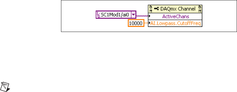
Chapter 5 Using the SCXI-1125
SCXI-1125 User Manual 5-12 ni.com
7. Change the property to read or write to either get the property or write
a new value. Right-click the property, go to Change To, and select
Write, Read, or Default Value.
8. After you have added the property to the property node, right-click the
terminal to change the attributes of the property, add a control,
constant, or indicator.
Figure 5-2. LabVIEW Channel Property Node with Lowpass Frequency Set at 10 kHz
on Channel SC1Mod1/ai0
9. To add another property to the property node, right-click an existing
property and left-click Add Element. To change the new property,
left-click it and select the property you wish to define.
Note Refer to the LabVIEW Help for information about property nodes and specific
NI-DAQmx properties.
Specifying Channel Strings in NI-DAQmx
Use the channel input of DAQmx Create Channel to specify the
SCXI-1125 channels. The input control/constant has a pull-down menu
showing all available external channels. The strings take one of the
following forms:
• single device identifier/channel number—for example SC1Mod1/ch0
• multiple, noncontinuous channels—for example SC1Mod1/ch0,
SC1Mod1/ch4
• multiple continuous channels—for example SC1Mod1/ch0:4
(channels 0 through 4)
• cold junction channel—SC1Mod1/_cjtemp
When you have a task containing SCXI-1125 channels, you can set the
properties of the channels programmatically using the DAQmx Channel
Property Node.

Chapter 5 Using the SCXI-1125
© National Instruments Corporation 5-13 SCXI-1125 User Manual
Follow the general programming flowchart or open an example to build a
basic virtual channel. You can use property nodes in LabVIEW to control,
configure, and customize the NI-DAQmx task and SCXI-1125. To create a
LabVIEW property node, complete the following steps:
1. Launch LabVIEW.
2. Create the property node in a new Virtual Instrument (VI) or in an
existing VI.
3. Open the block diagram view.
4. From the Functions tool bar, select NI Measurements,
DAQmx - Data Acquisition, and select the type of property node you
wish to configure.
5. Use the ActiveChans box to specify what channel(s) you want to
configure. If you want to configure several channels with different
properties, separate the lists of properties with another ActiveChans
box, and assign the appropriate channel to each list of properties.
6. Right-click ActiveChan and select Add Element. Left-click the new
ActiveChan box. Navigate through the menus and select the property
you wish to define.
7. You must change the property to read or write to either get the property
or write a new value. Right-click the property, go to Change To, and
select Write, Read, or Default Value.
8. After you have added the property to the property node, right-click
the terminal to change the attributes of the property, add a control,
constant, or indicator.
9. To add another property to the property node, right-click an existing
property and left-click Add Element. To change the new property,
left-click it and select the property you wish to define.
Note Refer to the LabVIEW Help for information about property nodes and specific
NI-DAQmx properties.

Chapter 5 Using the SCXI-1125
SCXI-1125 User Manual 5-14 ni.com
Text Based ADEs
You can use text based ADEs such as LabWindows/CVI, Measurement
Studio, Visual Basic, .NET, and C# to create code for using the
SCXI-1125.
LabWindows/CVI
LabWindows/CVI works with the DAQ Assistant in MAX to generate
code for a task. You can then use the appropriate function call to modify
the task. To create a configurable channel or task in LabWindows/CVI,
complete the following steps:
1. Launch LabWindows/CVI.
2. Open a new or existing project.
3. From the menu bar, select Tools»Create/Edit DAQmx Tasks.
4. Choose Create New Task In MAX or Create New Task In Project
to load the DAQ Assistant.
5. Configure the NI-DAQmx task following the instructions in the
Creating a Voltage Global Channel or Task section.
6. The DAQ Assistant creates the code for the task based on the
parameters you define in MAX and the device defaults. To change
a property of the channel programmatically, use the
DAQmxSetChanAttribute function.
Note Refer to the NI LabWindows/CVI Help for more information on creating NI-DAQmx
tasks in LabWindows/CVI and NI-DAQmx property information.
Measurement Studio (Visual Basic, .NET, and C#)
When creating a task in Visual Basic .NET and C#, follow the general
programming flow in Figure 5-1. You can then use the appropriate function
calls to modify the task. This example creates a new task and configures an
NI-DAQmx channel on the SCXI-112511251125. You can use the same
functions for Visual Basic .NET and C#.
Programmable NI-DAQmx Properties
All of the different ADEs that configure the SCXI-1125 access an
underlying set of NI-DAQmx properties. Table 5-5 provides a list of some
of the properties that configure the SCXI-1125. You can use this list to
determine what kind of properties you need to set to configure the device
for your application. For a complete list of NI-DAQmx properties, refer to
your ADE help file.

Chapter 5 Using the SCXI-1125
© National Instruments Corporation 5-15 SCXI-1125 User Manual
Note This is not a complete list of NI-DAQmx properties and does not include every
property you may need to configure your application. For a complete list of NI-DAQmx
properties and more information on NI-DAQmx properties, refer to your ADE help file.
Developing Your Application in Traditional NI-DAQ
(Legacy)
Note If you are not using an NI ADE, using an NI ADE prior to version 7.0, or are using
an unlicensed copy of an NI ADE, additional dialog boxes from the NI License Manager
appear allowing you to create a task or global channel in unlicensed mode. These messages
continue to appear until you install version 7.0 or later of an NI ADE.
This section describes how to configure and use Traditional NI-DAQ
(Legacy) to control the SCXI-1125 in LabVIEW, LabWindows/CVI,
Measurement Studio, and other text-based ADEs. These NI ADEs provide
greater flexibility and access to more settings than MAX, but you can use
ADEs in conjunction with MAX to quickly create a customized
application.
Table 5-5. NI-DAQmx Properties
Property Short Name Description
Analog Input»General Properties»
Advanced»Range»High
AI.Max Specifies the upper limit of the
input range.
Analog Input»General Properties»
Advanced»Range»Low
AI.Min Specifies the lower limit of the
input range.
Analog Input»General Properties»
Advanced»Gain and Offset»
Gain Value
AI.Gain Specifies a gain factor to apply to
the signal conditioning portion
of the channel.
Analog Input»Measurement Type AI.MeasType Indicates the measurement to take
with the analog input channel.

Chapter 5 Using the SCXI-1125
SCXI-1125 User Manual 5-16 ni.com
Traditional NI-DAQ (Legacy) in LabVIEW
LabVIEW is a graphical programming environment for test and
measurement application development with built-in easy to use tools for
data acquisition, analysis, and display. You can use functional graphical
blocks called subVIs to easily create a custom application that fully utilizes
the SCXI-1125 programmable functionality. Traditional NI-DAQ
(Legacy) provides several standard data acquisition subVIs as well as
subVIs specifically for use with the SCXI-1125.
For applications using Traditional NI-DAQ (Legacy) in LabVIEW, there
are two typical methods of addressing SCXI-1125 channels—virtual
channels (specifically virtual channels) and SCXI channel strings.
Depending on the needs of your application, you choose one of these
channel addressing methods to use in your LabVIEW application.
When you use virtual channels, the maximum number of channels per
E Series DAQ device is 512 in multichassis systems. NI recommends using
the virtual channel for ease of use. Refer to Appendix B, Using SCXI
Channel Strings with Traditional NI-DAQ (Legacy) 7.0 or Later, for more
information on how to create a virtual channel.
The SCXI channel string allows you to combine large numbers of channels
into fewer scan list entries, to measure the signal voltage level directly for
custom scaling, and to dynamically perform an offset null compensation in
your application. NI recommends using SCXI channel strings for more
advanced applications. In LabVIEW, an array of these channel strings
configures multiple modules for scanning. When using SCXI channel
strings, you can scan up to 3,072 channels in a multichassis system using a
single E Series DAQ device.
Note You cannot mix virtual channels with the SCXI channel strings within the same
channel string array.
To use virtual channels, enter the name of a virtual channel into the analog
input channel string. If using multiple virtual channels, enter them in a
different index in the channel string array, or separate them using a comma.
Since you can randomly scan analog input virtual channels, you can enter
the virtual channels you want to scan in any order or repeatedly in a channel
string array.
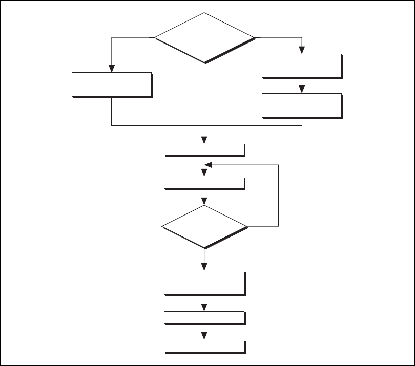
Chapter 5 Using the SCXI-1125
© National Instruments Corporation 5-17 SCXI-1125 User Manual
Typical Program Flow
After you have determined how you want to address the channels and
whether you want to configure the SCXI-1125 in MAX or LabVIEW, you
can design your application using a typical program flow such as the one
shown in Figure 5-3.
Figure 5-3. Typical SCXI-1125 Program Flow with Traditional NI-DAQ (Legacy)
Virtual Channel
Create Virtual
Channel in MAX
Use
Virtual Channel
or SCXI Channel
String
SCXI Channel String
Configure
Acquisition Settings
Configure
Mode Properties
Ye s
No
Start Acquisition
Take Measurements
Continue
Sampling?
Scale, Analyze,
and Display
Clear Acquisition
Error Handling

Chapter 5 Using the SCXI-1125
SCXI-1125 User Manual 5-18 ni.com
Configure the SCXI-1125 Settings Using Traditional NI-DAQ (Legacy) in
LabVIEW
You can configure SCXI-1125 settings in MAX using the virtual channel.
To configure and control the SCXI-1125 from LabVIEW, use the
AI Parameter VI. You can find AI Parameter VI in the function subpalette
Data Acquisition»Analog Input»Advanced Analog Input.
A parameter changed by the AI Parameter VI takes effect in hardware when
AI Start VI is called, not when AI Parameter VI is called. The AI parameter
VI merely changes the configuration in the driver memory. When called,
the AI Start VI reads the configuration settings in the driver memory and
then sends the actual control information to the SCXI-1125 module. A
setting established through AI Parameter VI is only valid for the LabVIEW
session and does not change the setting in MAX.
You can use the AI Parameter VI to configure the SCXI-1125 settings
shown in Table 5-6.
Table 5-6. Settings for Configuring the SCXI-1125 Through the AI Parameter
Software-
Configurable
Setting
AI Parameter VI
Allowable Settings
(Float In, Boolean In, or Value In)
Parameter
Name Valu e Data Type Values
Filter
Bandwidth
Filter Setting 14 Float In (dbl) 4.0, 10000.0
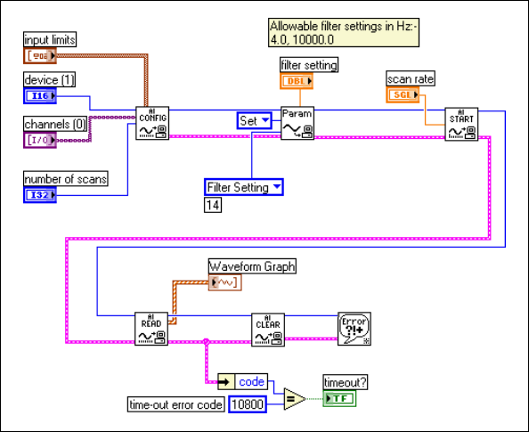
Chapter 5 Using the SCXI-1125
© National Instruments Corporation 5-19 SCXI-1125 User Manual
An example of using the AI Parameter VI to control an SCXI-1125 is
shown in Figure 5-4.
Figure 5-4. Using the AI Parameter VI to Set Up the SCXI-1125
Configure, Start Acquisition, and Take Readings Using Traditional
NI-DAQ (Legacy) in LabVIEW
After you have performed an offset null compensation and configured the
SCXI-1125 settings for your application, you can use the intermediate
analog input functions AI Config VI, AI Start VI, AI Read VI, and AI Clear
VI to create your data acquisition application. You can find the
intermediate data acquisition Traditional NI-DAQ (Legacy) functions in
the function subpalettes Data Acquisition»Analog Input. NI recommends
using the intermediate analog input functions for most SCXI-1125
applications. For more information about using the intermediate data
acquisition Traditional NI-DAQ (Legacy) functions, refer to the LabVIEW
Measurements Manual. You also can use the LabVIEW Help for more
detailed information about the various inputs and outputs of these
functions.
Chapter 5 Using the SCXI-1125
SCXI-1125 User Manual 5-20 ni.com
Convert Scaling Using Traditional NI-DAQ (Legacy) in LabVIEW
If you need scaling, you can either use an analog input voltage virtual
channel with a custom scale configured in MAX or SCXI channel strings,
and provide scaling in your LabVIEW application.
If you are using SCXI channel strings, you can easily convert the
SCXI-1125 voltage signal measurements in your application into scaled
units of interest such as pounds or newtons. LabVIEW has some common
conversion scaling functions such as the Scaling Constant Tuner VI in the
function subpalette Data Acquisition»Signal Conditioning.
You also can use an Expression Node or Formula Node to convert voltage
signal measurements into whatever units your application requires. You can
find an Expression Node in the function subpalette Numeric. You can find
Formula Nodes in the Function subpalettes Analyze»Mathematics»
Formula. For more information about using the Expression Node or
Formula Node, refer to the LabVIEW User Manual. You also can use the
LabVIEW Help for more detailed information about how to use these nodes
to perform mathematical calculations such as scaling conversions.
Analyze and Display Using Traditional NI-DAQ (Legacy) in LabVIEW
In LabVIEW, you can easily analyze SCXI-1125 measurements with a
variety of powerful analysis functions that you can find in the function
subpalettes Analyze»Waveform Conditioning and Analyze»Signal
Processing. You can perform post acquisition processing such as
waveform comparisons, harmonic analysis, and digital filtering. For more
information about these VIs, refer to the LabVIEW Analysis Concepts
manual. You also can use the LabVIEW Help for more detailed information
about how to use the analysis VIs.
In LabVIEW, you also can easily display SCXI-1125 measurements with a
variety of graphical waveform graphs, numeric slides, gauges, and other
indicators. You can find useful graphical controls and indicators for user
interaction with your application in the controls subpalettes. For more
information about these VIs, refer to the LabVIEW User Manual. You also
can use the LabVIEW Help for more detailed information about how to use
graphical controls and indicators in your application.
Chapter 5 Using the SCXI-1125
© National Instruments Corporation 5-21 SCXI-1125 User Manual
Traditional NI-DAQ (Legacy) in Text-Based ADEs
NI text-based ADEs, such as LabWindows/CVI, Measurement Studio
for Microsoft Visual Basic, and Measurement Studio for Microsoft
Visual C++, offer help in the development of test and measurement
applications. These ADEs provide easy data acquisition, data analysis,
graphical display, and data logging tools. Refer to the ADE user manual for
more information about how to use these features.
The high-level data acquisition tools provided in LabWindows/CVI and
Measurement Studio allow you to easily use virtual channels configured in
MAX providing easy configuration and programming of the data
acquisition systems. However, some of the more advanced features of the
SCXI-1125 are not accessible through this easy-to-use API. For more
advanced features or for more explicit control of the programmatic
attributes, use the low-level DAQ functions provided in the Traditional
NI-DAQ (Legacy) C API. Refer to the ADE user documentation for more
information about how to use the high-level data acquisition tools that are
provided in your NI ADE.
For more advanced SCXI-1125 applications, or if you are using an ADE
other than an NI ADE, you can use the Traditional NI-DAQ (Legacy) C API
to call functions from the DAQ driver dynamically linked library (dll).
Configuring System Settings Using Traditional NI-DAQ (Legacy) C API
Start the configuration of the acquisition by ensuring that the SCXI-1125
module and SCXI chassis are in their default states, and that the driver
software configuration matches the states the actual physical hardware
configuration. After setting the hardware and software to the defaults of the
module(s), you can configure any module settings that vary from the
default configuration settings. You also should configure the acquisition
parameters using the functions in Table 5-7. For additional information
such as the function prototypes, parameters, and usage instructions for each
function, refer to the Traditional NI-DAQ (Legacy) Function Reference
Help installed by default in Start»Programs»National Instruments»
NI-DAQ.

Chapter 5 Using the SCXI-1125
SCXI-1125 User Manual 5-22 ni.com
Note NI strongly recommends monitoring the built-in error status of each NI-DAQ
function. The NI-DAQ C API provides the NIDAQErrorHandler function, which ensures
that a specified NI-DAQ function executed properly, and assists in handling error messages
and reporting.
Configure Module Settings Using Traditional NI-DAQ (Legacy) C API
After configuring the hardware for acquisition, you must load the various
channel attributes such as filter, gain, and excitation appropriate for your
application explicitly using the NI-DAQ function calls shown in Table 5-8.
For more information regarding each setting, refer to the Traditional
NI-DAQ (Legacy) Function Reference Help installed by default in
Start»Programs»National Instruments»NI-DAQ.
Table 5-7. Configuration Functions
Function Description
SCXI_Reset Resets the hardware such as the specified module to its default state.
You also can use SCXI_Reset to reset the SCXI chassis Slot 0 scanning
circuitry or reset the entire chassis.
The SCXI-1125 default conditions are:
• Gain set at 1000.0
• 4 Hz lowpass filter
SCXI_Load_Config Loads the SCXI chassis configuration information you established in
MAX. Sets the software states of the chassis and the modules present to
their default states. This function makes no changes to the hardware
state of the SCXI chassis or modules. It is possible to programmatically
change the configuration you established in MAX using the
SCXI_Set_Config function.
SCXI_SCAN_Setup Initializes multiplexing circuitry for a scanned data acquisition
operation. Initialization includes storing a table of the channel sequence
and gain setting for each channel to be digitized (MIO and AI devices
only). You cannot repeat channels or use nonsequential channels when
using the SCXI_SCAN_Setup function.
SCXI_MuxCtr_Setup Programs the E Series DAQ device with the correct number of channels
multiplexed per scan. This number must match the total number of
channels programmed in SCXI_SCAN_Setup.

Chapter 5 Using the SCXI-1125
© National Instruments Corporation 5-23 SCXI-1125 User Manual
Perform Offset Null Compensation Using Traditional NI-DAQ (Legacy)
C API
After configuring the system settings and module properties, you
can perform an offset null compensation programmatically using
SCXI_Calibrate. SCXI_Calibrate takes measurements and adjusts the
coarse and fine offset null potentiometers to minimize or eliminate any
electrical offset for a channel. Repeat this process for each channel by
calling the SCXI_Calibrate function in a loop. Use the resulting
imbalance in your application as a software correction factor by
determining the residual voltage from the imbalance, and subtracting this
residual offset from each future measurement. For more information
regarding the operation of SCXI_Calibrate, refer to the Traditional
NI-DAQ (Legacy) Function Reference Help installed by default in Start»
Programs»National Instruments»NI-DAQ.
Perform Acquisition Using Traditional NI-DAQ (Legacy) C API
There are several NI-DAQ functions you can use to take measurements.
Usually in SCXI the preference is to take multiple samples from multiple
channels using the SCAN_Op function. SCAN_Op performs a synchronous,
multiple-channel scanned data acquisition operation. SCAN_Op does not
return until Traditional NI-DAQ (Legacy) acquires all the data or an
acquisition error occurs (MIO, AI, and DSA devices only). For this reason,
it is sometimes useful to use SCAN_Op in conjunction with the function
Timeout_Config, which establishes a timeout limit synchronous
functions to ensure that these functions eventually return control to your
application. After acquiring data using SCAN_Op, the resultant data is not
organized by channel, so you should demultiplex the data using
SCAN_Demux. SCAN_Demux rearranges, or demultiplexes, data acquired by
a SCAN_Op into row-major order, meaning each row of the array holding
Table 5-8. NI-DAQ Functions Used to Configure SCXI-1125
Channel
Setting NI-DAQ Function to Use
Significant
Parameters
Possible Parameters
Values
Gain SCXI_Set_Gain f64 gain
(gain setting)
1, 2, 5, 10, 20, 50, 100,
200, 250, 500, 1000,
2000
Bandwidth SCXI_Configure_Filter f64 freq
(filter cutoff
frequency if
filterMode = 1)
4.0, 10,000.0 Hz
Chapter 5 Using the SCXI-1125
SCXI-1125 User Manual 5-24 ni.com
the data corresponds to a scanned channel for easier access by
C applications. BASIC applications need not call SCAN_Demux to
rearrange two-dimensional arrays since these arrays are accessed in
column-major order. For more information regarding each acquisition
function, refer to the Traditional NI-DAQ (Legacy) Function Reference
Help installed by default in Start»Programs»National Instruments»
NI-DAQ.
Perform Scaling, Analysis, and Display
After acquiring raw voltage data from the acquisition functions, most
applications require adjustment by device calibration constants for
accuracy, scaling measured voltage, analysis, and graphical display.
The SCXI-1125 has stored software calibration constants loaded on the
module EEPROM that are used to achieve the absolute accuracy
specifications. SCXI_Scale scales an array of binary data acquired from
an SCXI channel to voltage using the stored software calibration constants
when it scales the data. You must call SCAN_Demux before SCXI_Scale if
you have multiple channels in the scan. For more information regarding
SCXI_Scale, refer to the Traditional NI-DAQ (Legacy) Function
Reference Help installed by default in Start»Programs»National
Instruments»NI-DAQ.
After you have adjusted the measurement by the appropriate calibration
constants using SCXI_Scale, you can use a function from the NI
conversion library convert.h to convert a voltage or voltage buffer from
a voltage to units of temperature or strain. NI-ADEs also provide many
powerful analysis functions to perform digital filtering, harmonic analysis,
averaging, and complex mathematics on measurements.
After performing scaling and analysis on the acquired data, you can display
the measurements in several ways. You can use any built in GUI tools in
your ADE. NI ADEs provide many graphical controls and indicators such
as charts, graphs, gauges, slides, and plots that you can use to display
the data. There is also a built in function, found in nidaqex.h, called
NIDAQPlotWaveform that you can use to generate a simple plot of the
data.
Using Software for Multiplexed Scanning
Performing scanning operations in software depends on the ADE you are
using. While using LabVIEW, or Visual Basic, all scanning operations are
prepared in software by using an SCXI channel string as the input to the
channel parameter in the analog input VI or function. These ADEs also

Chapter 5 Using the SCXI-1125
© National Instruments Corporation 5-25 SCXI-1125 User Manual
support virtual channels using Data Neighborhood (DAQ Channel Wizard)
in MAX. In LabWindows/CVI, C, or C++ development environments,
several NI-DAQ function calls need to be made to set up each module
involved in the scan, the chassis, and the E Series DAQ device controlling
the scan. In Measurement Studio, SCXI channels must be configured as
virtual channels (tags) in MAX.
A discussion describing how to implement multiplexed scanning in the
different ADEs follows. Refer to your ADE manual and the DAQ analog
input examples that come with your application software for more detailed
information on programming the SCXI modules for scanning in
multiplexed mode.
LabVIEW and the SCXI Channel String
For LabVIEW, and Visual Basic, the channel string determines the
sequence in which SCXI channels are scanned. In LabVIEW, an array of
these channel strings configures multiple modules in the scan list. When the
application program runs, the channel string is used for programming the
channel information into the SCXI system. The format of the channel string
is as follows:
obx ! scy ! mdz ! channels
where
•obx is the onboard E Series DAQ device channel, with x representing
a particular channel where the multiplexed channels are sent. This
value is 0 for DAQ channel 0 in a single-chassis system. In a
multichassis or remote chassis system, however, the E Series DAQ
device channel x corresponds to chassis number n–1, where DAQ
device channel x is used for scanning the nth chassis in the system.
•scy is the SCXI chassis ID, where y is the number you chose when
configuring your chassis.
•mdz is the slot position where the module is located, with z being the
particular slot number. The slots in a chassis are numbered from left to
right, starting with 1.
Note The
ob
x
!
specifier is optional and causes the gains on the module and E Series
DAQ device to be automatically set to fit the input limits parameter. When this specifier is
omitted, the default gain on the E Series DAQ device, usually the lowest gain, is used, but
the SCXI-1125 gain is adjusted to fit the input limits.

Chapter 5 Using the SCXI-1125
SCXI-1125 User Manual 5-26 ni.com
The last parameter, channels, is the list of channels that are scanned for
module z. It can have several formats:
•ob
x
! sc
y
! md
z
! n, where n is a single input channel.
•ob
x
! sc
y
! md
z
! n1:n2, where n1 and n2 represent a sequential
list of input channels, inclusive.
•ob
x
! sc
y
! md
z
! cjtemp, where cjtemp is the CJC channel.
You can scan this channel with other analog input channels. For
compatibility reasons, you can use mtemp in place of cjtemp.
•ob
x
! sc
y
! md
z
! (n1, n2, n3:n4, n1, n5, n2), where n1, n2, and
n5 represent single channels, not necessarily sequential, and n3 and n4
represent the endpoints of a sequential list of channels, inclusive. In
this case, channels n1 and n2 have explicitly been repeated in the
channel list. This random scanning format is not supported on all SCXI
modules.
•ob
x
! scy ! mdz ! calgnd n1:n2 where n1 and n2 represent a list of
autozeroed channels, inclusive. In this case autozero channels cannot
be scanned with input channels or the cold-junction channel, but must
be scanned separately. This feature is useful for measuring offsets that
appear due to temperature drifts in the analog circuitry. You can
subtract these offsets from subsequent input readings to correct for
temperature drift. Refer to Appendix A, Specifications, for
determining how temperature drift can affect your measurement
accuracy.
Note Repeating channels or having channels out of sequence in a scan list is not supported
on all SCXI modules. Please refer to the manual of each module for information on this
feature.
LabVIEW and the Virtual Channel String
For LabVIEW, Measurement Studio, and Visual Basic, the channel string
can also contain virtual channels. For the SCXI-1125, these virtual
channels are analog input channels you create that have custom names
(called tags in Measurement Studio), that perform scaling, linearization,
autozeroing, and CJC transparently without additional code. Virtual
channels are useful when sensors requiring different scaling factors are
used on the same SCXI-1125 channel. Using virtual channels, sensors
needing special scaling can be used in a generic analog input application
without performing hard-coded scaling or linearization. If the scaling
changes or you want to connect a different sensor to the SCXI-1125, no
changes are needed in the application. All that is required is creating a
different virtual channel and using its name in the channel string.

Chapter 5 Using the SCXI-1125
© National Instruments Corporation 5-27 SCXI-1125 User Manual
Note You cannot mix virtual channels with the SCXI channel strings shown in the
previous section.
To create a virtual channel for the SCXI-1125, insert a new analog input
channel in the Data Neighborhood path in MAX, name it, and then follow
the software prompts to create virtual temperature channels, voltage
channels, or customized analog input channels. For more information on
virtual channels, consult the MAX online help file.
To use the virtual channels, enter the name of the virtual channel into the
analog input channel string. If using multiple virtual channels, separate
them using a comma or enter them in a different index in the channel string
array. The application does all scaling, linearization, autozeroing, and CJC
automatically.
Note Virtual analog input channels can be randomly scanned; therefore, virtual channels
can be entered in any order or repeated in the channel string.
Performing a Multiplexed Scan
To perform a multiplexed scan in your application, perform the following
steps:
1. Open an analog input example in your ADE.
2. Enter the appropriate SCXI channel string or virtual channel string into
the channels parameter.
3. Either enter the input limits for signals connected to the module to
adjust the gain settings in your system, or use the default gain settings
from the configuration utility, and then run the application. When
using virtual channels, the default input limits configured in the virtual
channel configurator are used.
You have completed a multiplexed scan using your SCXI-1125.
This is not a comprehensive discussion of SCXI scanning using LabVIEW
or Measurement Studio, but it should give you enough information to help
you get started with the examples that are shipped with these software
packages.
Chapter 5 Using the SCXI-1125
SCXI-1125 User Manual 5-28 ni.com
C and Low-Level DAQ Functions
When using a C-based environment, several steps are needed to configure
the SCXI-1125 for multiplexed scanning. The following procedure outlines
the steps for programming with the low-level DAQ function calls:
1. Prepare the SCXI-1125 settings by either loading the original SCXI
configuration settings using SCXI_Load_Config, or by specifying
the gain and filter settings using SCXI_Set_Gain and
SCXI_Configure_Filter.
2. Use SCXI_SCAN_Setup to specify the module scan list, the start
channel of each module, and the number of channels to scan on each
module. SCXI_SCAN_Setup accepts an array of start channels and an
array of the number of channels to scan in each module. It is not
possible to repeat channels or use nonsequential channels using
SCXI_SCAN_Setup.
3. Next, use SCXI_MuxCtr_Setup to program the E Series DAQ device
with the correct number of channels multiplexed per scan. This
number must match the total number of channels programmed in
step 2.
You are now ready to acquire the channel data with the E Series DAQ
device. If you are using a multifunction E Series DAQ device, you can use
SCAN_OP to perform the scanning operation. After scanning, convert the
binary data to voltage data using SCXI_Scale. Refer to the NI-DAQ User
Manual for additional information on scanning with DAQ devices.
Using Software for Parallel Scanning
Performing scanning operations in parallel mode requires no special
channel strings or function calls for setting up channel sequencing as is
required in multiplexed mode. Scanning the SCXI-1125 channels on a
differentially configured DAQ device is done as if there were no
SCXI-1125 module connected. The only requirement is that you must
configure the module for parallel mode in MAX as described in Chapter 1,
About the SCXI-1125.
LabVIEW and Parallel Mode
In LabVIEW, the SCXI-1125 configuration settings are automatically
passed from MAX. LabVIEW can also set the SCXI-1125 configuration
parameter, operating mode, to parallel or multiplexed programmatically
by using the Set SCXI Information VI. In Measurement Studio, set the
operating mode using MAX as described in Chapter 1, About the
SCXI-1125.

Chapter 5 Using the SCXI-1125
© National Instruments Corporation 5-29 SCXI-1125 User Manual
After parallel mode has been configured in software, you can scan the
SCXI-1125 channels by entering the corresponding E Series DAQ device
channels or a sequential SCXI channel string in the channel parameter in
the analog input application. You can also enter virtual channels; however,
in parallel mode, virtual channels containing CJC are disabled in MAX.
C and Parallel Mode
When using a C-based ADE, you need no special steps for configuring the
chassis, the SCXI-1125, or the E Series DAQ device for parallel scanning.
You still have to configure the gain and filter settings by using
SCXI_Set_Gain and SCXI_Configure_Filter. You can use any of the
E Series DAQ device analog input functions to get the data from the eight
channels of the SCXI module. After scanning, convert the binary data to
voltage data by using SCXI_Scale. Refer to the NI-DAQ User Manual for
additional information on parallel scanning of SCXI modules.
Other Application Documentation and Material
Refer to the ADE manual and the DAQ analog input examples that
come with your application software for more detailed information on
programming the SCXI modules for scanning in multiplexed mode.
Traditional NI-DAQ (Legacy) CVI Examples
Many example programs ship with NI-DAQ. For more example
information on how to create tasks and channels, refer to the example
programs. By default, the example programs are installed in C:\Program
Files\National Instruments\CVI
x
.
x
\Samples. More examples
are installed by default in C:\Program Files\National
Instruments\NI-DAQ\Examples.
Traditional NI-DAQ (Legacy) Measurement Studio Examples
Many example programs ship with NI-DAQ. For more example
information on how to create tasks and channels, refer to the example
programs. By default, the example programs are installed in C:\Program
Files\National Instruments\Measurement Studio 7.0. More
examples are installed by default in C:\Program Files\National
Instruments\NI-DAQ\Examples.

Chapter 5 Using the SCXI-1125
SCXI-1125 User Manual 5-30 ni.com
Calibration
The SCXI-1125 is shipped with a calibration certificate and is calibrated by
the factory to the specifications described in Appendix A, Specifications.
Calibration constants are stored inside the calibration EEPROM and
provide software correction values that are used by your application
development software to correct your measurements for both offset and
gain errors in the module.
Due to the nature of the analog circuitry in your SCXI-1125 module, gain
errors tend to be more stable over time, therefore requiring less frequent
calibration. Offset errors, however, are more susceptible to drift due to time,
temperature, and other environmental changes, and can affect the
measurement accuracy of your module. You may wish to periodically
calibrate the module for offset drift using the following procedure to ensure
that the measurements on the SCXI-1125 are as accurate as possible. Refer
to Appendix A, Specifications, for more details about the analog stability
of your SCXI-1125 module.
Calibration Procedures
You can calibrate the offset on the SCXI-1125 using National Instruments
software. When calibrating the offset on the SCXI-1125, make sure the
DAQ device you are using has been calibrated recently or you will
invalidate the offset calibration on the SCXI-1125. The SCXI-1125
provides input switching that allows you to programmatically shunt the
differential input channels of the SCXI-1125. Once the channels are
shunted, the channel can be read by a calibrated DAQ device or calibrated
DMM. These offsets voltages, read by the calibrated device, can be saved
in the calibration EEPROM in the SCXI-1125 for software correction of
offset.
Caution Ensure that the calibration on the DAQ device or DMM you are using is up to date
and traceable. If you adjust the gain or offset values using an uncalibrated device, you will
invalidate the calibration on the SCXI-1125 and any measurements taken with the module
may not be accurate.
Remember that the calibration you perform on the SCXI-1125 is only as
accurate as the calibration device you are using. Refer to Appendix A,
Specifications, for accuracy specifications for the SCXI-1125.

Chapter 5 Using the SCXI-1125
© National Instruments Corporation 5-31 SCXI-1125 User Manual
One-Point Offset Calibration
To perform offset calibration on your module, follow this procedure if you
are using LabVIEW:
1. Make sure the DAQ device or DMM you are using has a valid
calibration and meets the accuracy specifications for your application.
2. In LabVIEW, use the SCXI Calibrate VI to calibrate your module.
a. Enter the DAQ device and the SCXI channel string for the
channels you want to calibrate.You can calibrate only one channel
at a time.
b. Select internal calibration as the calibration operation you are
going to perform.
c. Select the Default EEPROM load area as the area you want to
update.
d. The offset varies with the selected gain value. Therefore, enter the
high and low limits that correspond to the gain value for which
you are calibrating offset. Refer to Table 5-9 for a list of the gain
values and the corresponding input limits you must enter.
e. Enter 0.0 as the input reference voltage.
3. Run the application.
4. Repeat steps 2 through 3 for calibrating the offset for additional
channels or gain combinations.
Table 5-9. Gain Values and Input Limits
Gain Range (±)
15 V
22.5 V
51 V
10 0.5 V
20 0.25 V
50 0.125 V
100 0.05 V
200 0.025 V
250 0.020 V
500 0.010 V
Chapter 5 Using the SCXI-1125
SCXI-1125 User Manual 5-32 ni.com
If you are using a C-based ADE, use the following procedure to do an offset
calibration on the SCXI-1125:
1. Make sure the DAQ device or DMM you are using has a valid
calibration and meets the accuracy specifications for your application.
2. Use the NI-DAQ function SCXI_Calibrate to calibrate one channel
of the SCXI-1125.
a. Enter the DAQ device, DAQ channel, module slot, and module
channel for the channel you want to calibrate.
b. Select internal calibration (0) as the operation you are going to
perform.
c. Select the load area (1) as the EEPROM area you want to update.
d. Since offset varies with gain, enter the gain setting for which you
are calibrating offset.
e. Enter 1 for the terminal block gain since it is not used.
f. Enter 0.0 as the input reference voltage.
3. Repeat step 2 for calibrating additional channels.
The SCXI-1125 may take a few seconds to perform the calibration. After
completion, your module will have new calibration constants stored for the
channels and gains you calibrated.
Two-Point Gain and Offset Calibration
If you also need to calibrate the gain constants on the SCXI-1125, you must
use an external reference to perform a two-point calibration. Please refer to
the SCXI-1125 Calibration Procedures document for more information on
doing an external two-point gain and offset calibration.
1000 0.005 V
2000 0.0025 V
Table 5-9. Gain Values and Input Limits (Continued)
Gain Range (±)
© National Instruments Corporation A-1 SCXI-1125 User Manual
A
Specifications
This appendix lists the specifications for the SCXI-1125 modules. These
specifications are typical at 25 °C unless otherwise noted.
Input Characteristics
Note Refer to Tables 5-1 and 5-2 for extended range using the SCXI-1313A, SCXI-1327,
and TBX-1316.
Table A-1. Input Signal Range Versus Gain
Overall Gain Overall Voltage Range
SCXI-1125
Gain
1±5 Vpeak or VDC 1
2±2.5 Vpeak or VDC 2
5±1 Vpeak or VDC 5
10 ±500 mVpeak or VDC 10
20 ±250 mVpeak or VDC 20
50 ±100 mVpeak or VDC 50
100 ±50 mVpeak or VDC 100
200 ±25 mVpeak or VDC 200
250 ±20 mVpeak or VDC 250
500 ±10 mVpeak or VDC 500
1000 ±5 mVpeak or VDC 1000
2000 ±2.5 mVpeak or VDC 2000

Appendix A Specifications
© National Instruments Corporation A-3 SCXI-1125 User Manual
Absolute Accuracy
Nominal Range
Overall
Gain
% of Reading
Offset
System Noise (peak, 3 sigma)
Temperature Drift Absolute
Accuracy at
Full Scale
(mV)1
Single Point Average
Typical Max 4 Hz 10 kHz 4 Hz 10 kHz
% of
Reading/°C
Offset
(uV/°C)
±1000 VDC1, 2, 3 0.005 0.3996 1.25 854 mV 115 mV 1.62 V 25 mV 401 mV 0.0034 132 mV 14.0V
±250 V40.02 0.2548 0.65 250 mV 309 mV 478 mV 7 mV 100 mV 0.0029 44 mV 2.0V
±100 V40.05 0.2548 0.65 100 mV 12 mV 183 mV 2.6 mV 41 mV 0.0029 22 mV 790mV
±50 V40.1 0.2548 0.65 50 mV 6 mV 111 mV 1.3 mV 21 mV 0.0029 11 mV 400mV
±25 V40.2 0.2548 0.65 25 mV 3 mV 48 mV 641 μV11 mV 0.0029 4.4 mV 200mV
±10 V40.5 0.2548 0.65 10 mV 1 mV 19.1 mV 238 μV4.1 mV 0.0029 2.2 mV 80.0mV
±5 V 10.07 0.52 5.0 mV 530 μV8.6 mV 122 μV2.1 mV 0.0027 251 μV33.0mV
±2.5 V 20.07 0.52 2.5 mV 254 μV4.3 mV 60 μV1.1 mV 0.0027 126 μV16.5mV
±1 V 50.07 0.52 1.0 mV 110 μV1.7 mV 24 μV403 μV0.0027 51 μV6.6mV
±500 mV 10 0.07 0.52 500 μV69 μV882 μV13 μV202 μV0.0027 26 μV3.31mV
±250 mV 20 0.07 0.52 250 μV32.0 μV474 μV6.3 μV101 μV0.0027 13 μV1.65mV
±100 mV 50 0.07 0.52 110 μV11 μV180 μV2.4 μV41 μV0.0027 5.5 μV670μV
±50 mV 100 0.07 0.52 60 μV6.2 μV88.2 μV1.3 μV21 μV0.0027 3.0 μV340μV
±25 mV 200 0.08 0.52 30 μV2.6 μV47.9 μV0.60 μV11 μV0.0027 1.7 μV170μV
±20 mV 250 0.08 0.53 25 μV2.3 μV37.1 μV0.50 μV7 μV0.0027 1.5 μV140μV

Appendix A Specifications
SCXI-1125 User Manual A-4 ni.com
±10 mV 500 0.08 0.53 20 μV1.3 μV21.8 μV0.27 μV4.70 μV0.0027 1.0 μV80μV
±5 mV 1000 0.08 0.53 15 μV0.72 μV14.9 μV0.17 μV3.2 μV0.0027 0.7 μV45μV
±2.5 mV 2000 0.09 0.54 15 μV0.42 μV11.2 μV0.10 μV2.5 μV0.0027 0.6 μV31μV
1 Absolute accuracy (15 to 35 ºC). To calculate the absolute accuracy for the SCXI-1125 visit ni.com/accuracy.
2 Vrms refers to sinusoidal waveform; V refers to DC or AC peak.
3 With TBX-1316 high-voltage terminal block.
4 With SCXI-1327 high-voltage terminal block.
Nominal Range
Overall
Gain
% of Reading
Offset
System Noise (peak, 3 sigma)
Temperature Drift Absolute
Accuracy at
Full Scale
(mV)1
Single Point Average
Typical Max 4 Hz 10 kHz 4 Hz 10 kHz
% of
Reading/°C
Offset
(uV/°C)
Appendix A Specifications
© National Instruments Corporation A-5 SCXI-1125 User Manual
Analog Inputs
Number of input channels ...................... 8 differential
Input range ............................................. ± 2.5 mVDC to ±5 VDC
Input coupling ........................................ DC (or AC with SCXI-1305 or
TBX-1329)
Input impedance
Normal powered on ........................ >1 G || 100 pF in parallel
Powered off/overload...................... 4.5 M
With SCXI-1327 ............................. 1 M
With TBX-1316 .............................. 40 M
Input bias current ................................... ±100 pA typical, ±1 nA max
Filter type ............................................... 3-pole Butterworth filter response
Bandwidth (–3dB cut-off frequency)
4 Hz filter ........................................ 4 Hz ±5%
10 kHz filter .................................... 10 kHz ±5%
Full power bandwidth.............. 7 kHz ±5%
With SCXI-1327 or
SCXI-1313A high-voltage
terminal blocks ........................ 2.6 kHz ±5%
With TBX-1316 high-voltage
terminal block .......................... 500 Hz ±5%
Slew rate
Typical.............................................0.15 V/μs
Minimum.........................................0.1 V/μs
Scan interval accuracy
±0.012%..........................................3 μs
±0.006%.........................................10 μs
±0.0015%........................................20 μs
Common Mode Rejection Ratio, 50/60 Hz (CMRR)
4 Hz filter enabled........................... 160 dB
10kHz filter enabled........................ 98 dB
Appendix A Specifications
SCXI-1125 User Manual A-6 ni.com
Normal Mode Rejection, 50/60 Hz (NMRR)
4 Hz filter enabled ...........................60 dB
Crosstalk at 1kHz
Adjacent channels............................–75 dB
All other channels............................– 90 dB
Input coupling
Default .............................................DC
Using SCXI-1305 or TBX-1329 .....AC or DC
Power Consumption
+18.5 V ...................................................140 mA max
– 18.5 V ..................................................140 mA max
+5 V ........................................................10 mA max
Output Characteristics
Output range ...........................................±5.0 V
Output impedance
Multiplexed output mode ................100 Ω
Parallel output mode........................330 Ω
Transfer Characteristics
Nonlinearity
All ranges.........................................0.02% of full scale range
Stability
Recommended warm-up time.................15 minutes
Offset drift ..............................................± (0.42 + 250/gain) μV/ °C
Gain drift.................................................± 20 ppm/ °C typical
Calibration
External calibration interval ...................1 year
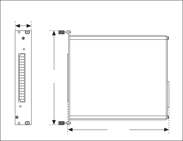

Appendix A Specifications
SCXI-1125 User Manual A-8 ni.com
Maximum Working Voltage
Maximum voltage rating refers to the signal voltage plus the common
mode voltage (Signal + common mode). Voltage of each input shall remain
within 300 V of ground.
Channel-to-earth .....................................300 V, Measurement Category II
Channel-to-channel.................................300 V, Measurement Category II
Cautions The SCXI-1125 is rated for Measurement Category II and is intended to carry
signal voltages no greater than 300 V. Do not use the SCXI-1125 for connection to signals
or for measurements within Categories III or IV.
When hazardous voltages (>42.4 Vpk/60 VDC) are present on any channel, all channels are
considered hazardous. Ensure that external wiring or any circuits connected to the device
are properly insulated from human contact.
Environmental
Operating temperature ............................0 to 50 °C
Storage temperature ................................–20 to 70 °C
Humidity.................................................10 to 90% RH, noncondensing
Maximum altitude...................................2,000 meters
Pollution Degree (indoor use only) ........2
Table A-2. Terminal Block Maximum Voltages
Module Signal Range Maximum Voltage and Category [Insulation]
SCXI-1313A 150 V 150 V, Measurement Category II
[channel-to-channel, channel-to-earth]
SCXI-1327 300 V 300 V, Measurement Category II
[bank-to-bank, bank-to-earth]
TBX-1316 600 V 600 V, Measurement Category II
[Basic; channel-to-channel]
1000 V 1000 V, Measurement Category I
[Basic; channel-to-channel]

Appendix A Specifications
© National Instruments Corporation A-9 SCXI-1125 User Manual
Safety
This product is designed to meet the requirements of the following
standards of safety for electrical equipment for measurement, control,
and laboratory use:
• IEC 61010-1, EN-61010-1
• UL 61010-1, CSA 61010-1
Note For UL and other safety certifications, refer to the product label or visit ni.com/
certification, search by model number or product line, and click the appropriate link
in the Certification column.
Electromagnetic Compatibility
This product is designed to meet the requirements of the following
standards of EMC for electrical equipment for measurement, control,
and laboratory use:
• EN 61326 EMC requirements; Minimum Immunity
• EN 55011 Emissions; Group 1, Class A
• CE, C-Tick, ICES, and FCC Part 15 Emissions; Class A
Notes For EMC compliance, operate this device according to product documentation.
For EMC compliance, operate this device with shielded cabling.
CE Compliance
This product meets the essential requirements of applicable European
Directives, as amended for CE marking, as follows:
• 2006/95/EC; Low-Voltage Directive (safety)
• 2004/108/EC; Electromagnetic Compatibility Directive (EMC)
Note Refer to the Declaration of Conformity (DoC) for this product for any additional
regulatory compliance information. To obtain the DoC for this product, visit ni.com/
certification, search by model number or product line, and click the appropriate link
in the Certification column.

Appendix A Specifications
SCXI-1125 User Manual A-10 ni.com
Environmental Management
National Instruments is committed to designing and manufacturing
products in an environmentally responsible manner. NI recognizes that
eliminating certain hazardous substances from our products is beneficial
not only to the environment but also to NI customers.
For additional environmental information, refer to the NI and the
Environment Web page at ni.com/environment. This page contains the
environmental regulations and directives with which NI complies, as well
as any other environmental information not included in this document.
Waste Electrical and Electronic Equipment (WEEE)
EU Customers At the end of their life cycle, all products must be sent to a WEEE recycling
center. For more information about WEEE recycling centers and National Instruments
WEEE initiatives, visit ni.com/environment/weee.htm.
⬉ᄤֵᙃѻક∵ᶧࠊㅵ⧚ࡲ⊩ ˄Ё
RoHS
˅
Ёᅶ᠋
National Instruments ヺড়Ё⬉ᄤֵᙃѻકЁ䰤ࠊՓ⫼ᶤѯ᳝ᆇ⠽䋼ᣛҸ (RoHS)DŽ
݇Ѣ National Instruments Ё RoHS ড়㾘ᗻֵᙃˈ䇋ⱏᔩ ni.com/environment/rohs_chinaDŽ
(For information about China RoHS compliance, go to ni.com/environment/rohs_china.)

© National Instruments Corporation B-1 SCXI-1125 User Manual
B
Using SCXI Channel Strings with
Traditional NI-DAQ (Legacy) 7.0
or Later
Note This appendix is not applicable if you use the virtual channels to configure and
measure the SCXI channels. Virtual channels are configured using MAX. If you use virtual
channels, you address the SCXI channels by specifying the channel name(s) in the channel
string input.
When using LabVIEW, and Visual Basic, the SCXI channel string
determines which SCXI channels are scanned and the scanning sequence.
The SCXI channel string allows you to take measurements from several
channels on one module with only one channel string entry. An array of
these channel string entries configures multiple modules for scanning.
When the application program runs, the channel string is used
for programming the channel information into the SCXI system.
The format of the channel string is as follows:
ob
x
! sc
y
! md
z
!
channels
where
•ob
x
is the onboard E/M Series DAQ device channel, with
x
representing a particular channel where the multiplexed channels are
sent. This value is 0 for E/M Series DAQ device channel 0 in a
single-chassis system. In a multichassis or remote chassis system, the
E/M Series DAQ device channel
x
corresponds to chassis number
n
– 1, where E/M Series DAQ device channel
x
is used for scanning
the nth chassis in the system.
•sc
y
is the SCXI chassis ID, where
y
is the number you chose when
configuring the chassis.
•md
z
is the slot position where the module is located, with
z
being the
particular slot number. The slots in a chassis are numbered from left to
right starting with 1.

Appendix B Using SCXI Channel Strings with Traditional NI-DAQ (Legacy) 7.0 or Later
SCXI-1125 User Manual B-2 ni.com
channels
is the list of channels that are scanned for module
z
. It can have
several formats:
•ob
x
! sc
y
! md
z
!
nx
, where
nx
is a single input channel.
•ob
x
! sc
y
! md
z
! (
n0
,
n2
), where
n0
,
n2
are individual input
channel that are not necessarily sequential.
•ob
x
! sc
y
! md
z
!
n0
:
n3
, where
n0
and
n3
represent an ascending
sequential list of input channels, inclusive.
•ob
x
! sc
y
! md
z
! (
n0
,
n2
,
n3
:
n4
,
n1
,
n5
,
n2
), where
n0
,
n2
, and
n5
represent single channels, not necessarily sequential,
and
n3
and
n4
represent the endpoints of an ascending sequential list
of channels, inclusive. In this case, channels
n1
and
n2
are explicitly
repeated in the channel list.
Notes Using parenthesis surrounding multiple channels in a channel string is important
for correct scanning operation of the SCXI channels.
In a single-chassis system, the ob
x
! specifier is optional and causes the gains on the
module and E/M Series DAQ device to be automatically set to fit the input limits
parameter. When this specifier is omitted, the default gain on the E/M Series DAQ device,
usually the lowest gain, is used, but the SCXI-1125 gain is adjusted to fit the input limits.
NI recommends using the ob
x
! specifier.
Repeating channels or having channels out of sequence in a scan list is not supported on
all SCXI modules. Refer to the manual of each module for information on this feature,
which is referred to as flexible scanning or random scanning.
For more information about using SCXI channel string, refer to the
LabVIEW Measurements Manual and SCXI-1125 shipping examples.

© National Instruments Corporation C-1 SCXI-1125 User Manual
C
Removing the SCXI-1125
This appendix explains how to remove the SCXI-1125 from MAX and an
SCXI chassis.
Note Figure C-1 shows an SCXI chassis, but the same steps are applicable to a PXI/SCXI
combination chassis.
Removing the SCXI-1125 from MAX
To remove a module from MAX, complete the following steps after
launching MAX:
1. Expand Devices and Interfaces to display the list of installed devices
and interfaces.
2. Expand NI-DAQmx Devices and/or Traditional NI-DAQ Devices to
display the chassis.
3. Expand the appropriate chassis to display the installed modules.
4. Right-click the module or chassis you want to delete and click Delete.
5. You are presented with a confirmation window. Click Yes to continue
deleting the module or chassis or No to cancel this action.
Note Deleting the SCXI chassis deletes all modules in the chassis. All configuration
information for these modules is also deleted.
The SCXI chassis and/or SCXI module(s) should now be removed from the
list of installed devices in MAX.
Removing the SCXI-1125 from a Chassis
Consult the documentation for the chassis and accessories for additional
instructions and precautions. To remove the SCXI-1125 module from an
chassis, complete the following steps while referring to Figure C-1:
1. Power off the chassis. Do not remove the SCXI-1125 module from a
chassis that is powered on.
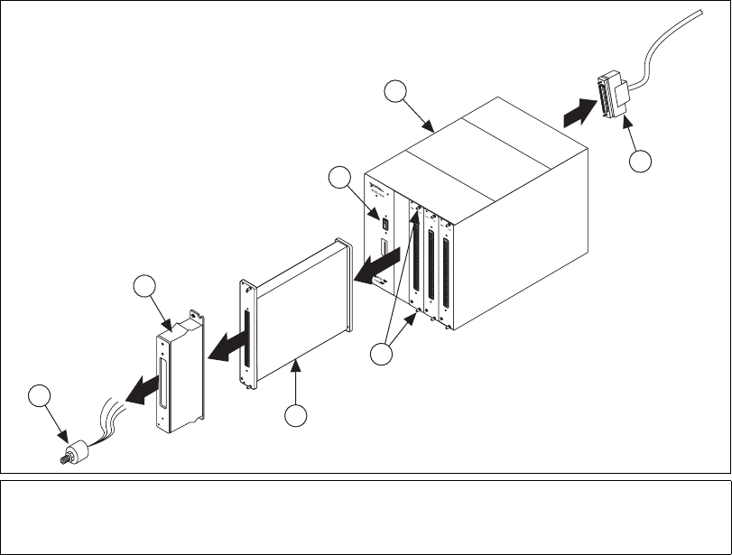
Appendix C Removing the SCXI-1125
SCXI-1125 User Manual C-2 ni.com
2. If the SCXI-1125 is the module cabled to the E Series DAQ device,
disconnect the cable.
3. Remove any terminal block that connects to the SCXI-1125.
4. Rotate the thumbscrews that secure the SCXI-1125 to the chassis
counterclockwise until they are loose, but do not completely remove
the thumbscrews.
5. Remove the SCXI-1125 by pulling steadily on both thumbscrews until
the module slides completely out.
Figure C-1. Removing the SCXI-1125
1Cable
2SCXI Module Thumbscrews
3SCXI-1125
4Sensor
5Terminal Block
6SCXI Chassis Power Switch
7SCXI Chassis
MAINFRAME
SCXI
3
2
5
4
3
2
1
ADDRESS
1
6
7
SCXI 1100
4
5

© National Instruments Corporation D-1 SCXI-1125 User Manual
D
Common Questions
This appendix lists common questions related to the use of the SCXI-1125.
The SCXI-1125 is backward compatible with the SCXI-1120, but what
are the major differences between the SCXI-1120 and the SCXI-1125?
Table D-1 compares the major specifications and features of the two
modules. Other specifications and features of the SCXI-1125 are the same
or very similar to the SCXI-1120.
Table D-1. Comparison of the SCXI-1125 with the SCXI-1120
Feature SCXI-1120 SCXI-1125
Analog input 8 8
Input range ±5 V, ±250 V with SCXI-1327 ±5 V, ±300 V with SCXI-1327,
±1000 VDC with TBX-1316
Isolation 250 Vrms 300 Vrms
Gains 1, 2, 5, 10, 20, 50, 100, 200, 250, 500,
1000, and 2000 jumper selectable
1, 2, 5, 10, 20, 50, 100, 200, 250, 500,
1000, and 2000 software selectable
Filters 4 Hz or 10 kHz jumper selectable 4 Hz or 10 kHz software selectable
Autozero Not supported Software configurable and scannable
Calibration Manually rotateable potentiometers
for one-point offset calibration
Software internal one-point offset
calibration, software external
two-point offset and gain calibration,
and onboard calibration constant
storage in EEPROM
Scanning 333 kS/s with consecutive channels 333 kS/s with nonconsecutive and
repeating channels (random scanning)
CJC scanning M TEMP (non-scannable) or
D TEMP (direct channel)
M TEMP, CJ TEMP (scannable)
Offset error ±6 µV ± 3 mV/gain 0.2 mV/gain typical
Gain error ±0.2% typ, ±0.6% max ±0.03% typ, ±0.08% max
Appendix D Common Questions
SCXI-1125 User Manual D-2 ni.com
Which version of NI-DAQ is needed to work with the SCXI-1125 and
how do I get the most current version of NI-DAQ?
You must have NI-DAQ 7.0 or later. Visit ni.com and follow the link,
Download Software»Drivers and Updates»Search Drivers and
Updates, and type in the keyword NI-DAQ to find the latest version of
NI-DAQ for your operating system.
I have gone over the Verifying the SCXI-1125 Installation in Software in
Chapter 1, About the SCXI-1125, yet I still cannot correctly test and
verify that my SCXI-1125 is working. What should I do now?
Unfortunately, there always exists the chance that something is not
operating correctly in your system, or the combination of the components
in your system is not operating correctly together. You may now have to call
or e-mail a technical support representative.
The technical support representative will often suggest additional
troubleshooting measures to try in order to isolate the problem. If
requesting technical support by phone, have your system near at hand so
that you can try these measures immediately.
Can I use the unused analog input channels of the E/M Series DAQ
device if I am directly cabled to the SCXI-1125?
It depends. The SCXI-1125 always outputs channels 1 through 7 to the rear
signal connector to permit parallel mode scanning. If you are using a
16-channel (8 differential inputs) E/M Series DAQ device, all E/M Series
DAQ channels are unusable for general-purpose analog input. If you have
a module in the chassis that does not have parallel mode, connect the
E/M Series DAQ device to it and use a breakout connector to connect to the
unused channels on the E/M Series DAQ device. If you are directly
connected to a higher input channel device, such as a 64-channel
(32 differential inputs) E/M Series DAQ device, only the lower
eight differential inputs are unusable.
Which digital lines are unavailable on the E/M Series DAQ device if I
am cabled to an SCXI-1125 module?
Table D-2 shows the digital lines that are used by the SCXI-1125 for
communication and scanning. These lines are unavailable for
general-purpose digital I/O if the SCXI-1125 is connected to the
E/M Series DAQ device.

Appendix D Common Questions
© National Instruments Corporation D-3 SCXI-1125 User Manual
In LabVIEW, can I use different input limits for the same SCXI-1125
channel if I repeat the channel in the SCXI channel string array?
No, the SCXI-1125 cannot dynamically change the gain settings during
scanning. Therefore, channels with similar input ranges should be grouped
together in the channel string array. Make sure that repeated channels in
different indices of the channel string array have the same input limits in
the corresponding input limits array.
In LabVIEW, can I use virtual channels with parallel mode channels
on the SCXI-1125?
Yes, virtual channels work with parallel mode operation on the SCXI-1125.
The E/M Series DAQ device must be directly connected to the module in
parallel mode operation. Also, virtual channels that use built-in CJC are
disabled and cannot be used in parallel mode.
In LabVIEW, can I use the calgnd channel string when the SCXI-1125
is in parallel mode?
Yes, you can autozero the SCXI-1125 in LabVIEW when using the module
in parallel mode.
Table D-2. Digital Signals on the SCXI-1125
Traditional
DAQ Signal
Name
DAQmx
Signal Name
SCXI Signal
Name
50-Pin
Connector
68-Pin
Connector Direction
DIO0 P0.0 SER DAT IN 25 52 Output
DIO4 P0.4 SER DAT OUT 26 19 Input
DIO1 P0.1 DAQ D*/A 27 17 Output
DIO2 P0.2 SLOT 0 SEL* 29 49 Output
SCANCLK AI HOLD
COMP,
AI HOLD
SCAN CLK 36 46 Output
EXTSROBE* EXTSROBE SER CLK 37 45 Output
STARTSCAN AI SAMP
CLK,
AI SAMP
SYNC* 46 38 Output
Appendix D Common Questions
SCXI-1125 User Manual D-4 ni.com
In LabVIEW, can I use a VI to change my filter setting?
In NI-DAQmx, you can change the filter settings using a DAQmx Channel
property node. In Traditional NI-DAQ (Legacy), there is no VI available to
do this. You must use the configuration utility in MAX to configure the
filter setting of each channel.
In C, can I randomly scan the SCXI-1125 using low level Traditional
NI-DAQ (Legacy) function calls?
No, using C, you can scan only consecutive channels using traditional
SCXI channel programming. Refer to the NI-DAQ function reference
manual for more details on SCXI scanning.
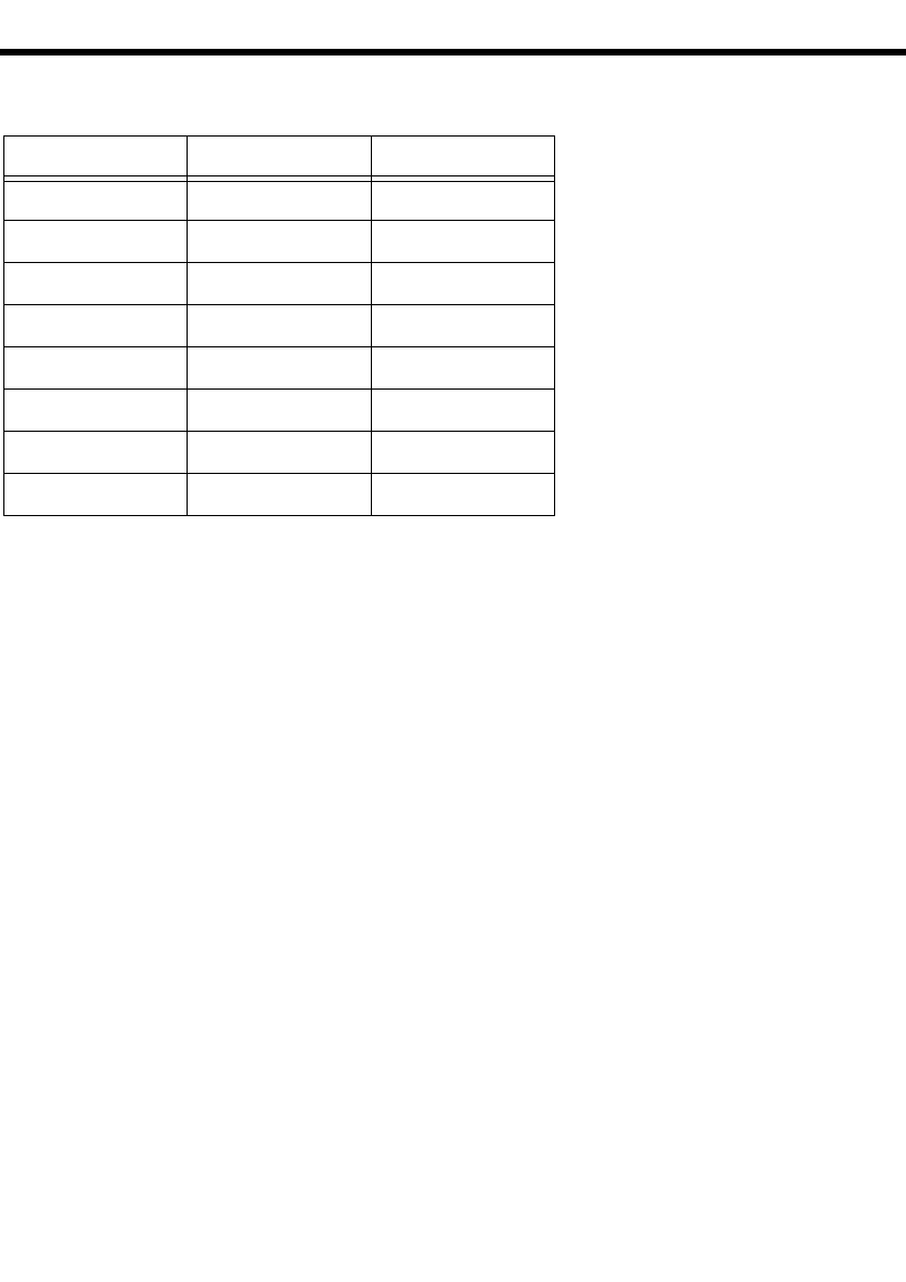
© National Instruments Corporation G-1 SCXI-1125 User Manual
Glossary
Symbol Prefix Value
ppico10
– 12
nnano10
– 9
μmicro 10
– 6
m milli 10 – 3
k kilo 10 3
Mmega10
6
Ggiga10
9
Ttera10
12
Numbers/Symbol
° Degrees.
≥Greater than or equal to.
≤Less than or equal to.
ΩOhms.
/Per.
% Percent.
± Plus or minus.
+5 V (signal) +5 VDC source signal.
Glossary
SCXI-1125 User Manual G-2 ni.com
A
A/D analog-to-digital
absolute accuracy The maximum difference between the measured value from a data
acquisition device and the true voltage applied to the input, typically
specified as ± voltage.
AC alternating current
ADC analog-to-digital converter—An electronic device, often an integrated
circuit, that converts an analog voltage to a digital number.
ADE application development environment—A software environment
incorporating the development, debug, and analysis tools for software
development.
AI GND analog input ground
AI HOLD COMP,
AI HOLD
clock that triggers scanning
amplification A type of signal conditioning that improves accuracy in the resulting
digitized signal by increasing signal amplitude relative to noise.
autozero A procedure for eliminating offsets generated by an amplifier stage.
B
bandwidth The range of frequencies present in a signal, or the range of frequencies to
which a measuring device can respond.
bias current The small input current flowing into or out of the input terminals of an
amplifier.
bit one binary digit, either 0 or 1
BNC Bayonet-Neill-Concelman—A type of coaxial connector used in situations
requiring shielded cable for signal connections and/or controlled
impedance applications.
Glossary
© National Instruments Corporation G-3 SCXI-1125 User Manual
C
CCelsius
CE Conformité Européenne—The European emissions control standard. The
CE mark certifies that a product complies to relevant CE regulations. CE is
a common standard for all countries in the EU (European Union).
CH channel
channel Pin or wire lead to which you apply or from which you read an analog or
digital signal. Analog signals can be single-ended or differential. For digital
signals, channels group to form ports. Ports usually consist of either four or
eight digital channels.
chassis The enclosure that houses, powers, and controls SCXI modules.
CJ TEMP cold-junction temperature sensor signal
CJC cold-junction compensation
CLK clock input signal
CMRR common-mode rejection ratio—A measure of the capability of an
instrument to reject a signal that is common to both input leads.
code width The smallest detectable change in an input voltage of a DAQ device.
cold-junction
compensation
A method of compensating for inaccuracies in thermocouple circuits.
common-mode voltage Voltage that appears on both inputs of a differential amplifier.
cutoff frequency The frequency at which the filter attenuates the input 3 dB, or half of its
original power.
D
D/A digital-to-analog
D*/A data/Address
D GND digital ground signal
Glossary
SCXI-1125 User Manual G-4 ni.com
DAQ Data acquisition—(1) collecting and measuring electrical signals from
sensors, transducers, and test probes or fixtures and inputting them to a
computer for processing; (2) collecting and measuring the same kinds of
electrical signals with A/D and/or DIO boards plugged into a computer, and
possibly generating control signals with D/A and/or DIO boards in the
same computer.
DAQ device A device that collects signals for data acquisition devices. Examples are
MIO and 1200 boards.
dB decibel—The unit for expressing a logarithmic measure of the ratio of
two signal levels: dB = 20 log10 (V1/V2), for signals in volts.
DC direct current
device A plug-in data acquisition board, module, card, or pad that can contain
multiple channels and conversion devices.
differential input An input circuit that actively responds to the difference between two
terminals, rather than the difference between one terminal and ground.
DIN deutsche Industrie Norme
DIO digital I/O
DMM digital multimeter—A digital instrument capable of measuring several
different fundamental electrical characteristics, most often voltage,
resistance, and current.
E
EEPROM electrically erasable programmable read-only memory—ROM that can be
erased with an electrical signal and reprogrammed.
EMC electromechanical compliance
EMI electromagnetic interference
Glossary
© National Instruments Corporation G-5 SCXI-1125 User Manual
F
filtering A type of signal conditioning that allows you to remove unwanted signal
components from the signal you are trying to measure.
FSR full-scale range
G
gain The factor by which a signal is amplified, sometimes expressed in decibels.
gain accuracy A measure of deviation of the gain of an amplifier from the ideal gain.
gain error See gain accuracy.
GND ground
H
Hz hertz
I
I/O input/output—The transfer of data to/from a computer system involving
communications channels, operator interface devices, and/or data
acquisition and control interfaces.
in. inch
input bias current The current that flows into the inputs of a circuit.
input impedance The measured resistance and capacitance between the input terminals of a
circuit.
Glossary
SCXI-1125 User Manual G-6 ni.com
isolation A type of signal conditioning in which you isolate the transducer signals
from the computer for safety purposes. Isolating the signals protects you
and your computer from large voltage spikes and makes sure the
measurements from the DAQ device are not affected by differences in
ground potentials.
isothermal Maintenance of constant temperature across an area. Isothermal
construction of terminal blocks increases thermocouple measurement
accuracy.
K
K kelvin
L
linearization A type of signal conditioning in which software linearizes the voltage levels
from transducers, so the voltages can be scaled to measure physical
phenomena.
M
m meters
M (1) Mega, the standard metric prefix for 1 million or 106, when used with
units of measure such as volts and hertz; (2) mega, the prefix for 1,048,576,
or 220, when used with B to quantify data or computer memory.
M TEMP multiplexed temperature sensor signal. See also CJ TEMP.
max Minimum.
min (1) minutes
(2) minimum
MIO multifunction I/O
multiplex To assign more than one signal to a channel.
Glossary
© National Instruments Corporation G-7 SCXI-1125 User Manual
multiplexed mode An SCXI operating mode in which analog input channels are multiplexed
into one module output so that your cabled DAQ device has access to the
module’s multiplexed output as well as the outputs on all other multiplexed
modules in the chassis through the SCXIbus.
mux multiplexer—A switching device with multiple inputs that sequentially
connects each of its inputs to its single output, typically at high speeds, in
order to measure several signals with a single analog-to-digital converter.
N
NC not connected
NI-DAQ The driver software needed to use National Instruments DAQ devices and
SCXI components.
noise Analog. Unwanted signals. Noise comes from both external sources, such
as the AC power line, motors, generators, transformers, fluorescent lights,
soldering irons, CRT displays, computers, electrical storms, welders, and
radio transmitters, and internal sources, such as digital clocks,
microprocessors, and switched mode power supplies. Video system noise
can take various forms, including snow, which is a random video noise. It
corrupts signals you are trying to send or receive.
O
offset error A constant error added to a measurement along the whole transfer curve.
For example, in mx+b, the offset error is b.
offset null
compensation
The provision in strain-gauge signal conditioning hardware to remove the
unwanted offset voltage present at the output of a strain-gauge bridge when
no strain is applied.
P
parallel mode A type of SCXI operating mode in which the module sends each of its
output channels directly to a separate analog input channel of the DAQ
device connected to the module.
passband The range of input frequencies that are passed to the filter output without
attenuation.
Glossary
SCXI-1125 User Manual G-8 ni.com
ppm parts per million
PXI A rugged, open system for modular instrumentation based on CompactPCI,
with special mechanical, electrical, and software features. The PXIbus
standard was originally developed by National Instruments in 1997, and is
now managed by the PXIbus Systems Alliance.
R
resolution The smallest signal increment that can be detected by a measurement
system. Resolution can be expressed in bits, in proportions, or in percent of
full scale. For example, a system has 12-bit resolution, one part in 4,096
resolution, and 0.0244% of full scale.
RMA return Material Authorization
rms root mean square
RSVD reserved bit/signal
RTI referred to input—Calculates a specification relative to the input range.
S
s seconds
sample An instantaneous measurement of a signal, normally using an
analog-to-digital converter in an E Series DAQ device.
sample rate The number of samples a system takes over a given time period, usually
expressed in samples per second.
scan One or more analog or digital input samples. Typically, the number of input
samples in a scan is equal to the number of channels in the input group. For
example, one pulse from the scan clock produces one scan which acquires
one new sample from every analog input channel in the group.
SCANCLK Scan clock signal used to increment the next channel after each E Series
DAQ device analog-to-digital conversion.
Glossary
© National Instruments Corporation G-9 SCXI-1125 User Manual
SCXI Signal Conditioning eXtensions for Instrumentation—the National
Instruments product line for conditioning low-level signals within an
external chassis near sensors so only high-level signals are sent to DAQ
boards in the noisy PC environment.
SCXIbus The analog bus where SCXI analog signals are routed.
SER CLK A serial clock signal used to synchronize digital data transfers over the SER
DAT IN and SER DAT OUT lines.
SER DAT IN serial data input signal
SER DAT OUT serial data out to cabled DAQ device
sensor A device that responds to a physical stimulus (heat, light, sound, pressure,
motion, flow, and so on), and produces a corresponding electrical signal.
Primary characteristics of sensors are sensitivity, frequency range, and
linearity.
settling time The time required for an amplifier, relays, or other circuits to reach a stable
mode of operation.
shunt See autozero.
shunt calibration The method of calibrating the gain of strain-gauge data acquisition channel
by placing a resistor of known value in parallel with a bridge element.
signal conditioning The manipulation of signals to prepare them for digitizing.
Slot 0 The first slot in a VXI or SCXI system.
strain The relative deformation of an object subjected to stress. Hence, strain is
dimensionless.
SYNC synchronization pulse for scanning
system noise A measure of the amount of noise seen by an analog circuit or an ADC
when the analog inputs are grounded.
Glossary
SCXI-1125 User Manual G-10 ni.com
T
thermocouple A temperature sensor created by joining two dissimilar metals. The
junction produces a small voltage as a function of the temperature.
typ typical
U
UL Underwriters Laboratory
V
Vvolts
VDC volts direct current
VI virtual instrument—(1) a combination of hardware and/or software
elements, typically used with a PC, that has the functionality of a classic
stand-alone instrument (2) a LabVIEW software module (VI), which
consists of a front panel user interface and a block diagram program.
virtual channels Channel names that can be defined outside of the application and used
without having to perform scaling operations. Virtual channels are called
custom channels in MAX 3.0 and later.
voltage excitation A source that supplies the voltage needed by a sensor for its proper
operation.
Vrms volts, root mean square
W
working isolation A level of protection pertaining to a working voltage.
working voltage The highest voltage that should be applied to a product in normal use,
normally well under the breakdown voltage for safety margin.

© National Instruments Corporation I-1 SCXI-1125 User Manual
Index
A
AC and DC voltage connections, 2-1
AC-coupling, 2-4
floating AC-coupled signal connection
(figure), 2-4
floating signal, 2-3
floating signal connection (figure), 2-3
front signal connector
figure, 2-6
table, 2-6
ground-referenced AC-coupled signal
connection (figure), 2-4
ground-referenced signal, 2-2
ground-referenced signal connection
(figure), 2-2
analog input channels on DAQ device, D-2
C
C language
multiplexed scanning operations, 5-27
parallel scanning operations, 5-28
scanning channels, D-4
calibration
gain values and input limits (table), 5-31
one-point offset calibration, 5-31
overview, 5-30
two-point gain and offset calibration, 5-32
channel string
calgnd channel string, D-3
SCXI, 5-25
virtual, 5-26
channels
C language scanning, D-4
questions about, D-3
unused analog input channels on DAQ
device, D-2
common questions, D-1
configuration
troubleshooting self-test verification, 1-7
configuration settings
filter bandwidth, 3-1, 4-2
gain, 3-1, 4-1
connecting SCXI-1125 to DAQ device
See also DAQ devices
for parallel scanning, 1-5
connectors
front signal connector
pin assignments
figure, 2-6
table, 2-6
rear signal connector
description, 2-7
pin assignments
figure, 2-8
table, 2-8
conventions used in the manual, iv
D
DAQ device
connecting with SCXI-1125
for parallel scanning, 1-5
unavailable digital lines, D-2
unused analog input channels, D-2
DAQ devices
connecting to SCXI-1125 for multiplexed
scanning
in PXI combination chassis, 1-4, 3-2
in SCXI chassis, 1-4, 3-2
DC voltage connections. See AC and DC voltage
connections
Index
SCXI-1125 User Manual I-2 ni.com
digital lines, unavailability on DAQ device,
D-2
digital signals on SCXI-1125 (table), D-3
documentation
conventions used in the manual, iv
E
electromagnetic compatibility
specifications, A-9
environmental specifications, A-8
F
filter setting, changing, D-4
filters
bandwidth configuration, 3-1, 4-2
floating signal connections
AC-coupled signal connection
(figure), 2-4
description, 2-3
front signal connector
pin assignments
figure, 2-6
table, 2-6
G
gain
configuration, 3-1, 4-1
ground-referenced signal connections
AC-coupled signal connection
(figure), 2-4
description, 2-2
H
high-voltage measurements, 5-4
I
input characteristics, A-1
installation
connecting SCXI-1125 to DAQ device for
parallel scanning, 1-5
connecting to DAQ device for
multiplexed scanning
in PXI combination chassis, 1-4, 3-2
in SCXI chassis, 1-4, 3-2
into SCXI chassis, 1-4
removing SCXI-1125
from Measurement & Automation
Explorer, C-1
from SCXI chassis, C-1
L
LabVIEW
multiplexed scanning operations
SCXI channel string, 5-25
virtual channel string, 5-26
parallel scanning operations, 5-28
low-level DAQ functions, in multiplexed
scanning, 5-28
M
maximum working voltage, A-8
Measurement & Automation Explorer
removing SCXI-1125, C-1
self-test verification
troubleshooting, 1-7
multiplexed mode
operating in, 4-2
performing scans, 5-27
C and low-level DAQ functions, 5-28
rear signal connector pin assignments
figure, 2-8
table, 2-8
Index
© National Instruments Corporation I-3 SCXI-1125 User Manual
theory of multiplexed hardware
operation, 4-3
using software for scanning operations
LabVIEW and SCXI channel
string, 5-25
LabVIEW and virtual channel
string, 5-26
multiplexed mode operation
connecting to SCXI-1125 for DAQ device
in PXI combination, 1-4, 3-2
in SCXI chassis, 1-4, 3-2
N
NI-DAQ version required, D-2
P
parallel mode
connecting SCXI-1125 to DAQ
device, 1-5
theory of parallel hardware operation, 4-4
using software for scanning
C and parallel mode, 5-29
LabVIEW and parallel mode, 5-28
physical specifications, A-7
pin assignments
front connector (table), 2-6
PXI combination chassis, 1-4, 3-2
R
rear signal connector
description, 2-7
pin assignments
figure, 2-8
table, 2-8
regulatory compliance specifications, A-9
removing SCXI-1125
from Measurement & Automation
Explorer, C-1
from SCXI chassis, C-1
S
safety specifications, A-9
SCXI channel string, 5-25
SCXI chassis
connecting SCXI-1125 to DAQ device,
1-4, 3-2
SCXI-1125
calibration, 5-30
common questions, D-1
digital signals (table), D-3
multiplexed mode, 4-2
parallel mode, 4-3
signal connections, 2-1
specifications, A-1
self-test verification
troubleshooting, 1-7, D-2
signal connections
See also connectors
AC and DC voltage connections, 2-1
AC-coupling, 2-4
floating AC-coupled signal
connection (figure), 2-4
floating signal, 2-3
floating signal connection
(figure), 2-3
front signal connector (figure), 2-6
ground-referenced AC-coupled
signal connection (figure), 2-4
ground-referenced signal, 2-2
ground-referenced signal connection
(figure), 2-2
digital signals (table), D-3
Index
SCXI-1125 User Manual I-4 ni.com
front connector
pin assignments (table), 2-6
overview, 2-1
temperature sensor connection, 2-7
software
multiplexed scanning operations, 5-24
LabVIEW and SCXI channel
string, 5-25
LabVIEW and virtual channel
string, 5-26
parallel scanning operations
C and parallel mode, 5-29
LabVIEW and parallel mode, 5-28
specifications
electromagnetic compatibility, A-9
environmental, A-8
input characteristics, A-1
maximum working voltage, A-8
physical, A-7
regulatory compliance, A-9
safety, A-9
stability, A-6
transfer characteristics, A-6
stability specifications, A-6
T
temperature measurements using
thermocouples, 5-1
accurate method for temperature
determination, 5-2
guide for calculating overall temperature
error, 5-3
overview, 5-1
temperature sensor connection, 2-7
thermocouples for temperature measurements.
See temperature measurements using
thermocouples
transfer characteristics, A-6
troubleshooting
NI resources. See common questions
self-test verification, 1-7
V
verifying and self-testing the configuration
troubleshooting, 1-7
virtual channel string, 5-26
