Nauticast NAUTICASTA2 NAUTICAST A2 User Manual
Nauticast GmbH NAUTICAST A2 Users Manual
UserManual.wiki
>
Nauticast
>
NAUTICASTA2 User Manual
Users Manual
Navigation menu
Upload a User Manual
Namespaces
Wiki Guide
HTML
PDF
Info
Views
User Manual
Discussion / Help
Navigation
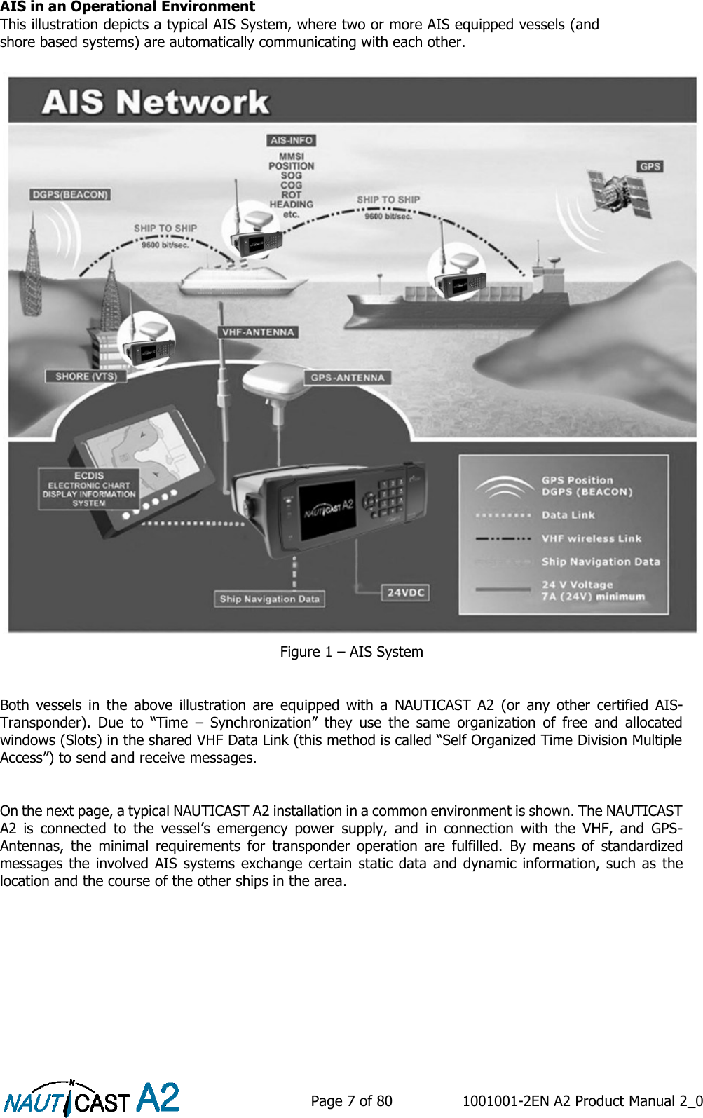
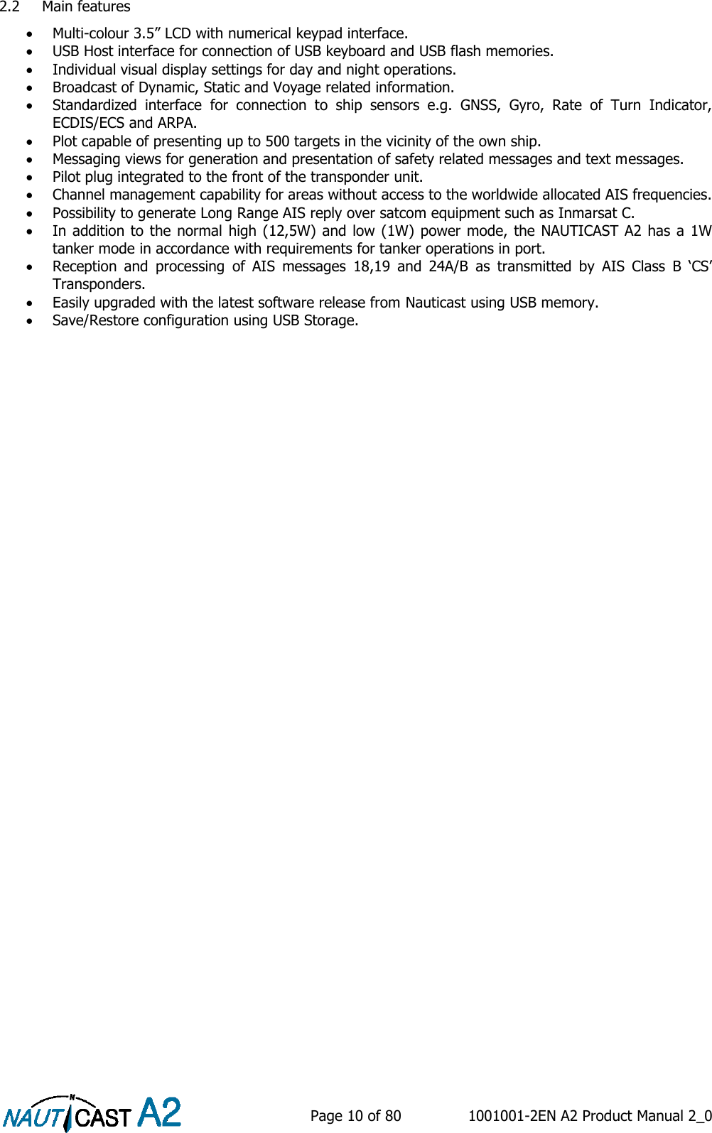
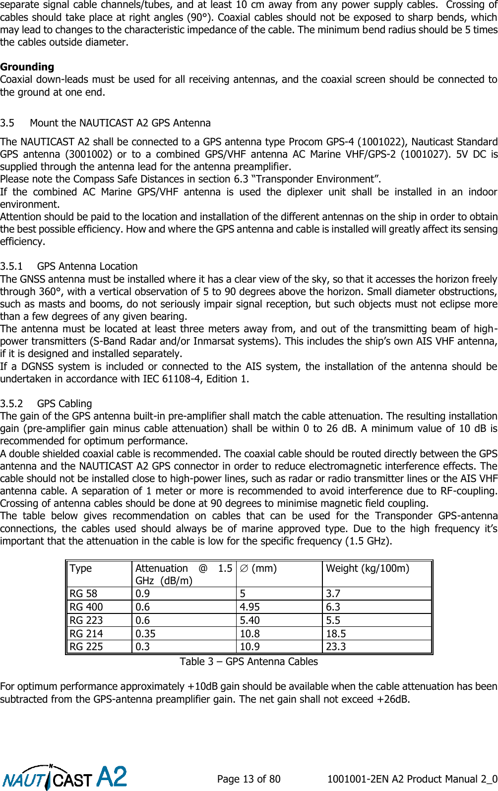
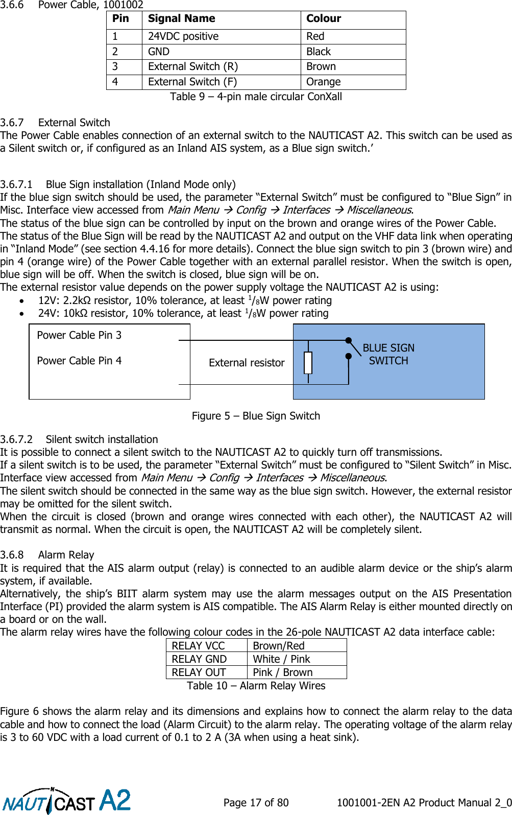
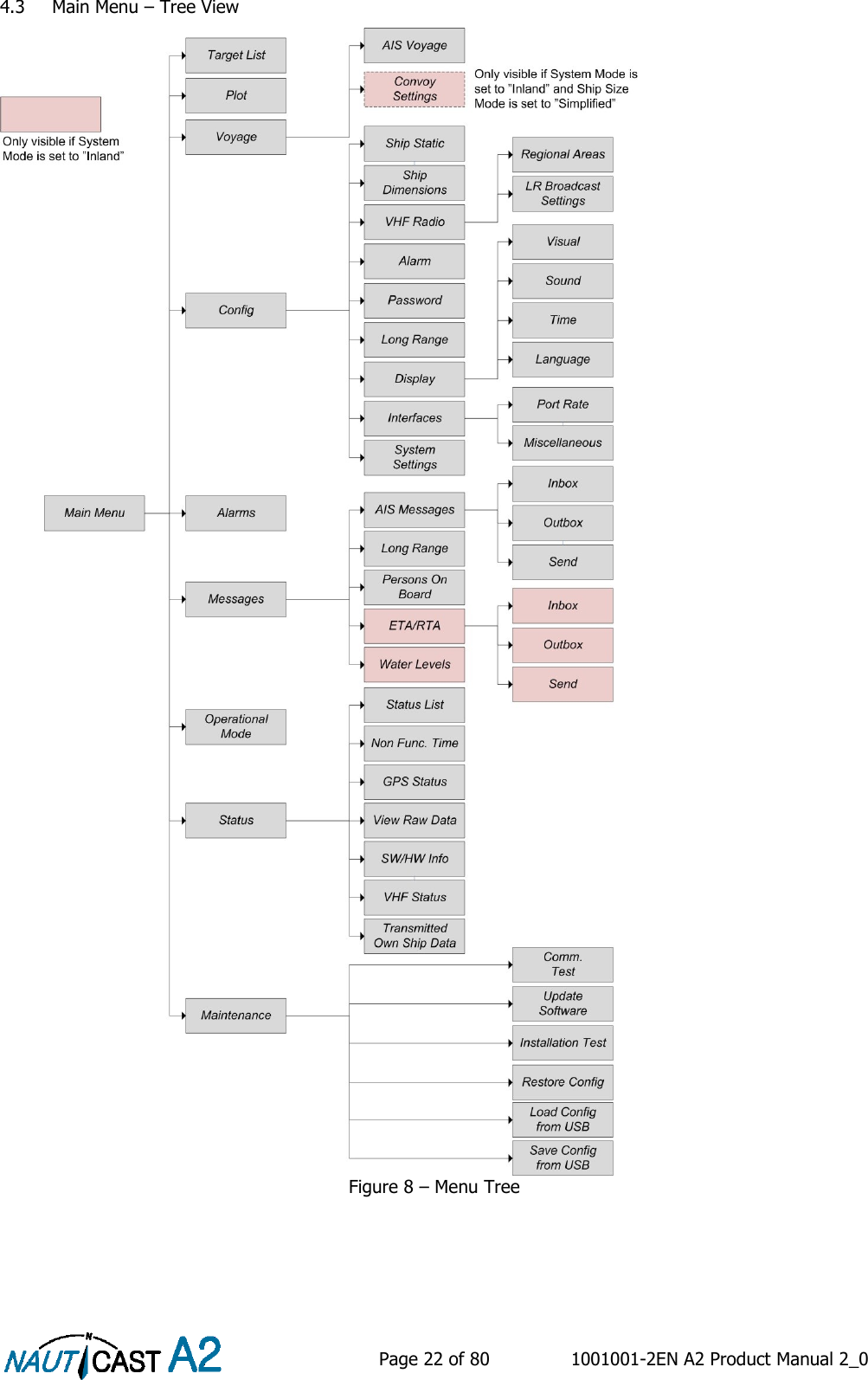
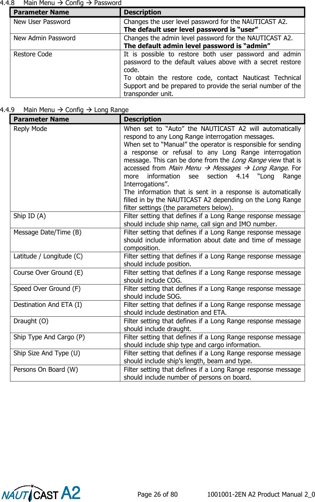
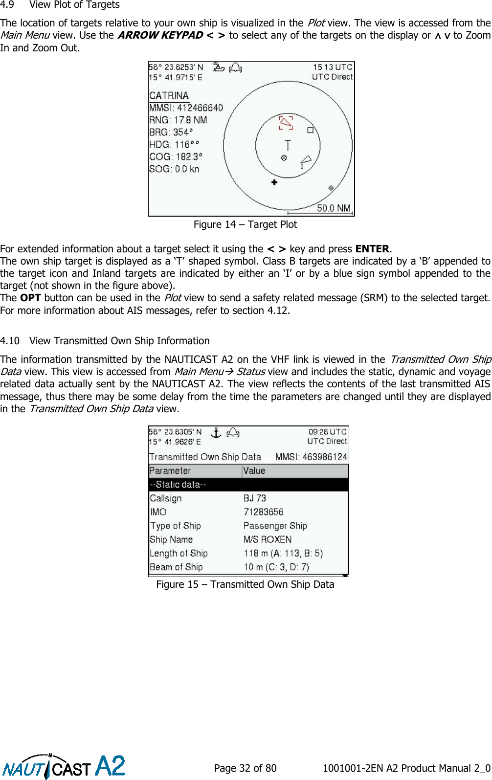
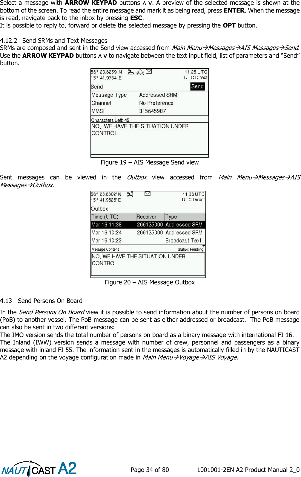
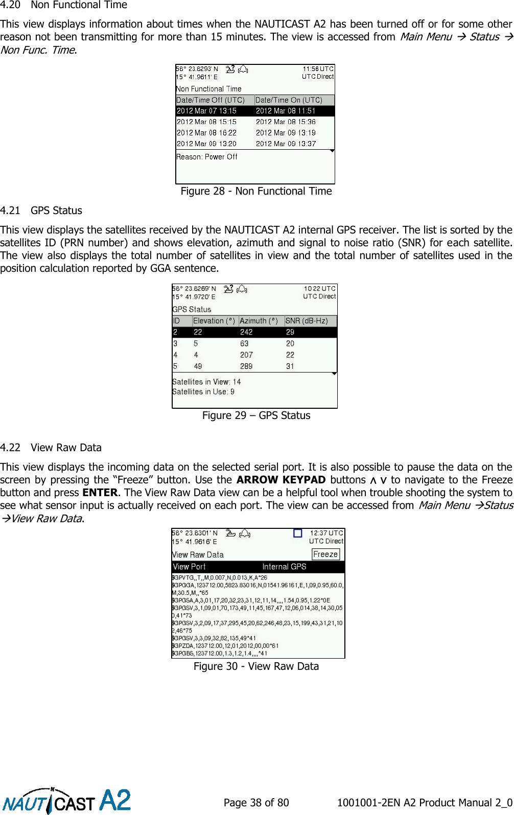
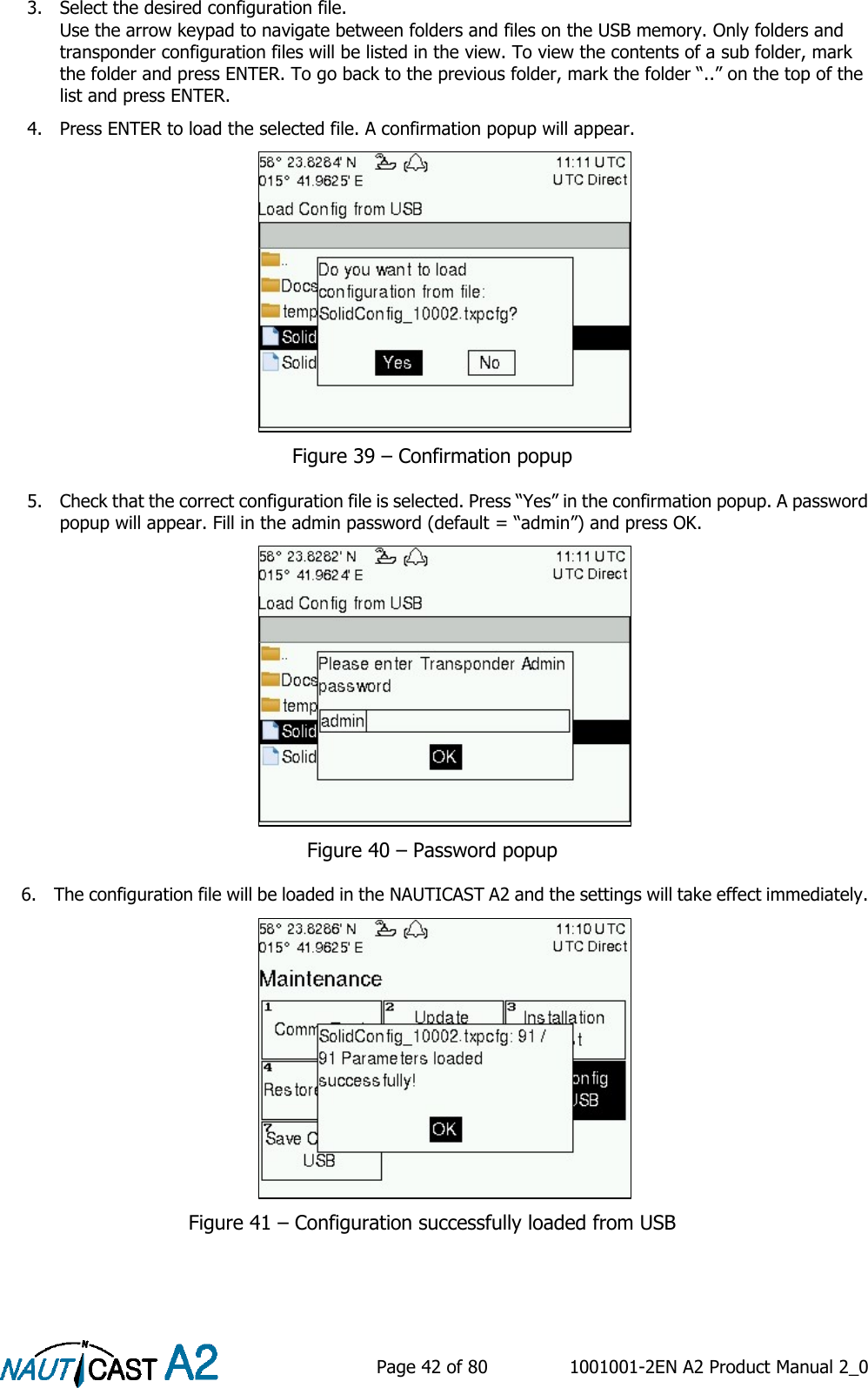
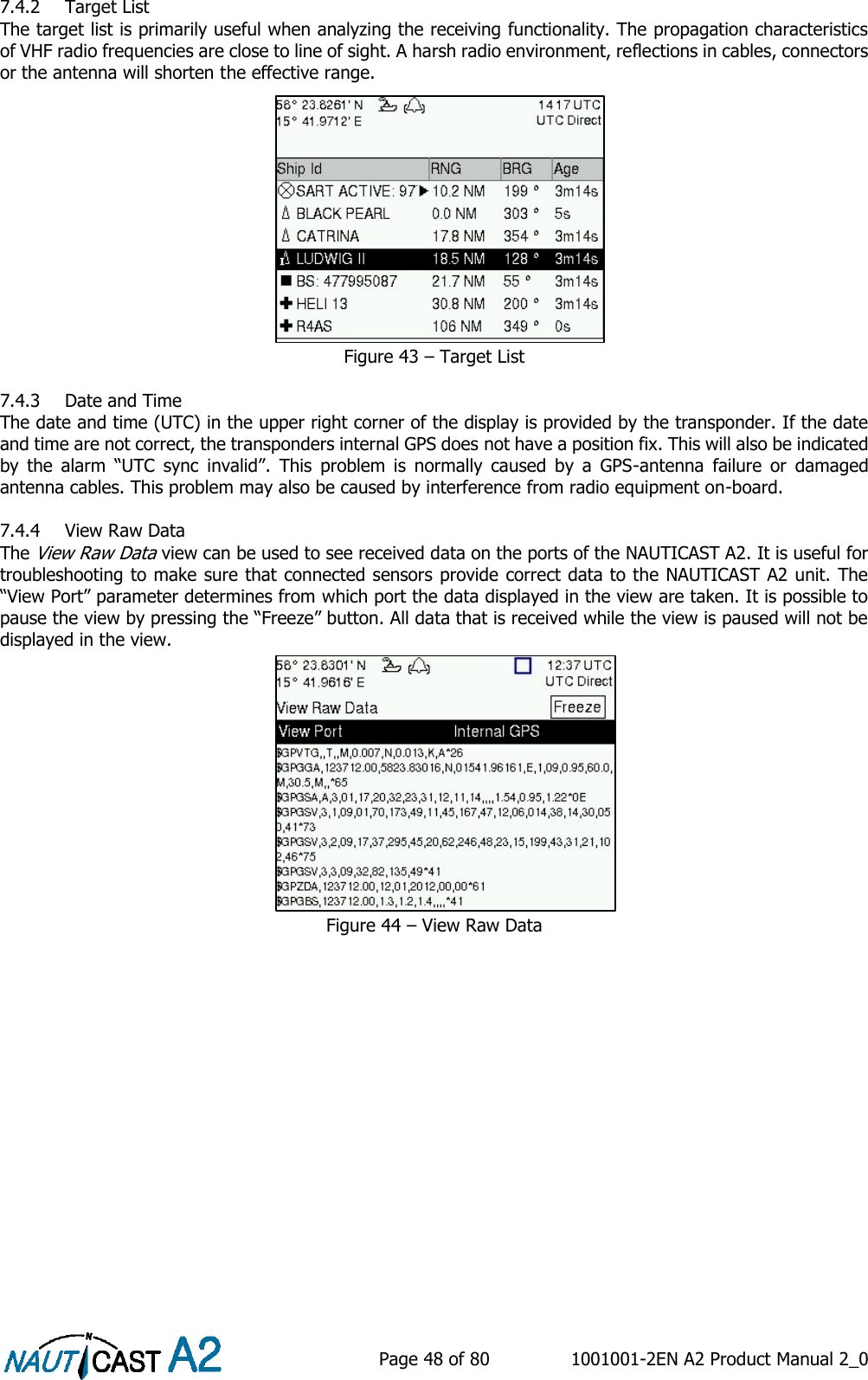
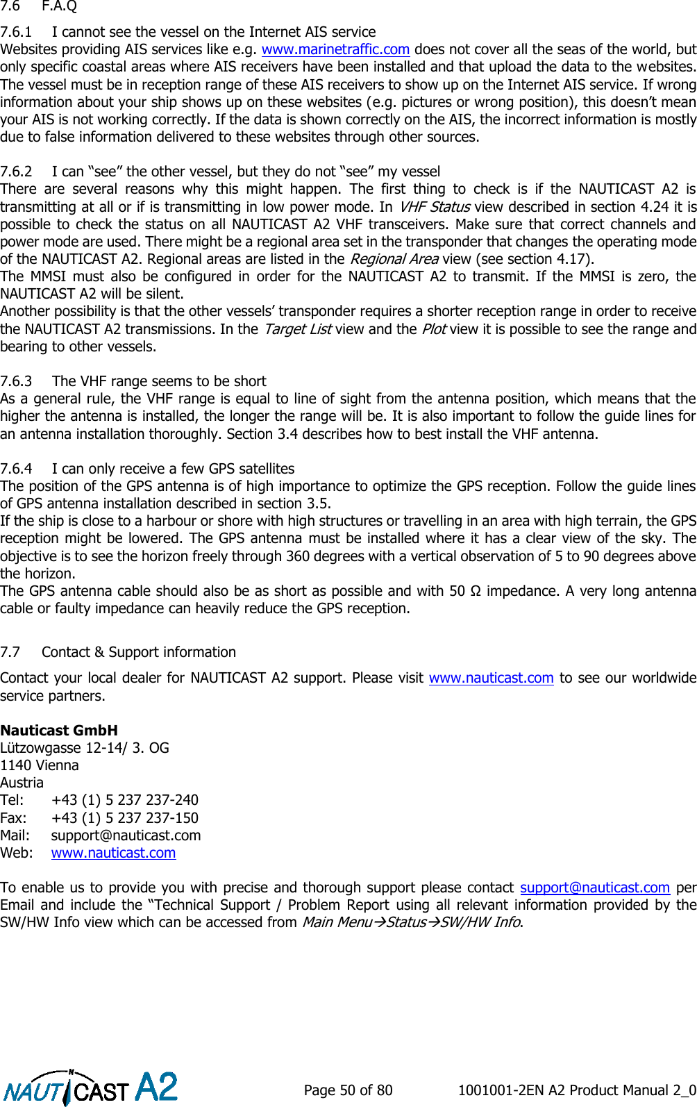
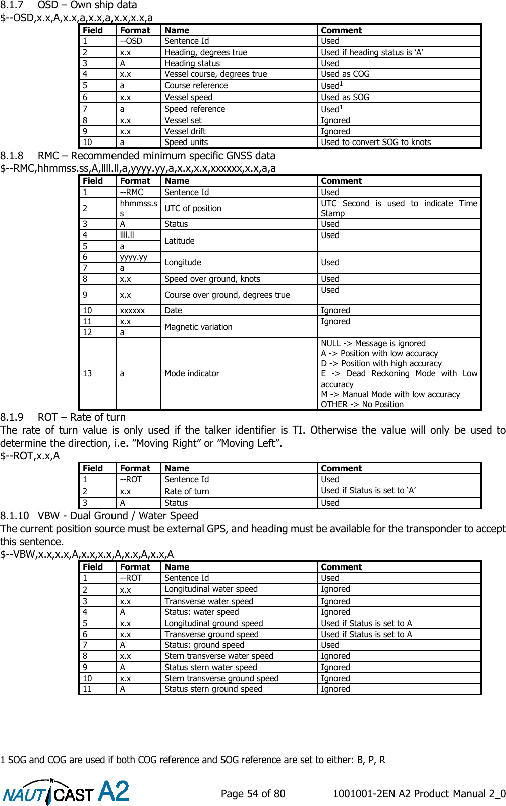
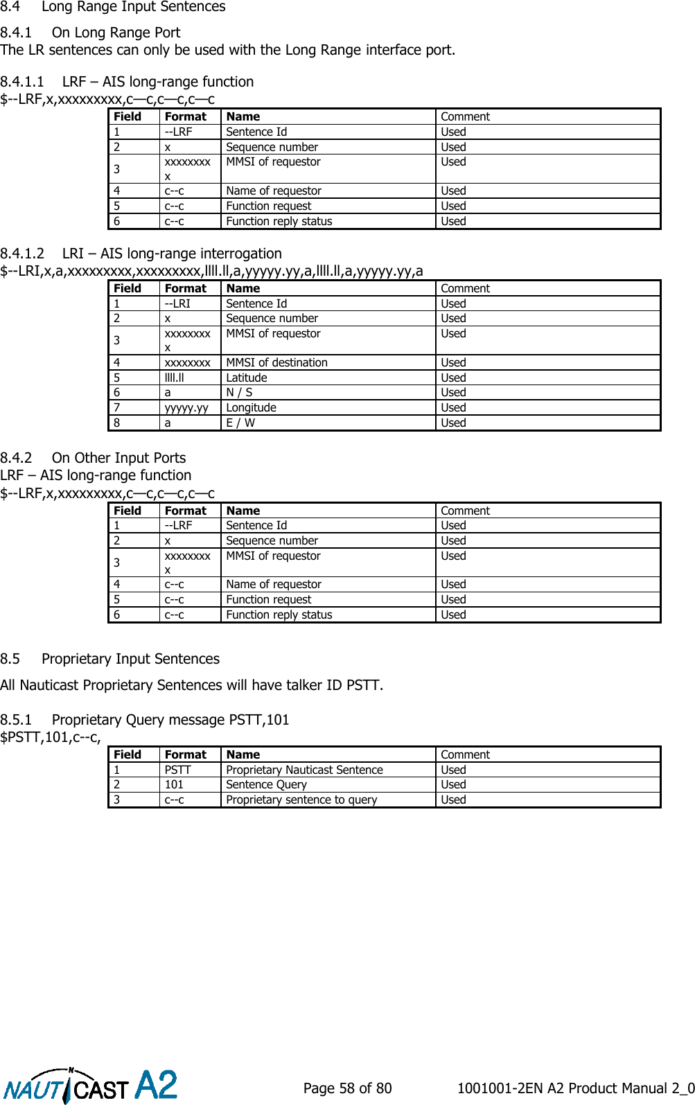
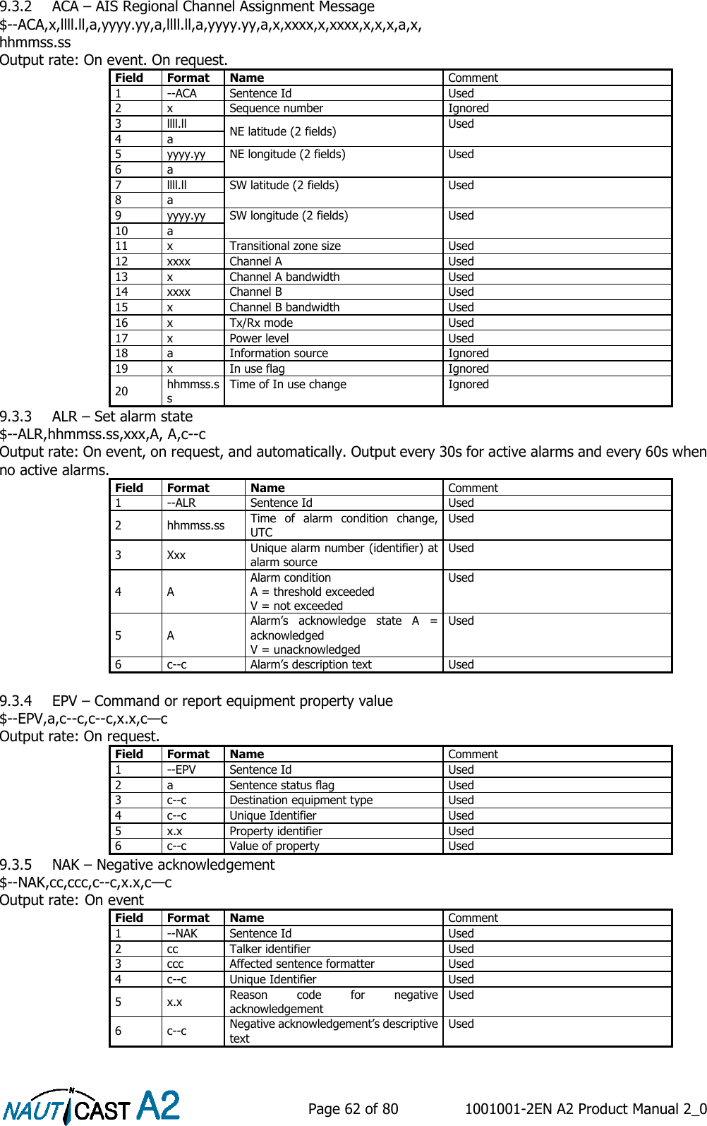
![Page 24 of 80 1001001-2EN A2 Product Manual 2_0 4.4.2 Main Menu Operational Mode Parameter Name Description Tx Mode This parameter determines the transmission of the NAUTICAST A2. If set to “Silent”, the NAUTICAST A2 will be completely silent on the VHF radio and it will not answer on interrogations. If a silent switch is used, this parameter will be locked and “Silent Switch Used” will be displayed as parameter value. 4.4.3 Main Menu Config Ship Static Parameter Name Description MMSI Maritime Mobile Service Identity reported by own ship IMO International Maritime Organization number reported by own ship Ship Name Ship name reported by own ship Call Sign Call sign reported by own ship. Shall be set to ATIS code for Inland vessel installations. Height over Keel Height over keel in meters (one decimal precision). Height over Keel information is sent as a response to an “Extended Ship Static and Voyage Related Data” request message. Ship Type (IMO) Type of Ship according to ITU-R M.1371-4. Both numerical input and selection from list is possible. ENI Unique European Vessel Identification Number reported by own ship ERI Ship Type Ship or combination type according to numeric ERI classification. Both numerical input and selection from list is possible. See chapter 10.1 “Inland ERI Ship Types” for available types. Quality Speed Shall be set to low if no type approved speed sensor is connected to transponder Quality Course Shall be set to low if no type approved course sensor is connected to transponder Quality HDG Shall be set to low if no type approved heading sensor is connected to transponder 4.4.4 Main Menu Config Ship Dimensions The parameters in the Ship Dimensions view depends on the configuration parameter “Ship Size Mode” in the Misc Interfaces view. The Ship Size Mode parameter can be set to either Standard or Simplified (default). The Ship Size Mode affects how the user should input ship size and antenna position information and how it is interpreted. Standard Mode In this mode the user must input: Convoy/ship length [m] (one decimal precision) Convoy/ship beam [m] (one decimal precision) A, B, C, D for internal antenna [m] A, B, C, D for external antenna [m] It is the users responsibility to input correctly rounded data (A+B = Convoy/ship length rounded up, C+D = Convoy/ship beam rounded up). If the user inputs data which is not correctly rounded the “Ship size mismatch” alarm will be activated. The output on the AIS data link will be exactly the values input by the user. Simplified Mode (default) In this mode the user inputs: Ship length [m] (one decimal precision) Ship beam [m] (one decimal precision) X, Y for internal antenna relative to ship [m] (one decimal precision) X, Y for external antenna relative to ship [m] (one decimal precision)](https://usermanual.wiki/Nauticast/NAUTICASTA2/User-Guide-2591154-Page-24.png)
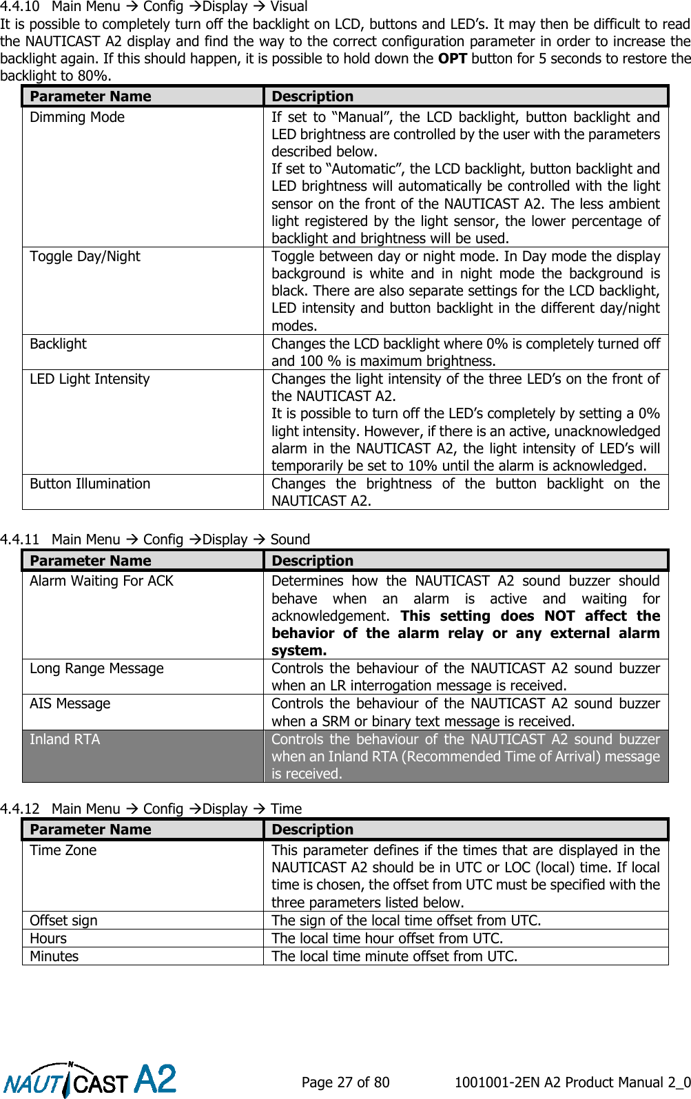
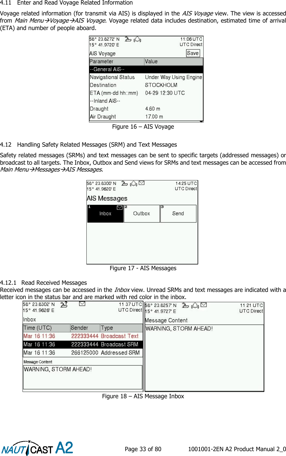
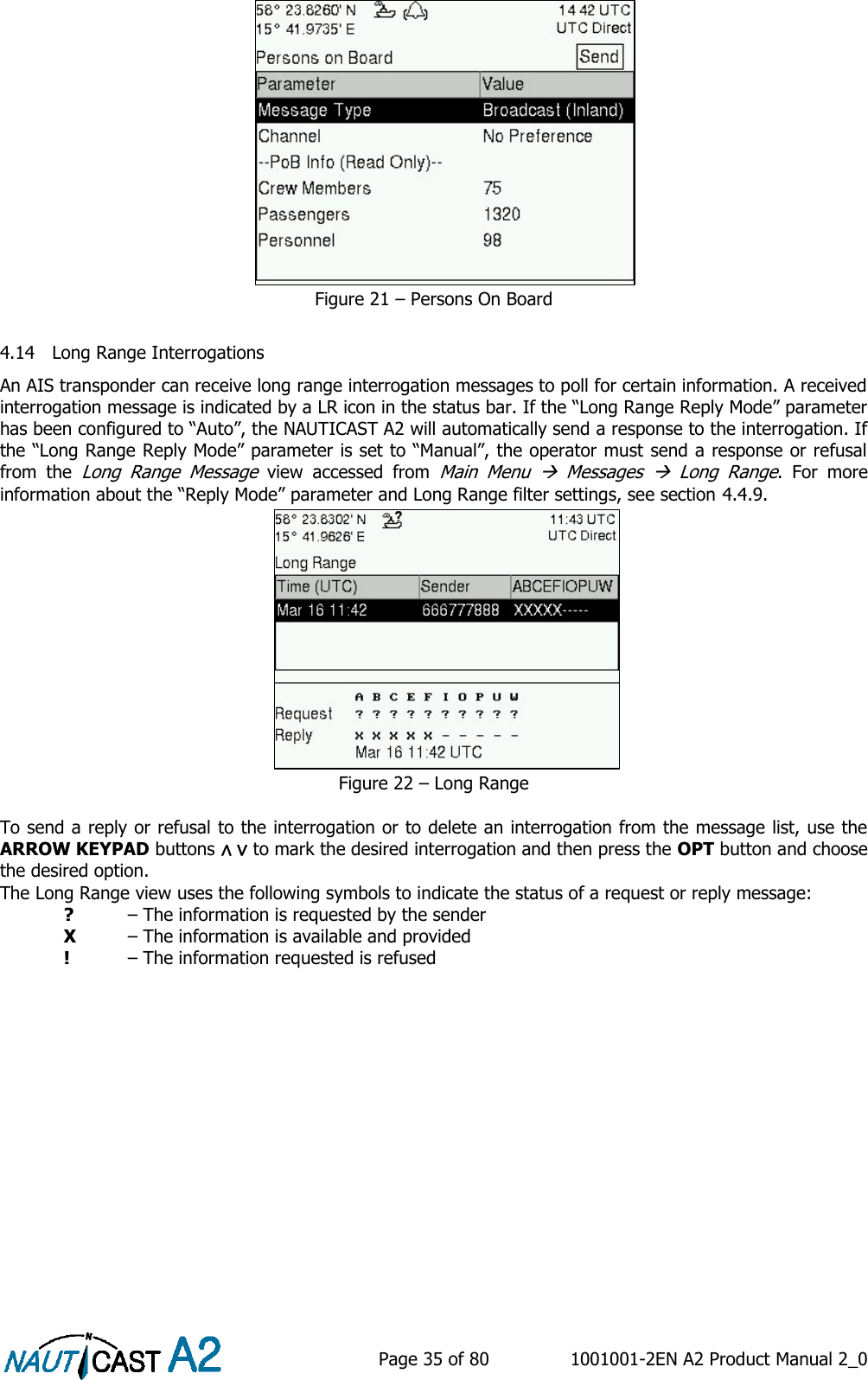
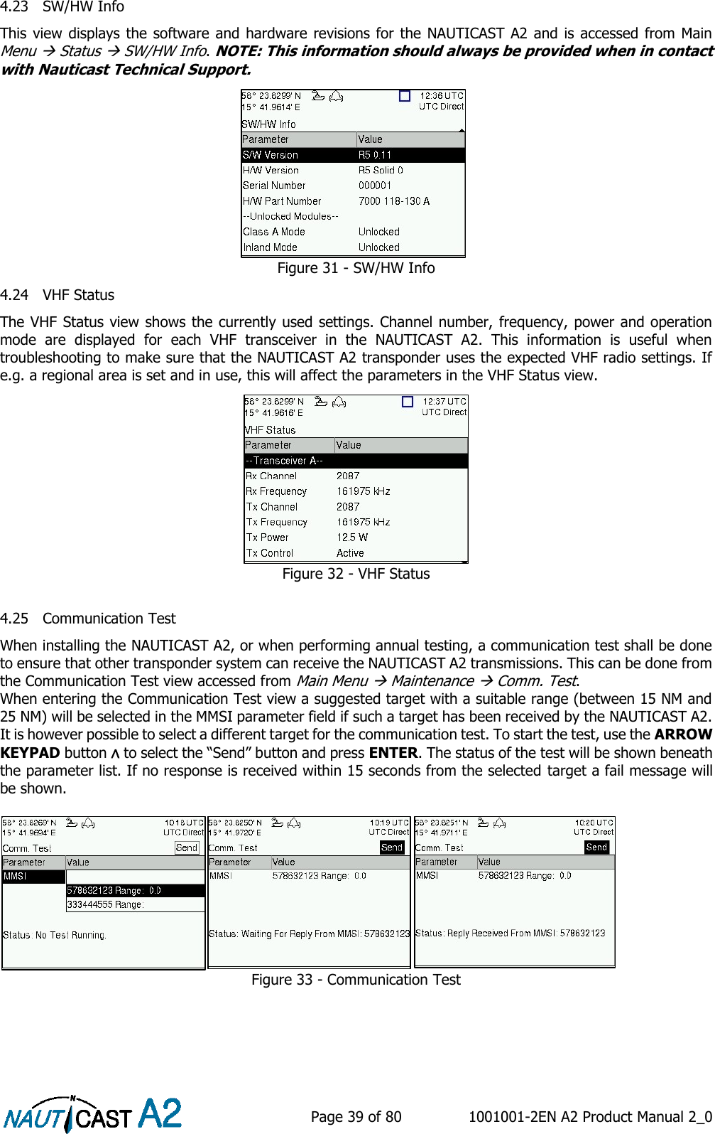
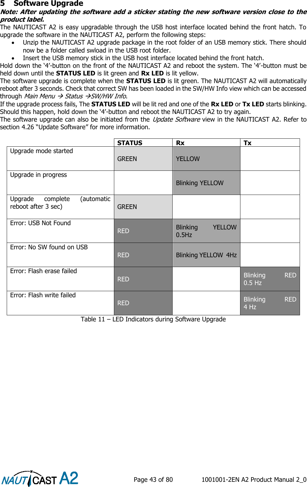
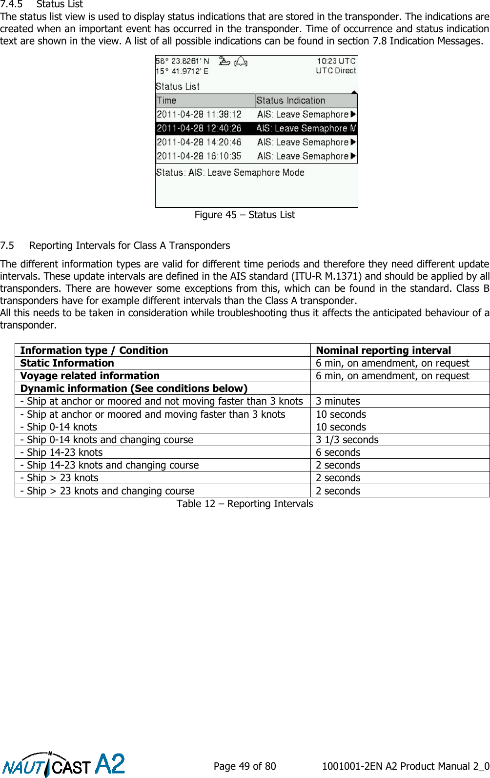
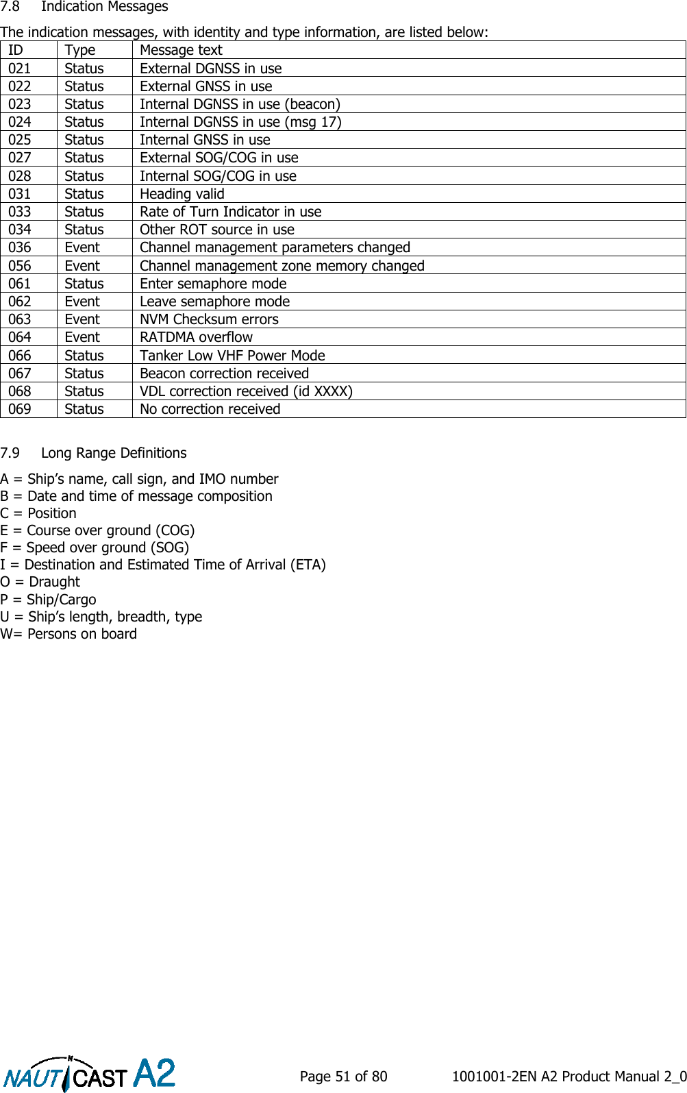
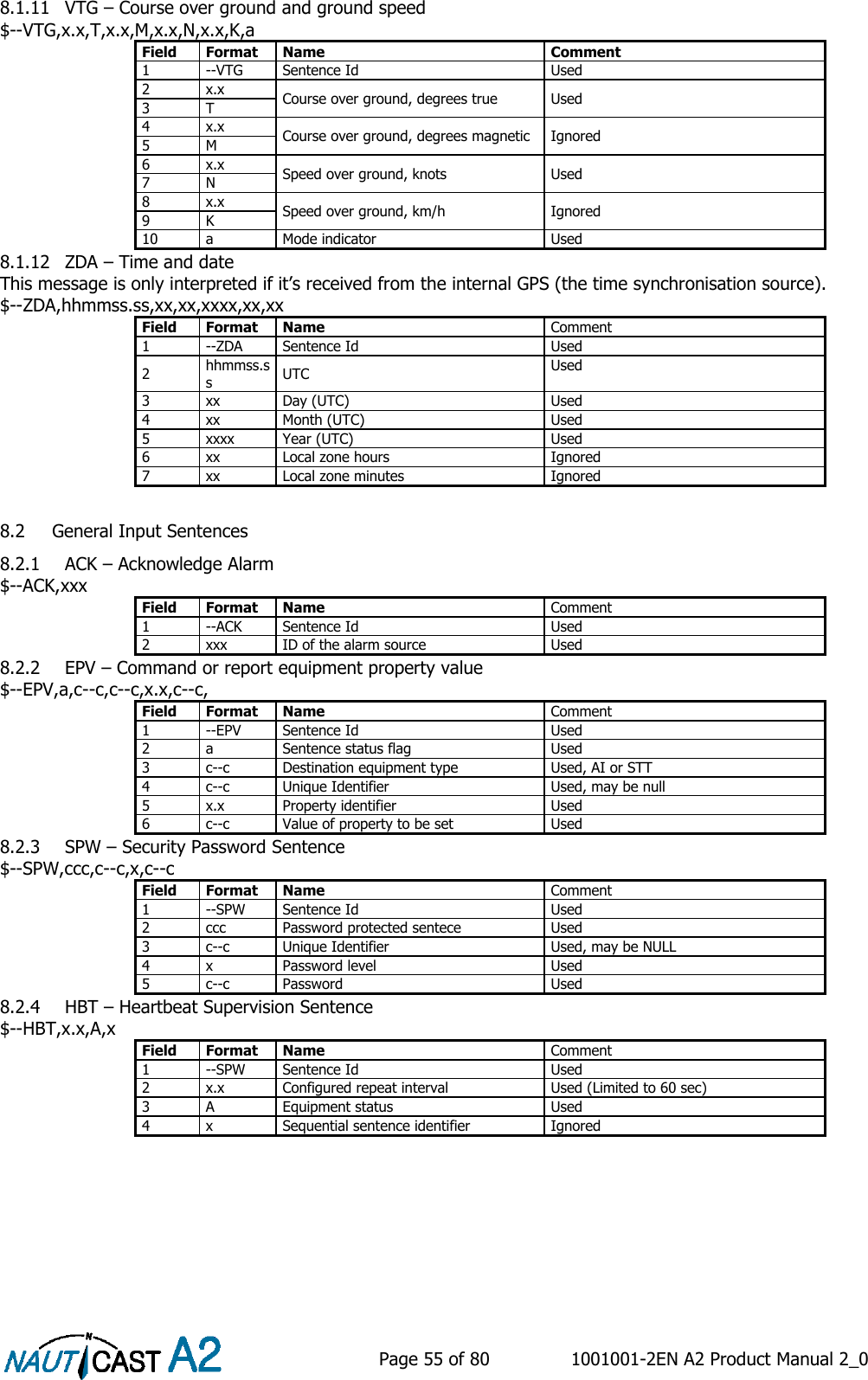
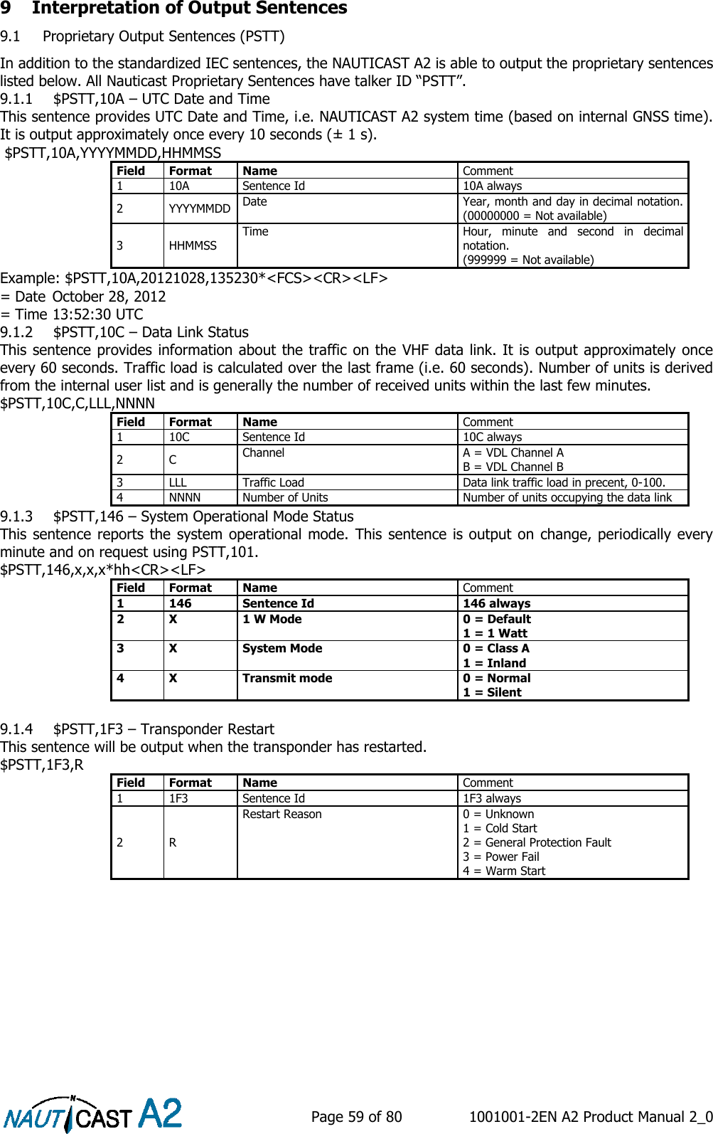
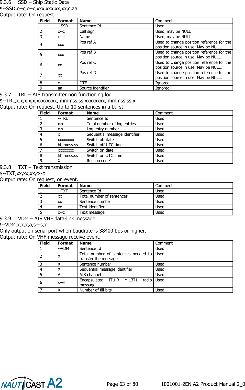
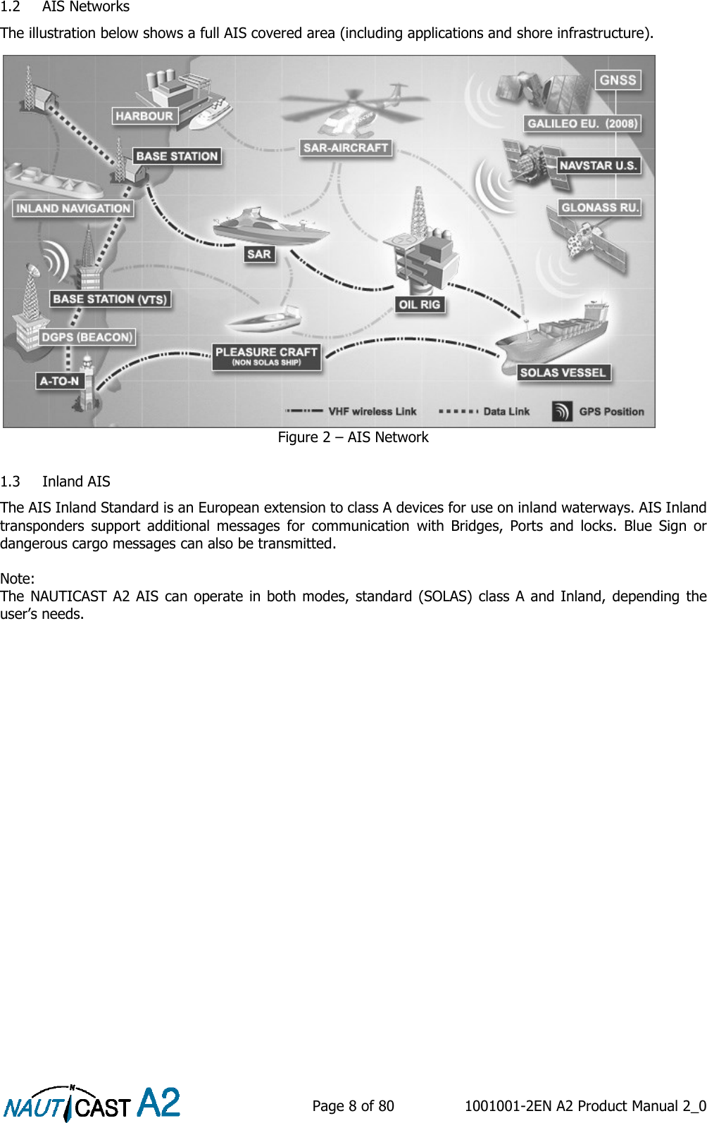
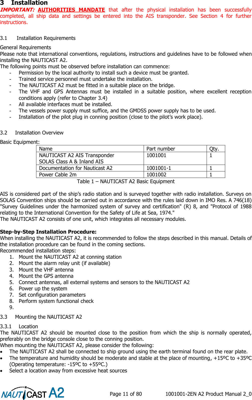
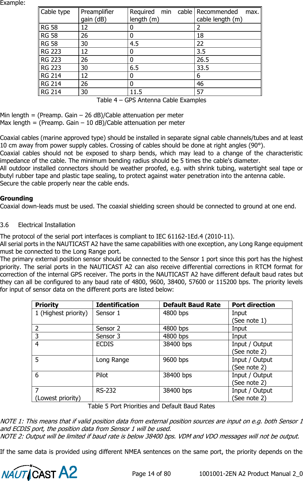
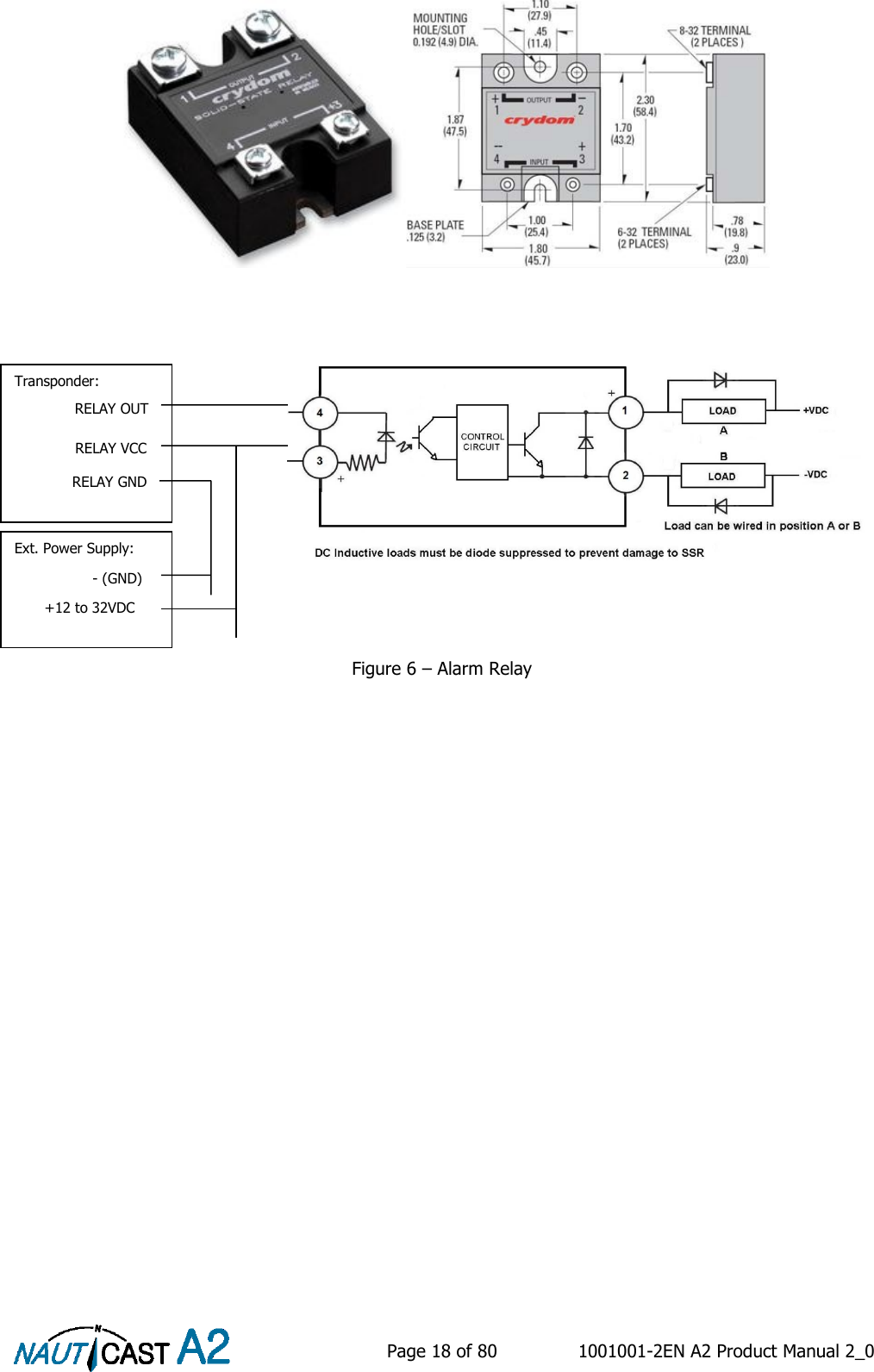
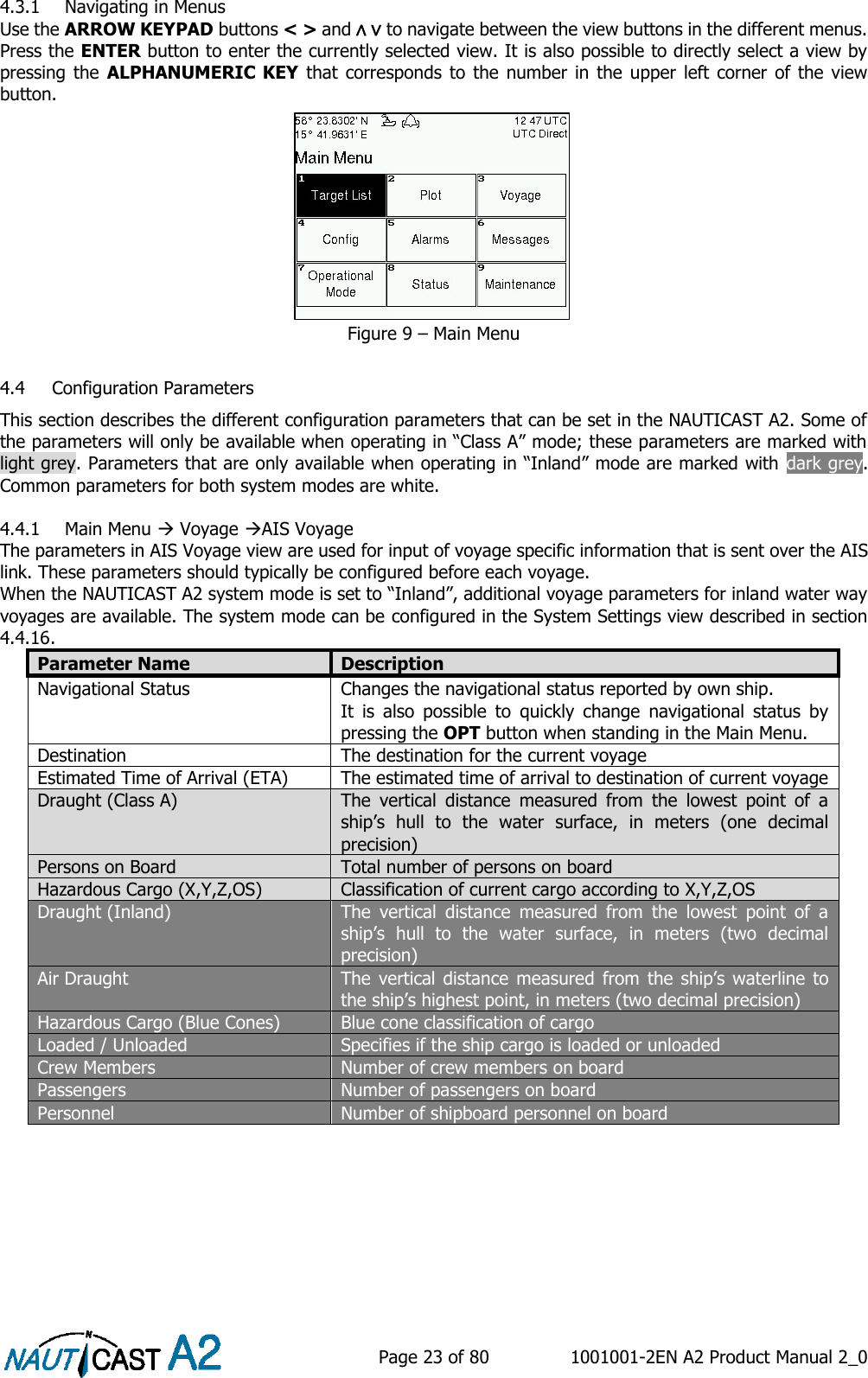
![Page 25 of 80 1001001-2EN A2 Product Manual 2_0 When operating in Inland Mode, extra convoy size can be added to ship dimension Extra convoy size on each side (value = 0 if convoy not used): Bow [m] (one decimal precision) Stern [m] (one decimal precision) Port side [m] (one decimal precision) Starboard [m] (one decimal precision) The extra convoy parameters can be configured from Main MenuVoyageConvoy Settings when the Ship Size Mode is set to “Simplified”. In this mode there is no way for the user to input mismatching data, all parameters uses the same precision and each measurement is entered only once (in standard mode it is for example possible to enter three different lengths of ship: Convoy/ship length, internal A+B and external A+B). In simplified mode the transponder will automatically calculate and correctly round the A, B, C and D values reported on the VHF link. 4.4.5 Main Menu Config VHF Radio Regional Areas This view shows the regional areas set in the transponder. To make a new regional area or to edit or delete an existing regional area, press the OPT button and choose the desired action. The following parameters can be edited when “New Area” or “Edit Area” is chosen: Parameter Name Description Channel A The channel number for AIS channel A (2087 = default) that should be used in the regional area. Channel B The channel number for AIS channel B (2088 = default) that should be used in the regional area. Zone Size The transitional zone size of the regional area in nautical miles (NM). Tx Mode Decides on which channels the transponder will use when transmitting in the regional area. When set to “Silent”, the transponder will stop automatic transmissions on AIS channels A and B. Power Output power for the transponder in the regional area. High = 12.5 W, Low = 1 W. LAT NE The latitude for the North East corner of the regional area LON NE The longitude for the North East corner of the regional area LAT SW The latitude for the South West corner of the regional area LON SW The longitude for the South West corner of the regional area 4.4.6 Main Menu Config VHF Radio LR Broadcast Settings Parameter Name Description LR Broadcast Ch. 1 The first channel number for broadcasting long range message 27. The message is sent every 6 minutes on each channel so if both channels are configured a message 27 will be broadcasted every 3 minutes. If this parameter is set to zero no long range broadcast transmissions will be sent on this channel. LR Broadcast Ch. 2 The second channel number for broadcasting long range message 27. The message is sent every 6 minutes on each channel so if both channels are configured a message 27 will be broadcasted every 3 minutes. If this parameter is set to zero no long range broadcast transmissions will be sent on this channel. 4.4.7 Main Menu Config Alarm In this view all alarms can be configured to either “Enabled” or “Disabled”. When the alarm is enabled, an active alarm will affect the external alarm relay, the buzzer in the NAUTICAST A2 and show a popup dialog in the display. When the alarm is set to disabled it will not affect anything when the alarm becomes active. For more information about the alarm view, refer to section 4.18 “Alarms”. For a list of all the alarms that can occur, refer to section 7.3 “Troubleshooting with Alarm Messages.”](https://usermanual.wiki/Nauticast/NAUTICASTA2/User-Guide-2591154-Page-25.png)