Nauticast NAUTICASTA2 NAUTICAST A2 User Manual
Nauticast GmbH NAUTICAST A2 Users Manual
Users Manual
PRODUCT MANUAL
Class-A SOLAS/Inland
AIS Transponder
Art. No. 100 1001
Nauticast GmbH
Lützowgasse 12-14 / 3.OG
1140 Vienna, Austria
T: +43 (1) 5 237 237-0
F: +43 (1) 5 237 237-150
office@nauticast.com

Page 2 of 80 1001001-2EN A2 Product Manual 2_0
DISCLAIMER
Although Nauticast GmbH strives for accuracy in all its publications this material may contain errors or omissions and is
subject to change without prior notice. Nauticast GmbH shall not be made liable for any specific, indirect, incidental or
consequential damages as a result of the usage of this manual. Please visit our website for the latest manual revision at
www.nauticast.com if necessary.
COPYRIGHT PROTECTION
This document is protected by copyright law. Copying or duplicating be it physically or electronically for any usage other
than the operation of a Nauticast A2 AIS System is prohibited and any offender may be liable to the payment of damages.
Dieses Dokument ist urheberrechtlich geschützt. Jede Weitergabe oder Vervielfältigung dieser Unterlage ist ausschließlich
zur Unterstützung des Betriebes eines Nauticast A2 AIS Systems zulässig. Zuwiderhandlungen verpflichten zu
Schadenersatz.
Ce document est protégé par le droit d'auteur. Toute redistribution ou reproduction de ce document est autorisée
exclusivement pour appuyer le fonctionnement d'un système AIS A2 Nauticast. Les contrevenants seront passibles de
dommages-intérêts.
Este documento está protegido por derechos de autor. Cualquier redistribución o reproducción de este documento está
permitida exclusivamente para apoyar la operación de un sistema AIS A2 Nauticast. Los infractores quedan obligados por
daños y perjuicios.
GENERAL WARNINGS
All marine Automatic Identification System (AIS) units utilize a satellite based system such as the Global Positioning Satellite
(GPS) network or the Global Navigation Satellite System (GLONASS) network to determine their position. The accuracy of
these networks is variable and is affected by factors such as the antenna positioning, the number of satellites that are
available to determine a position and how long satellite information has been received for. It is desirable wherever possible
to verify both your vessel’s AIS derived position data and other vessels’ AIS derived position data with visual or radar
based observations.
In most countries the operation of an AIS unit is included under the vessel’s marine VHF license provisions. The vessel
onto which the AIS unit is to be installed must therefore possess a valid VHF radiotelephone license which lists the AIS
system and the vessel Call Sign and MMSI number. Please contact the relevant authority in your country for more
information.
LIMITED WARRANTY
This product is warranted against factory defect in material and workmanship for a period of 24 months from the date of
purchase. During the warranty period Nauticast GmbH will repair or at its option, replace the product at no cost to the
buyer provided that a return authorization is obtained from Nauticast GmbH, Lützowgasse 12-14 / 3. OG, 1140 Vienna,
Austria (see Section Contact & Support information). This warranty does not apply if the product has been damaged by
accident or misuse, or as a result of service or modification by unauthorized service personnel. For authorized service
partners see our homepage www.nauticast.com or contact Nauticast support directly.
Warranty and certification void if device is opened.
© 2014 Nauticast GmbH
Nauticast™ is a protected trademark of Nauticast GmbH

Page 3 of 80 1001001-2EN A2 Product Manual 2_0
Index
1 GENERAL INTRODUCTION ...................................................................................................................... 6
1.1 Description of AIS..................................................................................................................... 6
1.2 AIS Networks ........................................................................................................................... 8
1.3 Inland AIS................................................................................................................................ 8
2 SYSTEM OVERVIEW .............................................................................................................................. 9
2.1 Product Description .................................................................................................................. 9
2.2 Main features ......................................................................................................................... 10
3 INSTALLATION .................................................................................................................................. 11
3.1 Installation Requirements ....................................................................................................... 11
3.2 Installation Overview .............................................................................................................. 11
3.3 Mounting the NAUTICAST A2 .................................................................................................. 11
3.4 Mount the NAUTICAST A2 VHF antenna ................................................................................... 12
3.5 Mount the NAUTICAST A2 GPS Antenna .................................................................................. 13
3.6 Electrical Installation ............................................................................................................... 14
3.7 System Configuration .............................................................................................................. 19
4 OPERATION...................................................................................................................................... 20
4.1 System Mode ......................................................................................................................... 20
4.2 LED’s and Controls ................................................................................................................. 20
4.3 Main Menu – Tree View .......................................................................................................... 22
4.4 Configuration Parameters ........................................................................................................ 23
4.5 Alarm and Alert Pop-ups ......................................................................................................... 29
4.6 Status Bar .............................................................................................................................. 30
4.7 Status Icons ........................................................................................................................... 30
4.8 View Remote Ship Information ................................................................................................ 31
4.9 View Plot of Targets ............................................................................................................... 32
4.10 View Transmitted Own Ship Information .................................................................................. 32
4.11 Enter and Read Voyage Related Information ............................................................................ 33
4.12 Handling Safety Related Messages (SRM) and Text Messages ................................................... 33
4.13 Send Persons On Board .......................................................................................................... 34
4.14 Long Range Interrogations ...................................................................................................... 35
4.15 Inland ETA and RTA ............................................................................................................... 36
4.16 Inland Water Levels ................................................................................................................ 36
4.17 Regional Areas ....................................................................................................................... 37
4.18 Alarms ................................................................................................................................... 37
4.19 Status List .............................................................................................................................. 37
4.20 Non Functional Time ............................................................................................................... 38
4.21 GPS Status ............................................................................................................................. 38
4.22 View Raw Data ....................................................................................................................... 38
4.23 SW/HW Info ........................................................................................................................... 39
4.24 VHF Status ............................................................................................................................. 39
4.25 Communication Test ............................................................................................................... 39
4.26 Update Software .................................................................................................................... 40
4.27 Restore Config ....................................................................................................................... 40
4.28 Save Configuration to USB memory ......................................................................................... 40
4.29 Load Configuration from USB memory ..................................................................................... 41
5 SOFTWARE UPGRADE .......................................................................................................................... 43
6 TECHNICAL SPECIFICATIONS ................................................................................................................. 44
6.1 Transponder Physical .............................................................................................................. 44
6.2 Transponder Electrical ............................................................................................................ 44
6.3 Transponder Environment ....................................................................................................... 44
6.4 Transponder VHF Transceiver ................................................................................................. 44
6.5 Transponder Internal GPS Receiver ......................................................................................... 44
6.6 AIS Alarm Relay ..................................................................................................................... 44
7 TROUBLESHOOTING............................................................................................................................ 45
7.1 Troubleshooting Prerequisites ................................................................................................. 45
7.2 Troubleshooting with the Front Panel LED’s ............................................................................. 45
7.3 Troubleshooting with Alarm Messages ..................................................................................... 45
7.4 Troubleshooting via the Display ............................................................................................... 47
7.5 Reporting Intervals for Class A Transponders ........................................................................... 49

Page 4 of 80 1001001-2EN A2 Product Manual 2_0
7.6 F.A.Q ..................................................................................................................................... 50
7.7 Contact & Support information ................................................................................................ 50
7.8 Indication Messages ............................................................................................................... 51
7.9 Long Range Definitions ........................................................................................................... 51
8 INTERPRETATION OF INPUT SENTENCES .................................................................................................. 52
8.1 GPS and Sensor Input Sentences ............................................................................................. 52
8.2 General Input Sentences ......................................................................................................... 55
8.3 AIS Specific Input Sentences ................................................................................................... 56
8.4 Long Range Input Sentences .................................................................................................. 58
8.5 Proprietary Input Sentences .................................................................................................... 58
9 INTERPRETATION OF OUTPUT SENTENCES ................................................................................................ 59
9.1 Proprietary Output Sentences (PSTT) ...................................................................................... 59
9.2 Long Range Output Sentences ................................................................................................ 60
9.3 AIS Output Sentences ............................................................................................................. 61
10 GLOSSARY ....................................................................................................................................... 65
10.1 Inland ERI Ship Types ............................................................................................................ 67
10.2 Units ...................................................................................................................................... 68
11 APPENDIX ........................................................................................................................................ 69
11.1 Appendix A – Drawings ........................................................................................................... 69
11.2 Appendix B – License .............................................................................................................. 72
11.3 Appendix C – Declaration of Conformity ................................................................................... 75
11.4 Appendix D – Certification ....................................................................................................... 76

Page 5 of 80 1001001-2EN A2 Product Manual 2_0
History of Changes
Software dependencies
This revision of the Manual is valid for the Software version (s) below stated and future versions unless
otherwise noted. Please find further information on the Nauticast homepage (www.nauticast.com).
Current software version can always be verified in the S/W info dialog as described in section 4.23.
Safety Instructions
Note the following compass safe distances:
Disposal Instructions
Broken or unwanted electrical or electronic equipment parts shall be classified and handled as ‘Electronic
Waste’. Improper disposal may be harmful to the environment and human health. Please refer to your local
waste authority for information on return and collection systems in your area.
Contact Information
For installation, service, ordering info and technical support please contact your local Nauticast service partner.
A list of dealers and service stations can be found on our website http://www.nauticast.com.
Date
Version
Status
Comments
Responsible
2013-07-15
1.2
Release
First Official Release
Ch. Aschl
2014-01-28
1.3
Release
Changes due to SW update
Ch. Aschl
2014-09-30
2.0
Release
Nauticast, Certification, general rework
V. Janik
Date
AIS software Version
Status
Comments
Responsible
2014-07-01
1.1.10
Release
Type approved
V. Janik
Equipment
Standard magnetic compass
Steering magnetic compass
Nauticast A2 Transponder
0.60 m
0.45 m

Page 6 of 80 1001001-2EN A2 Product Manual 2_0
1 General Introduction
1.1 Description of AIS
AIS stands for: “Automatic Identification System”
What is AIS?
According to IALA regulations, AIS is defined as follows:
AIS is a broadcast transponder system, operating in the VHF maritime mobile Band (161,975 and 162,025
MHz). It is capable of sending ship information such as identification, position, course, speed and more to
other ships and to shore stations. It can handle multiple reports at rapid update rates and uses Self-Organizing
Time Division Multiple Access (SOTDMA) technology to meet these high broadcast rates and ensure reliable
and robust operation.
The Modules of an AIS are:
DGPS / GPS receiver
VHF Radio
Antenna
Computer (CPU)
Power Supply
Appropriate application software connects the individual modules.
In which modes do AIS operate?
AIS devices are required to function flawlessly in a variety of modes. The relevant regulations require that the
system shall be capable of
An "autonomous and continuous" mode for operation in all areas. This mode shall be capable of being
switched to/from one of the following alternate modes by a competent authority;
An "assigned" mode for operation in an area subject to a competent authority responsible for traffic
monitoring such that the data transmission interval and/or time slots may be set remotely by that
authority;
A "polling or controlled" mode, where the data transfer occurs in response to interrogation from a ship
or competent authority.
Types of AIS:
Class A Transponder – This type of transponder is used on open sea waters and is mandatory for ships
of 300 gross tonnage or more on international voyages, all cargo ships of 500 gross tonnage or more
and on passenger ships.
Class B Transponder – Used on smaller vessels and pleasure crafts. It transmits with less power than
class A transponders and has a lower priority ranking on the data link.
Base Station – Fixed shore station that is typically connected to an AIS network to collect information
from all vessels around a certain port or shore line.
Repeater Stations – Used to extend the coverage range by repeating incoming messages. Can be
implemented as a function in an AIS Base station or an AtoN station.
SAR (Search and Rescue) Transponder – Used on airplanes and helicopters in search and rescue
missions.
AtoN (Aids to Navigation) – A transceiver that is fitted on buoys and lighthouses in order to send
information about their positions.
Inland AIS – A European standardized extension to Class A systems for use on inland water ways. An
inland transponder has additional messages to communicate with bridges, ports and locks and can
also send some additional information that are useful on water ways such as blue sign indication,
specific hazardous cargo etc.
SART (Search and Rescue Transmitters) – Distress beacons for life rafts. An active SART signal will
always be sorted at the top of the target list to highlight its presence.
Page 7 of 80 1001001-2EN A2 Product Manual 2_0
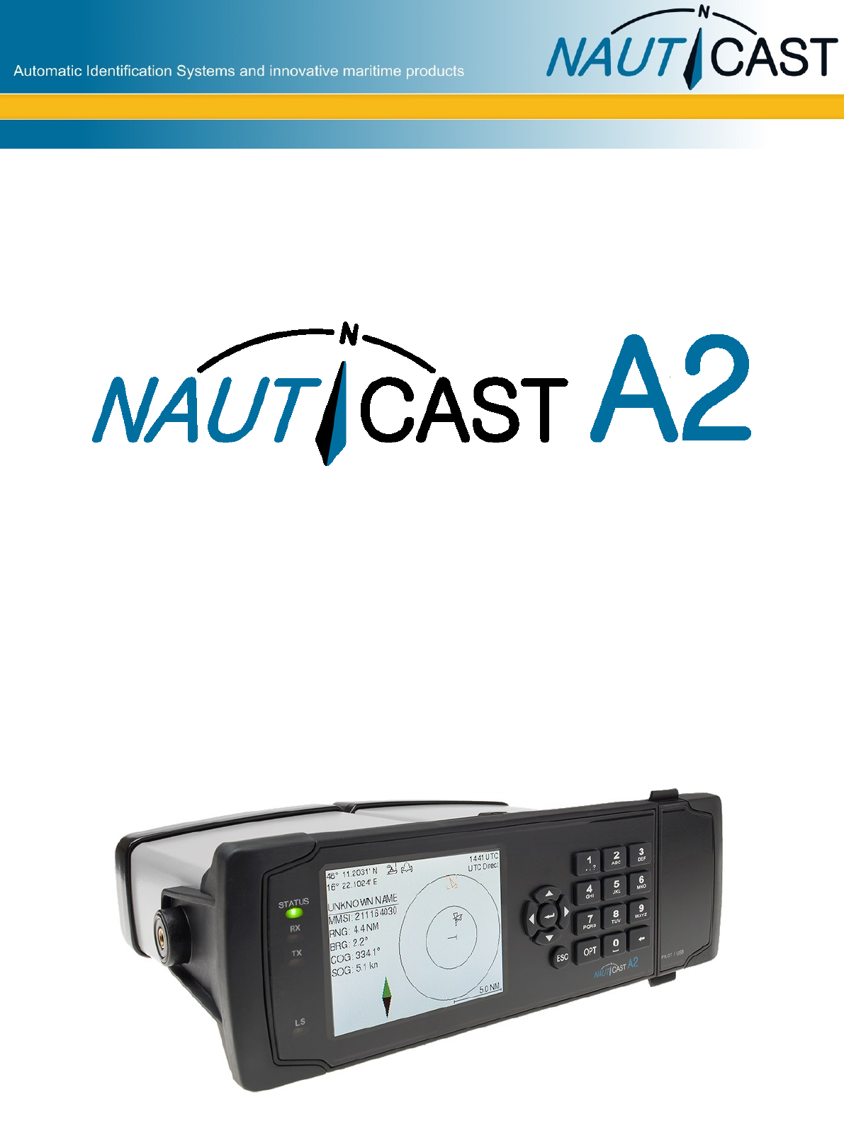
AIS in an Operational Environment
This illustration depicts a typical AIS System, where two or more AIS equipped vessels (and
shore based systems) are automatically communicating with each other.
Figure 1 – AIS System
Both vessels in the above illustration are equipped with a NAUTICAST A2 (or any other certified AIS-
Transponder). Due to “Time – Synchronization” they use the same organization of free and allocated
windows (Slots) in the shared VHF Data Link (this method is called “Self Organized Time Division Multiple
Access”) to send and receive messages.
On the next page, a typical NAUTICAST A2 installation in a common environment is shown. The NAUTICAST
A2 is connected to the vessel’s emergency power supply, and in connection with the VHF, and GPS-
Antennas, the minimal requirements for transponder operation are fulfilled. By means of standardized
messages the involved AIS systems exchange certain static data and dynamic information, such as the
location and the course of the other ships in the area.

Page 8 of 80 1001001-2EN A2 Product Manual 2_0
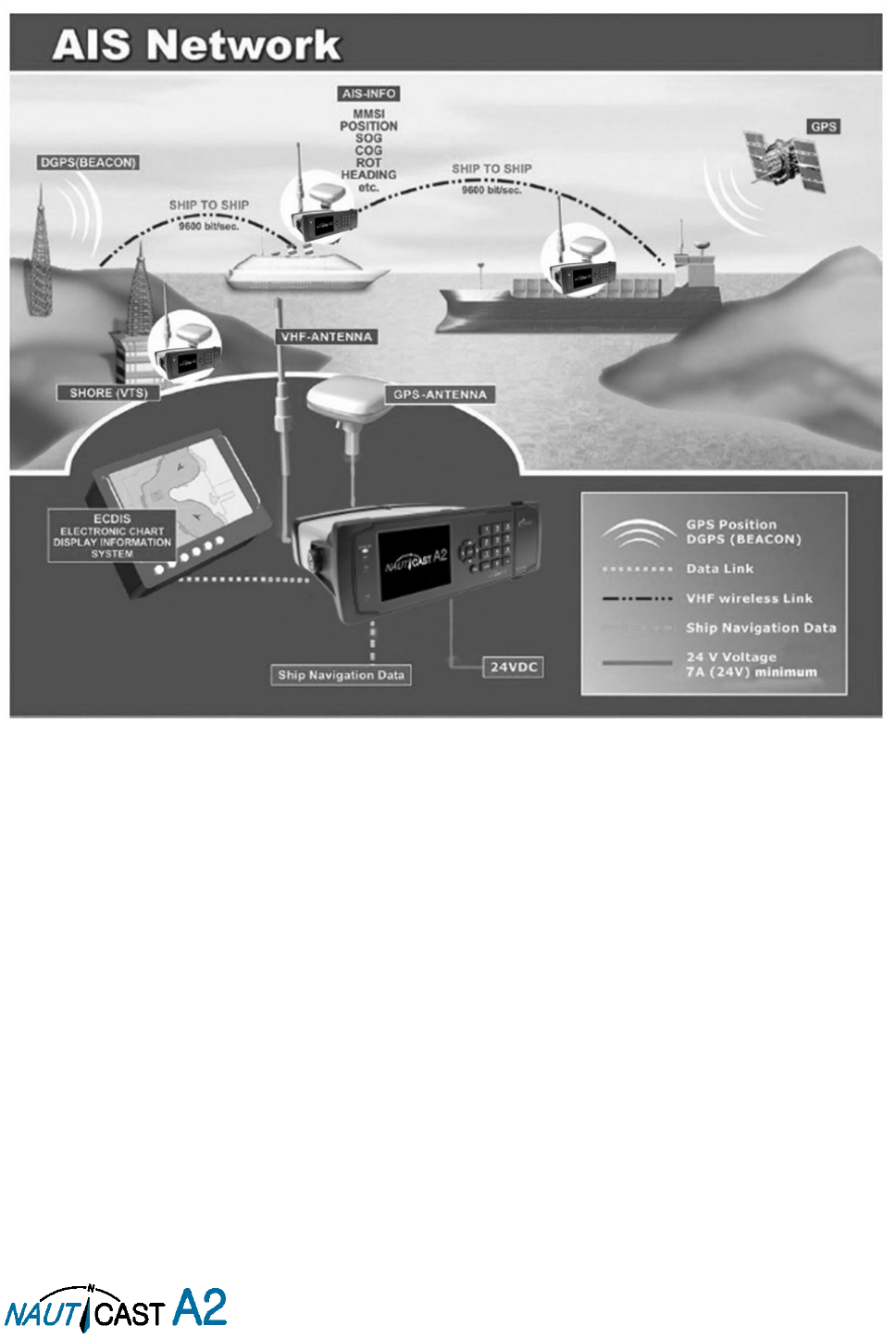
1.2 AIS Networks
The illustration below shows a full AIS covered area (including applications and shore infrastructure).
Figure 2 – AIS Network
1.3 Inland AIS
The AIS Inland Standard is an European extension to class A devices for use on inland waterways. AIS Inland
transponders support additional messages for communication with Bridges, Ports and locks. Blue Sign or
dangerous cargo messages can also be transmitted.
Note:
The NAUTICAST A2 AIS can operate in both modes, standard (SOLAS) class A and Inland, depending the
user’s needs.
Page 9 of 80 1001001-2EN A2 Product Manual 2_0
2 System Overview
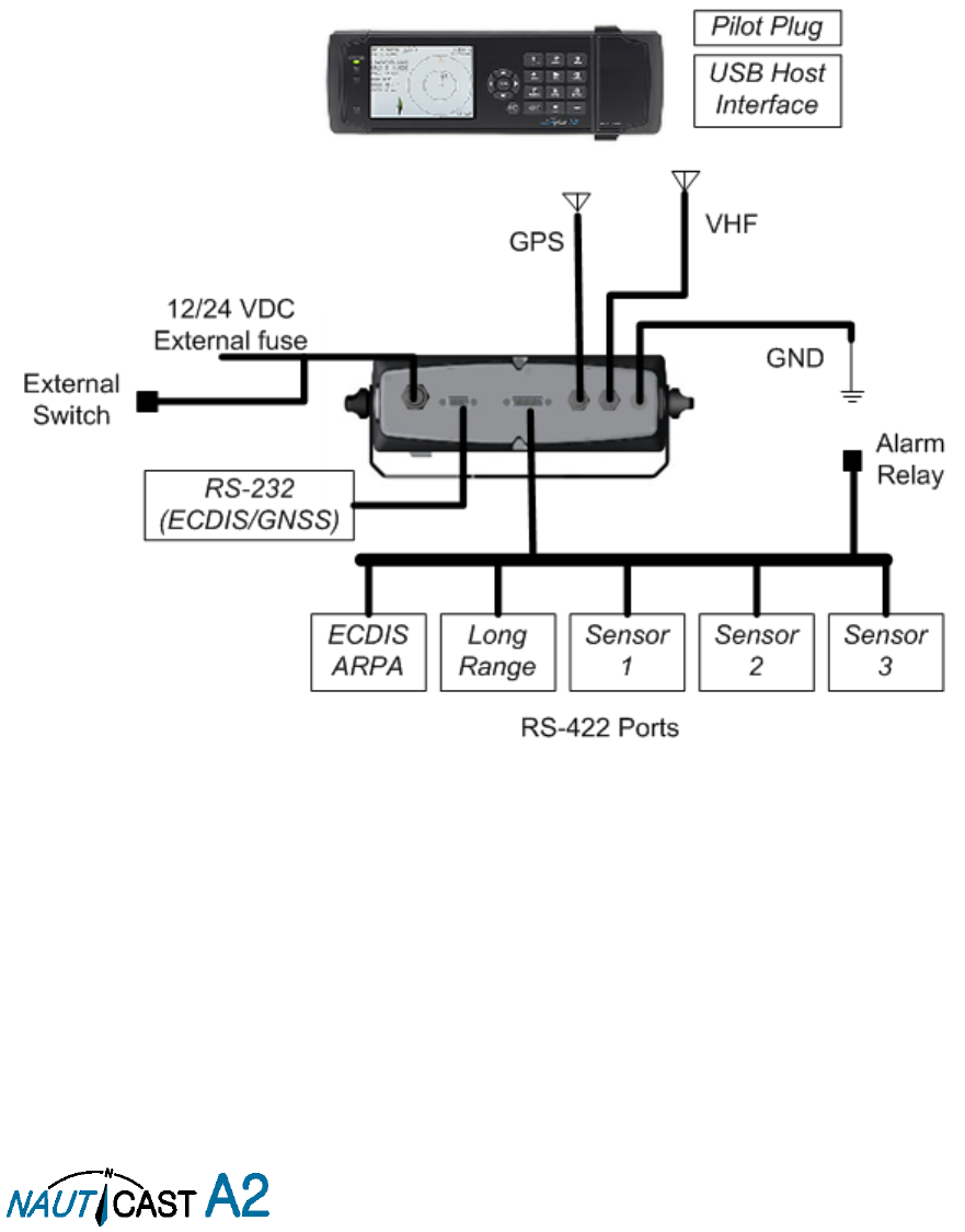
2.1 Product Description
The NAUTICAST A2 System consists of a transceiver radio unit, a GPS receiver, a controller unit and a colour
LCD with a numerical keypad. The radio has three receivers, two tuneable TDMA receivers and one DSC
receiver. The transmitter alternates its transmissions between the two operating TDMA. The controller unit
creates and schedules data packets (containing dynamic, static and voyage related data) for transmission
based on the IMO performance standard for AIS.
The NAUTICAST A2 shall be connected to the ship’s sensors as required by the installation guidelines published
by IALA. The NAUTICAST A2 can interface external navigation and presentation systems that support required
IEC 61162-1 sentences
.
Refer to chapter 8 for more information. The NAUTICAST A2 is prepared for connection
to Long Range systems like Inmarsat C.
The colour LCD and numerical keypad provides a graphical user-friendly interface to the system. It is possible
to plot the location of other vessels, aids to navigation and search and rescue vessels. The LCD and numerical
keypad can also be used to send and receive messages, perform configuration as well as supervise the systems
status.
Figure 3 – System Overview

Page 10 of 80 1001001-2EN A2 Product Manual 2_0
2.2 Main features
Multi-colour 3.5” LCD with numerical keypad interface.
USB Host interface for connection of USB keyboard and USB flash memories.
Individual visual display settings for day and night operations.
Broadcast of Dynamic, Static and Voyage related information.
Standardized interface for connection to ship sensors e.g. GNSS, Gyro, Rate of Turn Indicator,
ECDIS/ECS and ARPA.
Plot capable of presenting up to 500 targets in the vicinity of the own ship.
Messaging views for generation and presentation of safety related messages and text messages.
Pilot plug integrated to the front of the transponder unit.
Channel management capability for areas without access to the worldwide allocated AIS frequencies.
Possibility to generate Long Range AIS reply over satcom equipment such as Inmarsat C.
In addition to the normal high (12,5W) and low (1W) power mode, the NAUTICAST A2 has a 1W
tanker mode in accordance with requirements for tanker operations in port.
Reception and processing of AIS messages 18,19 and 24A/B as transmitted by AIS Class B ‘CS’
Transponders.
Easily upgraded with the latest software release from Nauticast using USB memory.
Save/Restore configuration using USB Storage.

Page 11 of 80 1001001-2EN A2 Product Manual 2_0
3 Installation
IMPORTANT:
AUTHORITIES MANDATE that after the physical installation has been successfully
completed, all ship data and settings be entered into the AIS transponder. See Section 4 for further
instructions.
3.1 Installation Requirements
General Requirements
Please note that international conventions, regulations, instructions and guidelines have to be followed when
installing the NAUTICAST A2.
The following points must be observed before installation can commence:
- Permission by the local authority to install such a device must be granted.
- Trained service personnel must undertake the installation.
- The NAUTICAST A2 must be fitted in a suitable place on the bridge.
- The VHF and GPS Antennas must be installed in a suitable position, where excellent reception
conditions apply (refer to Chapter 3.4)
- All available interfaces must be installed.
- The vessels power supply must suffice, and the GMDSS power supply has to be used.
- Installation of the pilot plug in conning position (close to the pilot’s work place).
3.2 Installation Overview
Basic Equipment:
Name
Part number
Qty.
NAUTICAST A2 AIS Transponder
SOLAS Class A & Inland AIS
1001001
1
Documentation for Nauticast A2
1001001-1
1
Power Cable 2m
1001002
1
Table 1 – NAUTICAST A2 Basic Equipment
AIS is considered part of the ship’s radio station and is surveyed together with radio installation. Surveys on
SOLAS Convention ships should be carried out in accordance with the rules laid down in IMO Res. A 746(18)
"Survey Guidelines under the harmonized system of survey and certification" (R) 8, and "Protocol of 1988
relating to the International Convention for the Safety of Life at Sea, 1974."
The NAUTICAST A2 consists of one unit, which integrates all necessary modules.
Step-by-Step Installation Procedure:
When installing the NAUTICAST A2, it is recommended to follow the steps described in this manual. Details of
the installation procedure can be found in the coming sections.
Recommended installation steps:
1. Mount the NAUTICAST A2 at conning station
2. Mount the alarm relay unit (if available)
3. Mount the VHF antenna
4. Mount the GPS antenna
5. Connect antennas, all external systems and sensors to the NAUTICAST A2
6. Power up the system
7. Set configuration parameters
8. Perform system functional check
9.
3.3 Mounting the NAUTICAST A2
3.3.1 Location
The NAUTICAST A2 should be mounted close to the position from which the ship is normally operated,
preferably on the bridge console close to the conning position.
When mounting the NAUTICAST A2, please consider the following:
The NAUTICAST A2 shall be connected to ship ground using the earth terminal found on the rear plate.
The temperature and humidity should be moderate and stable at the place of mounting, +15ºC to +35ºC
(Operating temperature: -15ºC to +55ºC.)
Select a location away from excessive heat sources
Page 12 of 80 1001001-2EN A2 Product Manual 2_0
Ensure that there is enough airflow to avoid high ambient temperatures
Avoid areas where there is a high flow of humid salt air
Avoid places with high levels of vibrations and shocks
Avoid mounting the NAUTICAST A2 in direct sunlight for the best readability
Ensure that the cables can be connected without violating their minimum bending radius
The unit can affect magnetic compasses. The minimum compass safe distance is 0.60 meters to a standard
magnetic compass and 0.45 meters to a steering magnetic compass
Regarding the physical size please see the Appendix A – Drawings containing all mechanical drawings.
3.4 Mount the NAUTICAST A2 VHF antenna
Interference to the Ship’s VHF Radiotelephone
The AIS ship borne equipment, like any other ship borne transceiver operating in the VHF maritime band, may
cause interference to a ship’s VHF radiotelephone. Because AIS is a digital system, this interference may occur
as a periodic (e.g. every 20 seconds) soft clicking sound on the ship’s radiotelephone. This affect may become
more noticeable if the VHF radiotelephone antenna is located close to the AIS VHF antenna, and when the
radiotelephone is operating on channels near the AIS operating channels (e.g. channels 27, 28 and 86).
Attention should be paid to the location and installation of the various antennas, in order to support the
antenna characteristics in the best possible way.
3.4.1 VHF Antenna Location
Location of the mandatory AIS VHF-antenna should be carefully considered. Digital communication is more
sensitive than analogue/voice communication to interference created by reflections caused by obstructions
such as masts and booms. It may be necessary to relocate the VHF radiotelephone antenna to minimize
interference effects.
To minimize interference effects, the following guidelines apply:
The AIS VHF antenna should have omnidirectional vertical polarization.
The AIS VHF antenna should be placed in an elevated position, as free standing as possible, with a
minimum of 2 meters in horizontal direction from constructions made of conductive materials. The antenna
should not be installed close to any large vertical obstruction. The AIS VHF antenna should have a visible
sky of 360°.
The AIS VHF antenna should be installed at least 3 meters away from interfering high-power energy
sources such as radar and other transmitting radio antennas, and out of the way of the transmitting beam.
There should not be more than one antenna on each level. The AIS VHF antenna should be mounted
directly above or below the ship’s primary VHF radiotelephone antenna, with no horizontal separation and
a minimum of 2 meters vertical separation. If it is located on the same level as other antennas, the distance
apart should measure at least 10 meters.
3.4.2 VHF Cabling
The cable should be kept as short as possible to minimize attenuation of the signal. Double shielded coaxial
cable equal or better than RG214 is recommended to minimize the effects from electromagnetic interference
from high power lines, radar or other radio transmitter cables.
The table below gives recommendation on cables that can be used for the VHF-antenna connections, the
cables used should always be of marine approved type. The cable attenuation shall be kept as low as possible;
a 3 dB loss is the same as cutting the signal strength in half.
Table 2 – VHF Antenna Cables
Example: A cable of 40 meter RG 214 has a cable attenuation of 2.8 dB.
All outdoor connectors on the coaxial cables should be fitted with preventive isolation, such as shrink-stocking
with silicone to protect the antenna cable against water penetration. Coaxial cables should be installed in
Type
Attenuation @ 150
MHz (dB/100m)
(mm)
Weight (kg/100m)
RG 214
7
10.8
18.5
RG 217
5
13.8
30.1
RG 225
8
10.9
23.3
Page 13 of 80 1001001-2EN A2 Product Manual 2_0
separate signal cable channels/tubes, and at least 10 cm away from any power supply cables. Crossing of
cables should take place at right angles (90°). Coaxial cables should not be exposed to sharp bends, which
may lead to changes to the characteristic impedance of the cable. The minimum bend radius should be 5 times
the cables outside diameter.
Grounding
Coaxial down-leads must be used for all receiving antennas, and the coaxial screen should be connected to
the ground at one end.
3.5 Mount the NAUTICAST A2 GPS Antenna
The NAUTICAST A2 shall be connected to a GPS antenna type Procom GPS-4 (1001022), Nauticast Standard
GPS antenna (3001002) or to a combined GPS/VHF antenna AC Marine VHF/GPS-2 (1001027). 5V DC is
supplied through the antenna lead for the antenna preamplifier.
Please note the Compass Safe Distances in section 6.3 “Transponder Environment”.
If the combined AC Marine GPS/VHF antenna is used the diplexer unit shall be installed in an indoor
environment.
Attention should be paid to the location and installation of the different antennas on the ship in order to obtain
the best possible efficiency. How and where the GPS antenna and cable is installed will greatly affect its sensing
efficiency.
3.5.1 GPS Antenna Location
The GNSS antenna must be installed where it has a clear view of the sky, so that it accesses the horizon freely
through 360°, with a vertical observation of 5 to 90 degrees above the horizon. Small diameter obstructions,
such as masts and booms, do not seriously impair signal reception, but such objects must not eclipse more
than a few degrees of any given bearing.
The antenna must be located at least three meters away from, and out of the transmitting beam of high-
power transmitters (S-Band Radar and/or Inmarsat systems). This includes the ship’s own AIS VHF antenna,
if it is designed and installed separately.
If a DGNSS system is included or connected to the AIS system, the installation of the antenna should be
undertaken in accordance with IEC 61108-4, Edition 1.
3.5.2 GPS Cabling
The gain of the GPS antenna built-in pre-amplifier shall match the cable attenuation. The resulting installation
gain (pre-amplifier gain minus cable attenuation) shall be within 0 to 26 dB. A minimum value of 10 dB is
recommended for optimum performance.
A double shielded coaxial cable is recommended. The coaxial cable should be routed directly between the GPS
antenna and the NAUTICAST A2 GPS connector in order to reduce electromagnetic interference effects. The
cable should not be installed close to high-power lines, such as radar or radio transmitter lines or the AIS VHF
antenna cable. A separation of 1 meter or more is recommended to avoid interference due to RF-coupling.
Crossing of antenna cables should be done at 90 degrees to minimise magnetic field coupling.
The table below gives recommendation on cables that can be used for the Transponder GPS-antenna
connections, the cables used should always be of marine approved type. Due to the high frequency it’s
important that the attenuation in the cable is low for the specific frequency (1.5 GHz).
Type
Attenuation @ 1.5
GHz (dB/m)
(mm)
Weight (kg/100m)
RG 58
0.9
5
3.7
RG 400
0.6
4.95
6.3
RG 223
0.6
5.40
5.5
RG 214
0.35
10.8
18.5
RG 225
0.3
10.9
23.3
Table 3 – GPS Antenna Cables
For optimum performance approximately +10dB gain should be available when the cable attenuation has been
subtracted from the GPS-antenna preamplifier gain. The net gain shall not exceed +26dB.

Page 14 of 80 1001001-2EN A2 Product Manual 2_0
Example:
Cable type
Preamplifier
gain (dB)
Required min cable
length (m)
Recommended max.
cable length (m)
RG 58
12
0
2
RG 58
26
0
18
RG 58
30
4.5
22
RG 223
12
0
3.5
RG 223
26
0
26.5
RG 223
30
6.5
33.5
RG 214
12
0
6
RG 214
26
0
46
RG 214
30
11.5
57
Table 4 – GPS Antenna Cable Examples
Min length = (Preamp. Gain – 26 dB)/Cable attenuation per meter
Max length = (Preamp. Gain – 10 dB)/Cable attenuation per meter
Coaxial cables (marine approved type) should be installed in separate signal cable channels/tubes and at least
10 cm away from power supply cables. Crossing of cables should be done at right angles (90°).
Coaxial cables should not be exposed to sharp bends, which may lead to a change of the characteristic
impedance of the cable. The minimum bending radius should be 5 times the cable's diameter.
All outdoor installed connectors should be weather proofed, e.g. with shrink tubing, watertight seal tape or
butyl rubber tape and plastic tape sealing, to protect against water penetration into the antenna cable.
Secure the cable properly near the cable ends.
Grounding
Coaxial down-leads must be used. The coaxial shielding screen should be connected to ground at one end.
3.6 Electrical Installation
The protocol of the serial port interfaces is compliant to IEC 61162-1Ed.4 (2010-11).
All serial ports in the NAUTICAST A2 have the same capabilities with one exception, any Long Range equipment
must be connected to the Long Range port.
The primary external position sensor should be connected to the Sensor 1 port since this port has the highest
priority. The serial ports in the NAUTICAST A2 can also receive differential corrections in RTCM format for
correction of the internal GPS receiver. The ports in the NAUTICAST A2 have different default baud rates but
they can all be configured to any baud rate of 4800, 9600, 38400, 57600 or 115200 bps. The priority levels
for input of sensor data on the different ports are listed below:
Priority
Identification
Default Baud Rate
Port direction
1 (Highest priority)
Sensor 1
4800 bps
Input
(See note 1)
2
Sensor 2
4800 bps
Input
3
Sensor 3
4800 bps
Input
4
ECDIS
38400 bps
Input / Output
(See note 2)
5
Long Range
9600 bps
Input / Output
(See note 2)
6
Pilot
38400 bps
Input / Output
(See note 2)
7
(Lowest priority)
RS-232
38400 bps
Input / Output
(See note 2)
Table 5 Port Priorities and Default Baud Rates
NOTE 1: This means that if valid position data from external position sources are input on e.g. both Sensor 1
and ECDIS port, the position data from Sensor 1 will be used.
NOTE 2: Output will be limited if baud rate is below 38400 bps. VDM and VDO messages will not be output.
If the same data is provided using different NMEA sentences on the same port, the priority depends on the
Page 15 of 80 1001001-2EN A2 Product Manual 2_0
sentence in accordance with Table 6.
Priority
Position
COG/SOG
HDG
ROT
1 (Highest)
RMC
RMC
THS
ROT
2
GNS
VTG
HDT
-
3
GGA
VBW
OSD
-
4
GLL
OSD
-
-
Table 6 – Sentence priority
3.6.1 Output Drive Capacity for Serial Ports
Each serial port transmitter in the NAUTICAST A2 can have a maximum of 25 listeners consuming 2.0 mA
each.
3.6.2 Input Load
Input impedance for each listener input is 6.4 kΩ.
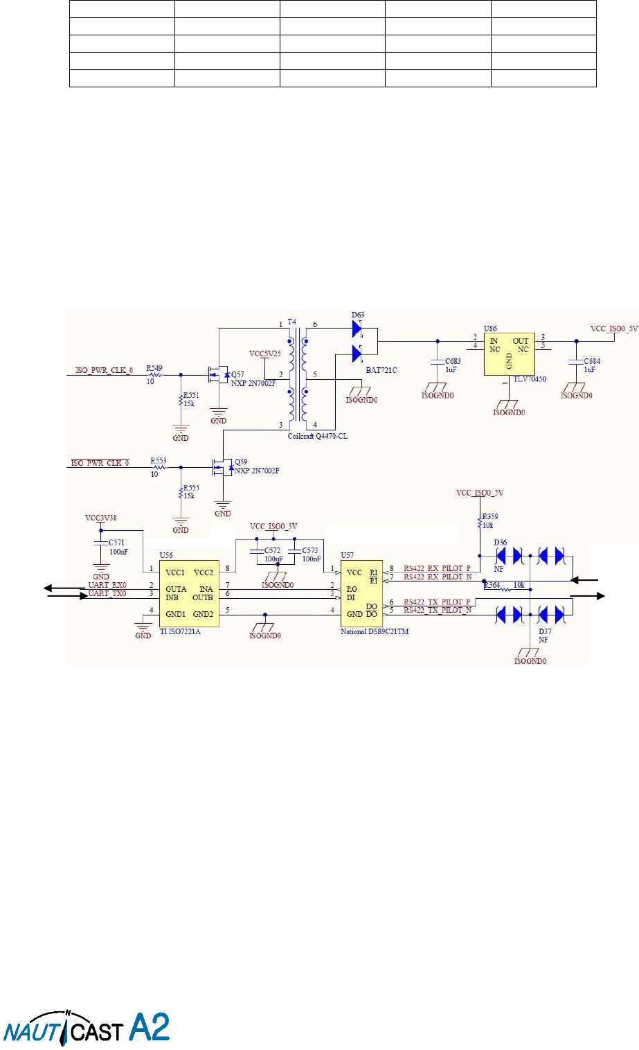
3.6.3 Schematics of a NAUTICAST A2 Serial Transceiver
Each of the RS422 serial interfaces on the NAUTICAST A2 fulfils the requirements of IEC 61162-2 and IEC
61993-2. A detailed schematic of one of the serial ports in the NAUTICAST A2 is shown below.
Figure 4 – Serial Port Schematics
ISO Power
Internal
Signals to AIS
To connected
equipment

Page 16 of 80 1001001-2EN A2 Product Manual 2_0
3.6.4 Data Interface Cable with open ends, 1001003
Pin
In/Out
Signal Name
Signal Type
Colour
1
Out
ECDIS - TxB (+)
RS422
White
2
Out
ECDIS - TxA (-)
RS422
Brown
3
In
Sensor1 - RxB (+)
RS422
Green
4
In
Sensor1 - RxA (-)
RS422
Yellow
5
In
Sensor2 - RxB (+)
RS422
Grey
6
In
Sensor2 - RxA (-)
RS422
Pink
7
In
Long Range - RxB (+)
RS422
Blue
8
In
Long Range - RxA (-)
RS422
Red
9
-
Long Range - GND
RS422
Black
10
-
ECDIS - GND
RS422
Violet
11
In
ECDIS – RxB (+)
RS422
Grey / Pink
12
In
ECDIS – RxA (-)
RS422
Red / Blue
13
-
Sensor1 – GND
RS422
White / Green
14
-
Sensor2 – GND
RS422
Brown / Green
15
In
Sensor3 – RxB (+)
RS422
White / Yellow
16
In
Sensor3 – RxA (-)
RS422
Yellow / Brown
17
Out
Long Range – TxB (+)
RS422
White / Grey
18
Out
Long Range – TxA (-)
RS422
Grey / Brown
19
-
Alarm Relay – GND
-
White / Pink
20
Out
Alarm Relay – Out
-
Pink / Brown
21
-
GND
-
White / Blue
22
-
-
-
Brown / Blue
23
-
Sensor3 – GND
RS422
White / Red
24
-
Alarm Relay - VCC
-
Brown / Red
25
In/Out
CAN (+)
Differential
CAN bus
White/Black
26
In/Out
CAN (-)
Differential
CAN bus
Brown/Black
Table 7 – 26-pin High Density D-sub
3.6.5 RS232 Data Cable
Pin
Signal Name
1
Not Connected
2
Tx (Transponder side)
3
Rx (Transponder side)
4
Not Connected
5
GND
6
Not Connected
7
Not Connected
8
Not Connected
9
Not Connected
Table 8 – 9-pin female D-sub
Page 17 of 80 1001001-2EN A2 Product Manual 2_0
3.6.6 Power Cable, 1001002
Pin
Signal Name
Colour
1
24VDC positive
Red
2
GND
Black
3
External Switch (R)
Brown
4
External Switch (F)
Orange
Table 9 – 4-pin male circular ConXall
3.6.7 External Switch
The Power Cable enables connection of an external switch to the NAUTICAST A2. This switch can be used as
a Silent switch or, if configured as an Inland AIS system, as a Blue sign switch.’
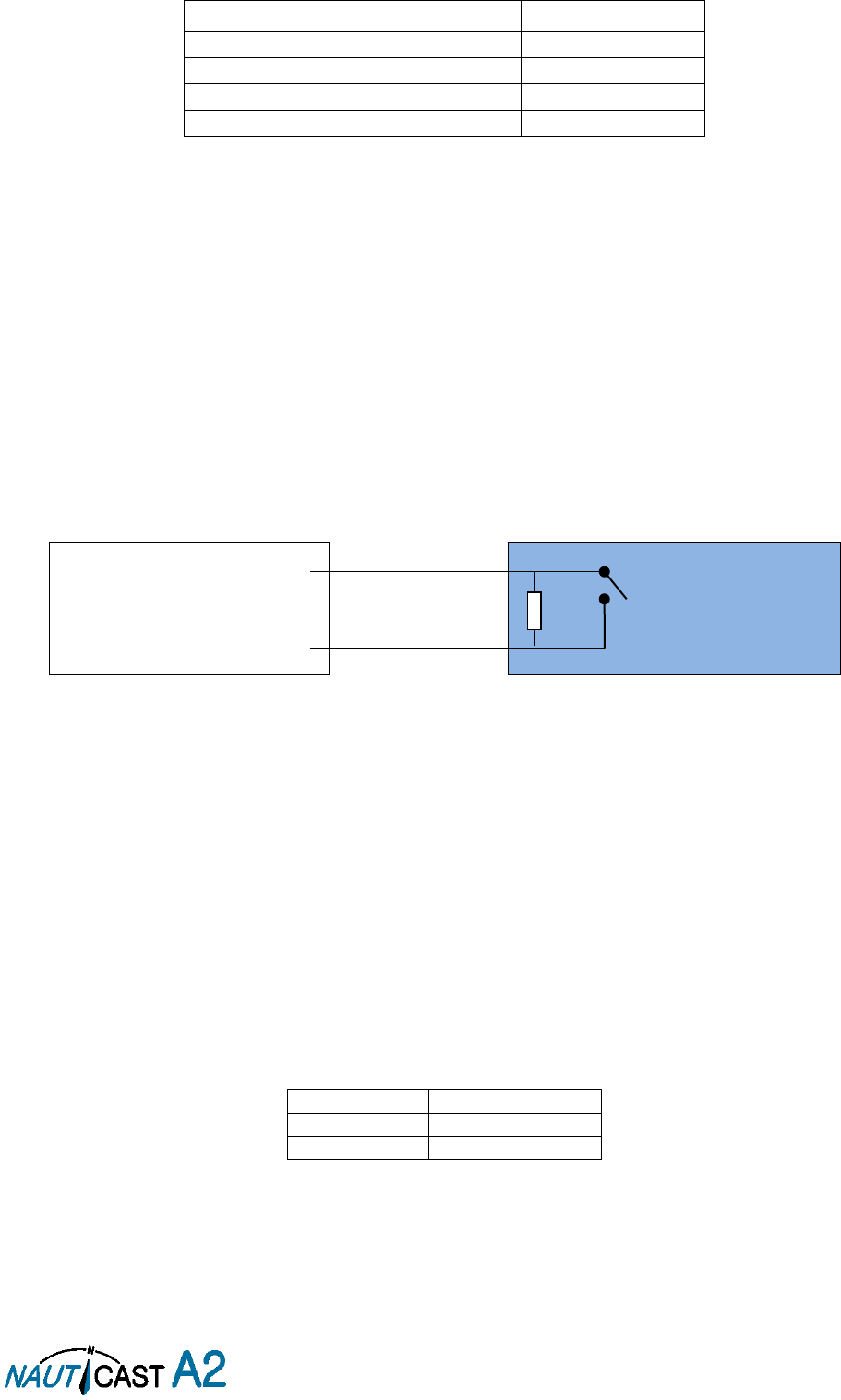
3.6.7.1 Blue Sign installation (Inland Mode only)
If the blue sign switch should be used, the parameter “External Switch” must be configured to “Blue Sign” in
Misc. Interface view accessed from
Main Menu Config Interfaces Miscellaneous
.
The status of the blue sign can be controlled by input on the brown and orange wires of the Power Cable.
The status of the Blue Sign will be read by the NAUTICAST A2 and output on the VHF data link when operating
in “Inland Mode” (see section 4.4.16 for more details). Connect the blue sign switch to pin 3 (brown wire) and
pin 4 (orange wire) of the Power Cable together with an external parallel resistor. When the switch is open,
blue sign will be off. When the switch is closed, blue sign will be on.
The external resistor value depends on the power supply voltage the NAUTICAST A2 is using:
12V: 2.2kΩ resistor, 10% tolerance, at least 1/8W power rating
24V: 10kΩ resistor, 10% tolerance, at least 1/8W power rating
Figure 5 – Blue Sign Switch
3.6.7.2 Silent switch installation
It is possible to connect a silent switch to the NAUTICAST A2 to quickly turn off transmissions.
If a silent switch is to be used, the parameter “External Switch” must be configured to “Silent Switch” in Misc.
Interface view accessed from
Main Menu Config Interfaces Miscellaneous
.
The silent switch should be connected in the same way as the blue sign switch. However, the external resistor
may be omitted for the silent switch.
When the circuit is closed (brown and orange wires connected with each other), the NAUTICAST A2 will
transmit as normal. When the circuit is open, the NAUTICAST A2 will be completely silent.
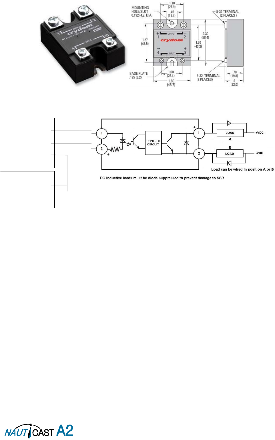
3.6.8 Alarm Relay
It is required that the AIS alarm output (relay) is connected to an audible alarm device or the ship’s alarm
system, if available.
Alternatively, the ship’s BIIT alarm system may use the alarm messages output on the AIS Presentation
Interface (PI) provided the alarm system is AIS compatible. The AIS Alarm Relay is either mounted directly on
a board or on the wall.
The alarm relay wires have the following colour codes in the 26-pole NAUTICAST A2 data interface cable:
RELAY VCC
Brown/Red
RELAY GND
White / Pink
RELAY OUT
Pink / Brown
Table 10 – Alarm Relay Wires
Figure 6 shows the alarm relay and its dimensions and explains how to connect the alarm relay to the data
cable and how to connect the load (Alarm Circuit) to the alarm relay. The operating voltage of the alarm relay
is 3 to 60 VDC with a load current of 0.1 to 2 A (3A when using a heat sink).
BLUE SIGN
SWITCH
Power Cable Pin 3
Power Cable Pin 4
External resistor
Page 18 of 80 1001001-2EN A2 Product Manual 2_0
Figure 6 – Alarm Relay
Transponder:
RELAY VCC
RELAY GND
RELAY OUT
Ext. Power Supply:
- (GND)
+12 to 32VDC

Page 19 of 80 1001001-2EN A2 Product Manual 2_0
3.7 System Configuration
When the physical and electrical installation of the system is complete, the NAUTICAST A2 needs to be
configured. The installer is required to set the parameters listed below. For detailed information about the
configuration parameters and how to set them, refer to section 4.2.1 and 4.4.
MMSI number (Maritime Mobile Service Identity)
IMO vessel number (should be set to zero for Inland vessels)
Call Sign
Ship Name
Ship Type (Only when operating in Class A mode)
Height Over Keel
Ship dimensions and antenna positions. Refer to section 4.4.4 Main Menu Config Ship Dimensions
for more information.
If the NAUTICAST A2 is operating in Inland mode, the following parameters also need to be configured:
ENI, Unique European Ship Number
ERI Ship Type (ERI code and standard AIS ship type will be set automatically by the NAUTICAST A2
when selecting an ERI Ship Type from list in Ship Static view.
Quality setting for SOG, COG and HDG. Should be set to low if no type approved sensor (e.g. a gyro
or speed log) is connected to NAUTICAST A2.
When the NAUTICAST A2 has been installed according to the procedures described in previous sections, it is
recommended to make a first functional check of the system. Check the following things to ensure that the
NAUTICAST A2 is fully functional.
Check the Transmitted Own Ship Data view to make sure that the configured data is sent by the
NAUTICAST A2 on the VHF link, refer to section 4.10 “View Transmitted Own Ship Information” for
more information.
Make sure that there are no unexpected active alarms in the alarm list, see section 4.18 “Alarms”.
Perform a communication test to ensure that the NAUTICAST A2 can send and receive messages from
other AIS transponders. Refer to section 4.25 “Communication Test” for information on how to perform
a communication test.
Page 20 of 80 1001001-2EN A2 Product Manual 2_0
4 Operation
4.1 System Mode
The NAUTICAST A2 can operate in two different system modes, Class A mode and Inland mode. The Class A
mode should be used for vessels falling under the carriage requirements of Chapter V of the International
Convention for the Safety of Life at Sea (SOLAS).
The Inland mode should be used for vessels travelling on European inland waterways that falls under the
carriage requirements of European River Information Services (RIS). When Inland mode is enabled, additional
views for ETA/RTA messaging and convoy settings will be enabled. The NAUTICAST A2 will also output binary
messages with Inland Static and Voyage data.
As default, the NAUTICAST A2 will operate in Class A mode. It is possible to switch system mode in the System
Settings view, see section 4.4.16 for more information.
4.2 LED’s and Controls
This section describes the controls and status LED’s on the front panel of the NAUTICAST A2. It is also possible
to connect a USB keyboard via the USB Host interface that can be found under the hatch of the front panel.
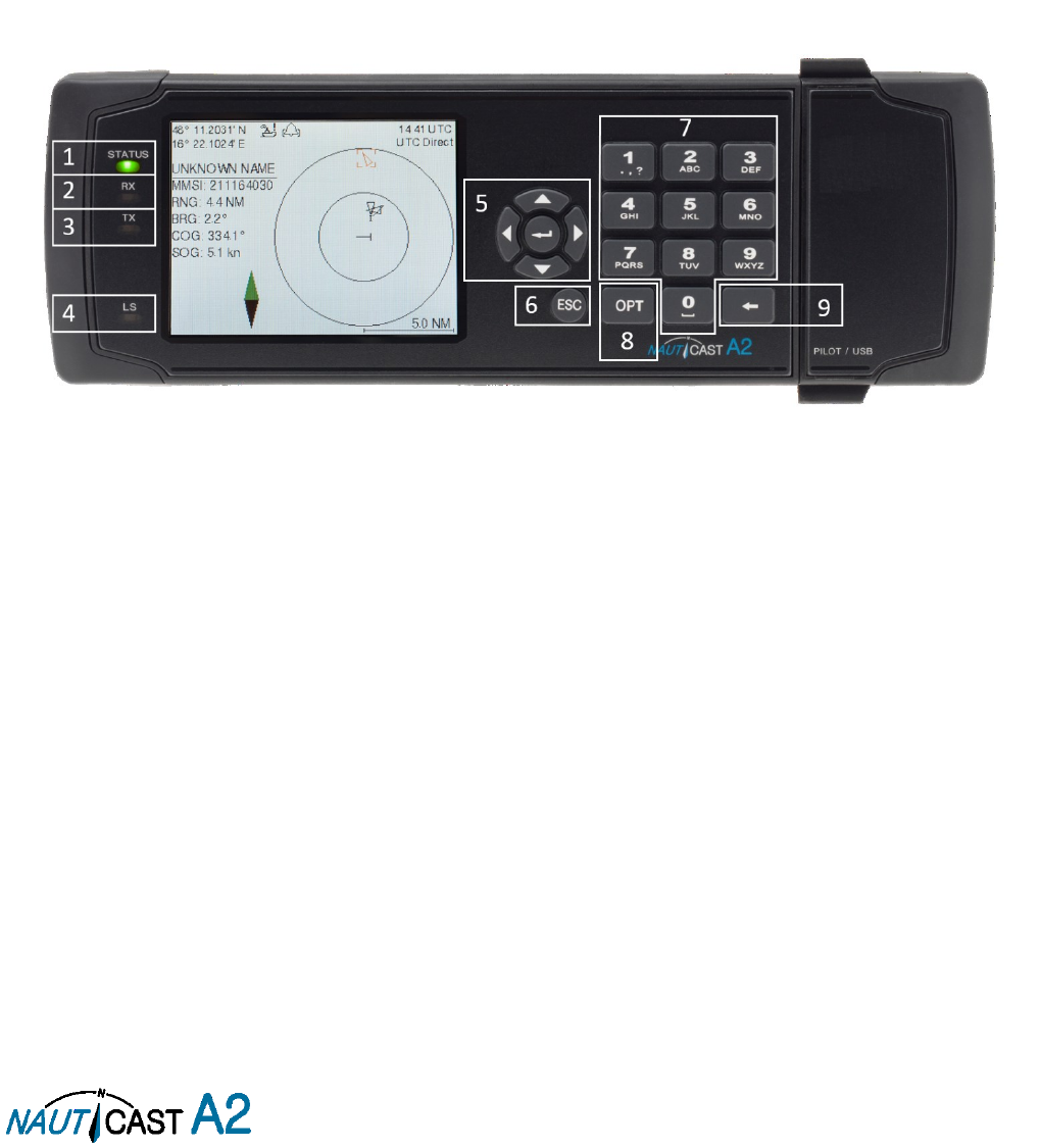
Figure 7 –Nauticast A2 Front View
1.
STATUS LED (multi-colour)
This LED is constant green when the transponder is operating and no alarms are active. The LED is constant
red if there is an active alarm and it is flashing red if there is an unacknowledged alarm.
2.
RX LED (yellow)
This LED is flashing yellow when the transponder is receiving a message on the VHF link.
3.
TX LED (red)
This LED is flashing red when the transponder is transmitting a message on the VHF link.
4.
LIGHT SENSOR
The light sensor will automatically dim the backlight of the display depending on measured input light to the
sensor.
5.
ARROW KEYPAD and ENTER
The arrow keypad (< > and ∧ ∨) is used to navigate in menus, lists and edit fields. The center button of the
keypad is an ENTER button which is used to select the highlighted choice in a menu, list or edit control.
6.
ESC
The ESC button is used to return to the previous screen or to cancel an edit change of a data field.
7.
ALPHANUMERIC KEYS
These keys are used for entering text and numbers. To write a number in a numeric field, press the key once.
To write a character in a text field, press once for the character associated with the key, twice for the second
character and so on. When pressing twice on key “1” when editing a text field, a popup view with special
characters appears. Choose the desired special character by using the ARROW KEYPAD and ENTER.

Page 21 of 80 1001001-2EN A2 Product Manual 2_0
When a USB keyboard is used, the normal letters, numbers and special characters can be used. Only American
keyboard layout is supported.
8.
OPT
This button is an “Option key” which is only active in some of the dialogs. When pressed, it gives the user a
list of options that can be performed on the highlighted item. In e.g. the Target List view the OPT button can
be used to send an SRM to the highlighted target. In the Main Menu view, the OPT button is used to quickly
change navigational status. When a USB keyboard is used, the ALT button of the keyboard corresponds to
OPT button on the NAUTICAST A2 keypad.
If the OPT button is pressed for more than 5 seconds, the visual settings in the NAUTICAST A2 will be restored
to default, i.e. LCD backlight, LED intensity and button backlight will all be 80% and day mode will be used.
9.
BACKSPACE
The BACKSPACE button is used to erase the character to the left of the marker in an edit field.
4.2.1 Change Settings of a Parameter
Several of the views in the NAUTICAST A2 contain parameters that can be edited. To edit a parameter, select
it by using the ARROW KEYPAD and press ENTER.
Then enter data in one of the following ways:
Numbers: Press the ALPHANUMERIC KEY that corresponds to each digit. To delete a digit, press
function key BACKSPACE. Some of the parameters are decimal numbers. The OPT button can then
be used to insert a decimal point.
Text: Press the ALPHANUMERIC KEY that corresponds to each character. Press the key once for
the first character, twice for the second character and so on. Press the key “1” twice to, where allowed,
bring up a menu for entering special characters. To delete a character, press function key
BACKSPACE. When entering passwords both lower and upper case letters can be used. To change
between upper and lower case letters, press function key OPT and choose “Caps Lock Off” or “Caps
Lock On”.
List of predefined values: Use the ∧ ∨ keys to select between the predefined values.
List of predefined values and numeric input: In some of the views like the AIS Message Send
view where it is possible to send an SRM to a target, it is possible to select an MMSI in a list of
predefined values. The predefined MMSI values are the MMSI numbers that have been received by
the transponder. It is also possible to enter a new MMSI number that has not been received yet. To
do this, simply input a numerical value with the ALPHANUMERIC KEYS.
Press ENTER when done. If desired, use the ARROW KEYPAD keys to select a new parameter to be edited,
or navigate to the Save/Send button located above the list of parameters and press ENTER to save the
parameters / send the message.
Use the ESC key to undo changes and to return to the previous view.
NOTE: DO NOT TURN OFF TRANSPONDER WITHIN 2 SECONDS OF A PARAMETER CHANGE!
Page 22 of 80 1001001-2EN A2 Product Manual 2_0
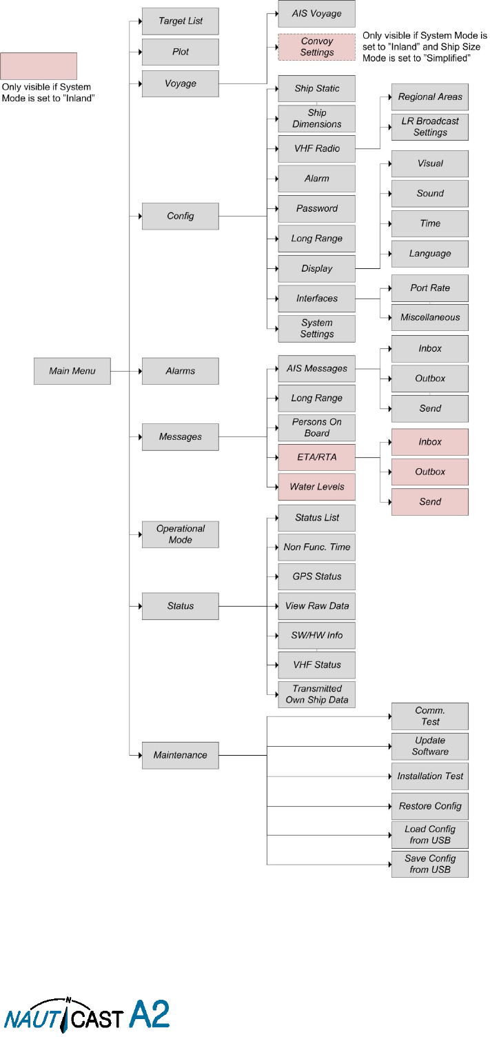
4.3 Main Menu – Tree View
Figure 8 – Menu Tree
Page 23 of 80 1001001-2EN A2 Product Manual 2_0
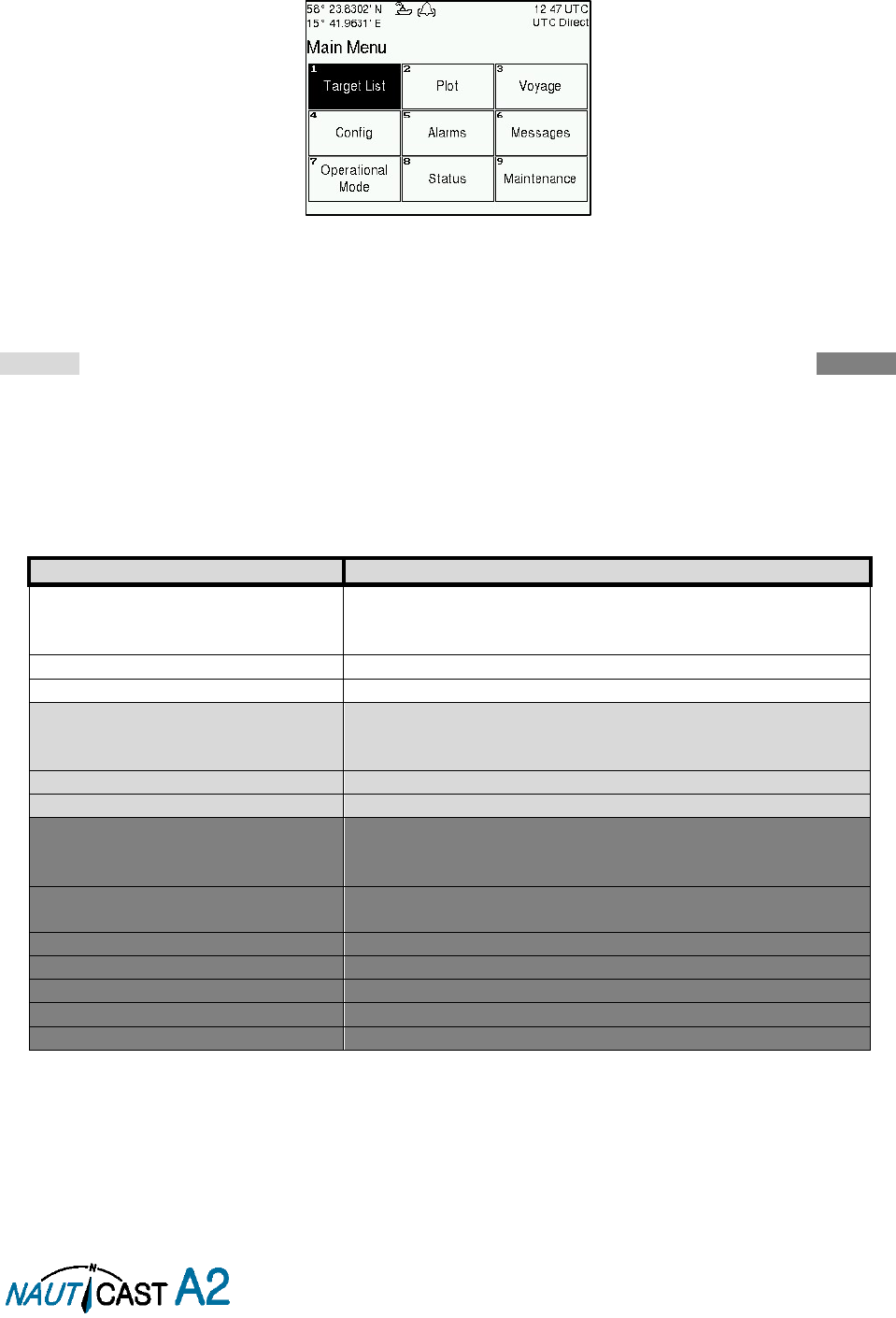
4.3.1 Navigating in Menus
Use the ARROW KEYPAD buttons < > and ∧ ∨ to navigate between the view buttons in the different menus.
Press the ENTER button to enter the currently selected view. It is also possible to directly select a view by
pressing the ALPHANUMERIC KEY that corresponds to the number in the upper left corner of the view
button.
Figure 9 – Main Menu
4.4 Configuration Parameters
This section describes the different configuration parameters that can be set in the NAUTICAST A2. Some of
the parameters will only be available when operating in “Class A” mode; these parameters are marked with
light grey. Parameters that are only available when operating in “Inland” mode are marked with dark grey.
Common parameters for both system modes are white.
4.4.1 Main Menu Voyage AIS Voyage
The parameters in AIS Voyage view are used for input of voyage specific information that is sent over the AIS
link. These parameters should typically be configured before each voyage.
When the NAUTICAST A2 system mode is set to “Inland”, additional voyage parameters for inland water way
voyages are available. The system mode can be configured in the System Settings view described in section
4.4.16.
Parameter Name
Description
Navigational Status
Changes the navigational status reported by own ship.
It is also possible to quickly change navigational status by
pressing the OPT button when standing in the Main Menu.
Destination
The destination for the current voyage
Estimated Time of Arrival (ETA)
The estimated time of arrival to destination of current voyage
Draught (Class A)
The vertical distance measured from the lowest point of a
ship’s hull to the water surface, in meters (one decimal
precision)
Persons on Board
Total number of persons on board
Hazardous Cargo (X,Y,Z,OS)
Classification of current cargo according to X,Y,Z,OS
Draught (Inland)
The vertical distance measured from the lowest point of a
ship’s hull to the water surface, in meters (two decimal
precision)
Air Draught
The vertical distance measured from the ship’s waterline to
the ship’s highest point, in meters (two decimal precision)
Hazardous Cargo (Blue Cones)
Blue cone classification of cargo
Loaded / Unloaded
Specifies if the ship cargo is loaded or unloaded
Crew Members
Number of crew members on board
Passengers
Number of passengers on board
Personnel
Number of shipboard personnel on board
Page 24 of 80 1001001-2EN A2 Product Manual 2_0
4.4.2 Main Menu Operational Mode
Parameter Name
Description
Tx Mode
This parameter determines the transmission of the
NAUTICAST A2. If set to “Silent”, the NAUTICAST A2 will be
completely silent on the VHF radio and it will not answer on
interrogations.
If a silent switch is used, this parameter will be locked and
“Silent Switch Used” will be displayed as parameter value.
4.4.3 Main Menu Config Ship Static
Parameter Name
Description
MMSI
Maritime Mobile Service Identity reported by own ship
IMO
International Maritime Organization number reported by own
ship
Ship Name
Ship name reported by own ship
Call Sign
Call sign reported by own ship.
Shall be set to ATIS code for Inland vessel installations.
Height over Keel
Height over keel in meters (one decimal precision).
Height over Keel information is sent as a response to an
“Extended Ship Static and Voyage Related Data” request
message.
Ship Type (IMO)
Type of Ship according to ITU-R M.1371-4. Both numerical
input and selection from list is possible.
ENI
Unique European Vessel Identification Number reported by
own ship
ERI Ship Type
Ship or combination type according to numeric ERI
classification. Both numerical input and selection from list is
possible. See chapter 10.1 “Inland ERI Ship Types” for
available types.
Quality Speed
Shall be set to low if no type approved speed sensor is
connected to transponder
Quality Course
Shall be set to low if no type approved course sensor is
connected to transponder
Quality HDG
Shall be set to low if no type approved heading sensor is
connected to transponder
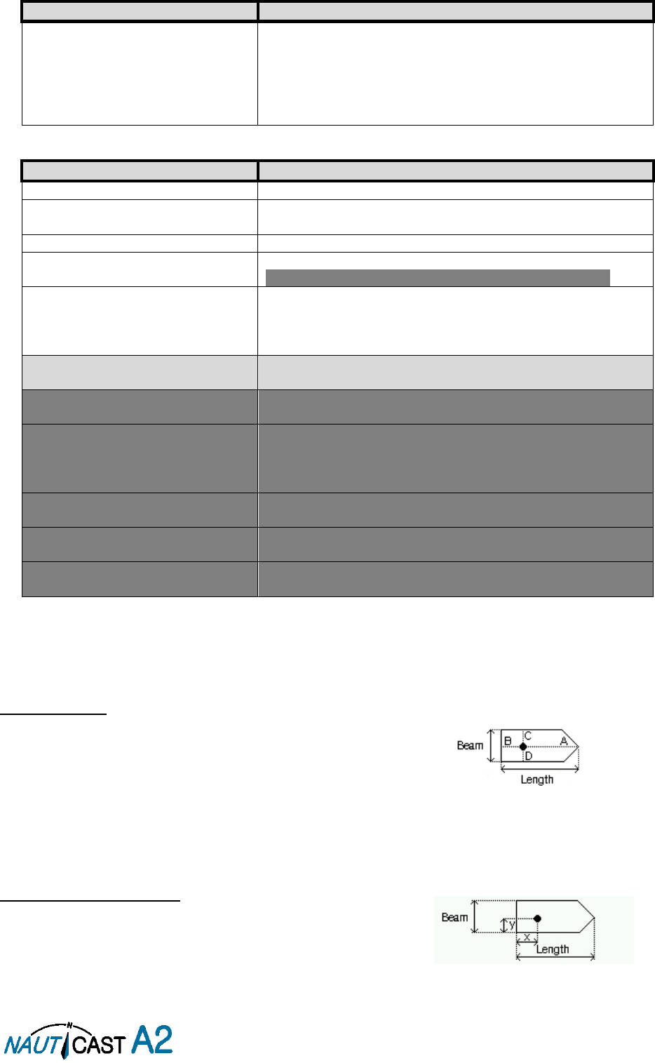
4.4.4 Main Menu Config Ship Dimensions
The parameters in the Ship Dimensions view depends on the configuration parameter “Ship Size Mode” in the
Misc Interfaces view. The Ship Size Mode parameter can be set to either Standard or Simplified (default). The
Ship Size Mode affects how the user should input ship size and antenna position information and how it is
interpreted.
Standard Mode
In this mode the user must input:
Convoy/ship length
[m] (one decimal precision)
Convoy/ship beam
[m] (one decimal precision)
A, B, C, D
for internal antenna [m]
A, B, C, D
for external antenna [m]
It is the users responsibility to input correctly rounded data (
A+B
=
Convoy/ship length
rounded up,
C+D
=
Convoy/ship beam
rounded up).
If the user inputs data which is not correctly rounded the “Ship size mismatch” alarm will be activated.
The output on the AIS data link will be exactly the values input by the user.
Simplified Mode (default)
In this mode the user inputs:
Ship length
[m] (one decimal precision)
Ship beam
[m] (one decimal precision)
X, Y
for internal antenna relative to ship [m] (one decimal precision)
X, Y
for external antenna relative to ship [m] (one decimal precision)
Page 25 of 80 1001001-2EN A2 Product Manual 2_0
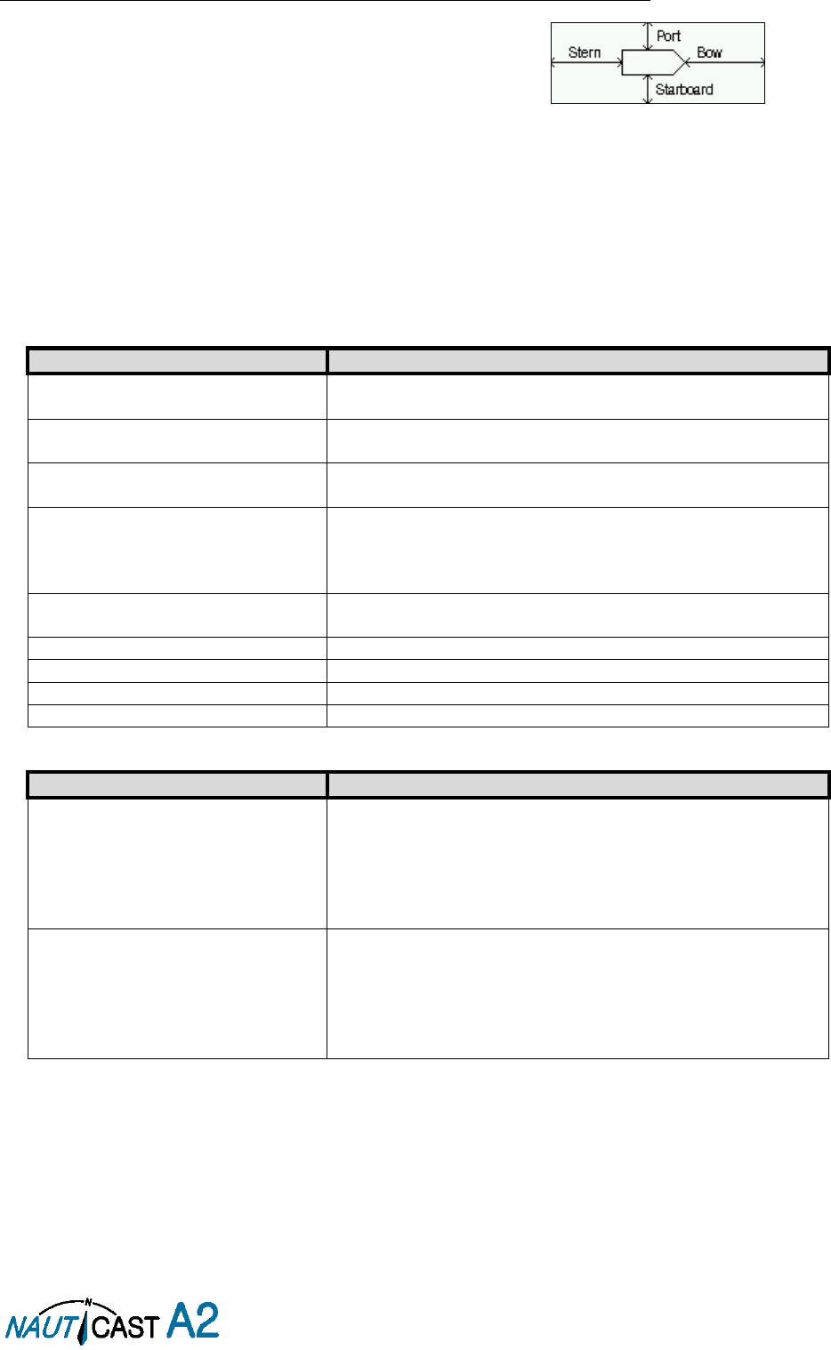
When operating in Inland Mode, extra convoy size can be added to ship dimension
Extra convoy size on each side (value = 0 if convoy not used):
Bow
[m] (one decimal precision)
Stern
[m] (one decimal precision)
Port side
[m] (one decimal precision)
Starboard
[m] (one decimal precision)
The extra convoy parameters can be configured from Main MenuVoyageConvoy Settings when the
Ship Size Mode is set to “Simplified”.
In this mode there is no way for the user to input mismatching data, all parameters uses the same precision
and each measurement is entered only once (in standard mode it is for example possible to enter three
different lengths of ship:
Convoy/ship length, internal A+B
and
external A+B
). In simplified mode the
transponder will automatically calculate and correctly round the A, B, C and D values reported on the VHF link.
4.4.5 Main Menu Config VHF Radio Regional Areas
This view shows the regional areas set in the transponder. To make a new regional area or to edit or delete
an existing regional area, press the OPT button and choose the desired action. The following parameters can
be edited when “New Area” or “Edit Area” is chosen:
Parameter Name
Description
Channel A
The channel number for AIS channel A (2087 = default) that
should be used in the regional area.
Channel B
The channel number for AIS channel B (2088 = default) that
should be used in the regional area.
Zone Size
The transitional zone size of the regional area in nautical miles
(NM).
Tx Mode
Decides on which channels the transponder will use when
transmitting in the regional area.
When set to “Silent”, the transponder will stop automatic
transmissions on AIS channels A and B.
Power
Output power for the transponder in the regional area. High
= 12.5 W, Low = 1 W.
LAT NE
The latitude for the North East corner of the regional area
LON NE
The longitude for the North East corner of the regional area
LAT SW
The latitude for the South West corner of the regional area
LON SW
The longitude for the South West corner of the regional area
4.4.6 Main Menu Config VHF Radio LR Broadcast Settings
Parameter Name
Description
LR Broadcast Ch. 1
The first channel number for broadcasting long range
message 27. The message is sent every 6 minutes on each
channel so if both channels are configured a message 27 will
be broadcasted every 3 minutes. If this parameter is set to
zero no long range broadcast transmissions will be sent on
this channel.
LR Broadcast Ch. 2
The second channel number for broadcasting long range
message 27. The message is sent every 6 minutes on each
channel so if both channels are configured a message 27 will
be broadcasted every 3 minutes. If this parameter is set to
zero no long range broadcast transmissions will be sent on
this channel.
4.4.7 Main Menu Config Alarm
In this view all alarms can be configured to either “Enabled” or “Disabled”. When the alarm is enabled, an
active alarm will affect the external alarm relay, the buzzer in the NAUTICAST A2 and show a popup dialog in
the display. When the alarm is set to disabled it will not affect anything when the alarm becomes active. For
more information about the alarm view, refer to section 4.18 “Alarms”. For a list of all the alarms that can
occur, refer to section 7.3 “Troubleshooting with Alarm Messages.”

Page 26 of 80 1001001-2EN A2 Product Manual 2_0
4.4.8 Main Menu Config Password
Parameter Name
Description
New User Password
Changes the user level password for the NAUTICAST A2.
The default user level password is “user”
New Admin Password
Changes the admin level password for the NAUTICAST A2.
The default admin level password is “admin”
Restore Code
It is possible to restore both user password and admin
password to the default values above with a secret restore
code.
To obtain the restore code, contact Nauticast Technical
Support and be prepared to provide the serial number of the
transponder unit.
4.4.9 Main Menu Config Long Range
Parameter Name
Description
Reply Mode
When set to “Auto” the NAUTICAST A2 will automatically
respond to any Long Range interrogation messages.
When set to “Manual” the operator is responsible for sending
a response or refusal to any Long Range interrogation
message. This can be done from the
Long Range
view that is
accessed from
Main Menu Messages Long Range
. For
more information see section 4.14 “Long Range
Interrogations”.
The information that is sent in a response is automatically
filled in by the NAUTICAST A2 depending on the Long Range
filter settings (the parameters below).
Ship ID (A)
Filter setting that defines if a Long Range response message
should include ship name, call sign and IMO number.
Message Date/Time (B)
Filter setting that defines if a Long Range response message
should include information about date and time of message
composition.
Latitude / Longitude (C)
Filter setting that defines if a Long Range response message
should include position.
Course Over Ground (E)
Filter setting that defines if a Long Range response message
should include COG.
Speed Over Ground (F)
Filter setting that defines if a Long Range response message
should include SOG.
Destination And ETA (I)
Filter setting that defines if a Long Range response message
should include destination and ETA.
Draught (O)
Filter setting that defines if a Long Range response message
should include draught.
Ship Type And Cargo (P)
Filter setting that defines if a Long Range response message
should include ship type and cargo information.
Ship Size And Type (U)
Filter setting that defines if a Long Range response message
should include ship’s length, beam and type.
Persons On Board (W)
Filter setting that defines if a Long Range response message
should include number of persons on board.

Page 27 of 80 1001001-2EN A2 Product Manual 2_0
4.4.10 Main Menu Config Display Visual
It is possible to completely turn off the backlight on LCD, buttons and LED’s. It may then be difficult to read
the NAUTICAST A2 display and find the way to the correct configuration parameter in order to increase the
backlight again. If this should happen, it is possible to hold down the OPT button for 5 seconds to restore the
backlight to 80%.
Parameter Name
Description
Dimming Mode
If set to “Manual”, the LCD backlight, button backlight and
LED brightness are controlled by the user with the parameters
described below.
If set to “Automatic”, the LCD backlight, button backlight and
LED brightness will automatically be controlled with the light
sensor on the front of the NAUTICAST A2. The less ambient
light registered by the light sensor, the lower percentage of
backlight and brightness will be used.
Toggle Day/Night
Toggle between day or night mode. In Day mode the display
background is white and in night mode the background is
black. There are also separate settings for the LCD backlight,
LED intensity and button backlight in the different day/night
modes.
Backlight
Changes the LCD backlight where 0% is completely turned off
and 100 % is maximum brightness.
LED Light Intensity
Changes the light intensity of the three LED’s on the front of
the NAUTICAST A2.
It is possible to turn off the LED’s completely by setting a 0%
light intensity. However, if there is an active, unacknowledged
alarm in the NAUTICAST A2, the light intensity of LED’s will
temporarily be set to 10% until the alarm is acknowledged.
Button Illumination
Changes the brightness of the button backlight on the
NAUTICAST A2.
4.4.11 Main Menu Config Display Sound
Parameter Name
Description
Alarm Waiting For ACK
Determines how the NAUTICAST A2 sound buzzer should
behave when an alarm is active and waiting for
acknowledgement. This setting does NOT affect the
behavior of the alarm relay or any external alarm
system.
Long Range Message
Controls the behaviour of the NAUTICAST A2 sound buzzer
when an LR interrogation message is received.
AIS Message
Controls the behaviour of the NAUTICAST A2 sound buzzer
when a SRM or binary text message is received.
Inland RTA
Controls the behaviour of the NAUTICAST A2 sound buzzer
when an Inland RTA (Recommended Time of Arrival) message
is received.
4.4.12 Main Menu Config Display Time
Parameter Name
Description
Time Zone
This parameter defines if the times that are displayed in the
NAUTICAST A2 should be in UTC or LOC (local) time. If local
time is chosen, the offset from UTC must be specified with the
three parameters listed below.
Offset sign
The sign of the local time offset from UTC.
Hours
The local time hour offset from UTC.
Minutes
The local time minute offset from UTC.

Page 28 of 80 1001001-2EN A2 Product Manual 2_0
4.4.13 Main Menu Config Interface Language
Parameter Name
Description
Language
Changes the language in all the menus and views of the
NAUTICAST A2. The changes will take effect immediately
when pressing “Save”.
4.4.14 Main Menu Config Interface Port Rate
Parameter Name
Description
Baud Rate
Changes the baud rate (bits per second) for the corresponding
serial port.
Checksum
When set to “Required”, all messages that are input on the
corresponding serial port to the NAUTICAST A2 must have a
valid checksum.
When set to “Disabled”, messages both with and without
checksum are accepted on the corresponding serial port.
4.4.15 Main Menu Config Interface Miscellaneous
Parameter Name
Description
SSD Password
Changes the value of the SSD password level. When set to
“None”, no password is required when configuring the
transponder with an SSD sentence from e.g. an ECDIS via the
serial port interface.
When set to “User”, an SPW sentence with the correct user
level password must be sent before the SSD on the serial port
interface.
Ship Size Mode
This affects how the user should input the ship size, convoy
size and antenna positions. See section 4.4.4 for more details.
AIS GPS Output Port
Defines on which serial port the NAUTICAST A2 should output
data from the internal GPS. When set to “None” no internal
GPS data will be output.
External Switch
This parameter specifies if there is a blue sign switch or silent
switch connected to the orange and brown wires of the
NAUTICAST A2 Power Cable.
If no switch is used, set the parameter to “No Function”.
See sections 3.6.7.1 and 3.6.7.2 for more information about
the blue sign switch and silent switch.
Require Text Msg ACK
This parameter determines if an ACK msg is required as a
response when sending addressed binary text messages to
another target.
Automatic PoB Broadcast
Enable automatic 6 minute periodic broadcast of passenger
information. See section 4.13 for details on message types.
4.4.16 Main Menu Config System Settings
Parameter Name
Description
System Mode
Determines if the NAUTICAST A2 should operate as a Class A
transponder or as an Inland transponder. This parameter
affects which config parameters and menus that are visible in
the system.
Range Unit
This parameter determines the unit for the range value of
targets in the Target List, Extended Info view and Plot view.
The range value can be calculated in nautical mile (NM),
kilometre (km) or statute mile (Sm).
Speed Unit
This parameter determines the unit for the SOG value of
targets in Extended Info view and Plot view. The SOG values
can be calculated in knots (kn), kilometres per hour (km/h) or
miles per hour (mph).
Plot Compass
This parameter determines how the plot of AIS targets should
be oriented.
Page 29 of 80 1001001-2EN A2 Product Manual 2_0
If set to “North Always Up”, the plot will always have north up
and own ship will rotate according to heading input.
If set to “Own Ship Bow Always Up”, the plot will always have
own ship pointing up and rotate the rest of the plot according
to heading input.
4.4.17 Main Menu Maintenance Installation Test
Parameter Name
Description
Sensor Data Source
This parameter specifies which port the NAUTICAST A2 should
use as its external sensor source. The default value of this
parameter is “Automatic” which means that the NAUTICAST
A2 will accept sensor information on any port and use the
information on the port with highest priority.
If Sensor Data Source is set to anything other than
“Automatic”, the NAUTICAST A2 will only accept sensor
information if it comes from the port specified by this
parameter.
The parameter reverts to “Automatic” after a reboot.
SART Test Mode
This parameter determines if SART Test targets should be
displayed in Target List and Plot views of the NAUTICAST A2.
It also controls if connected systems, for example ECDIS, will
receive SART Test targets.
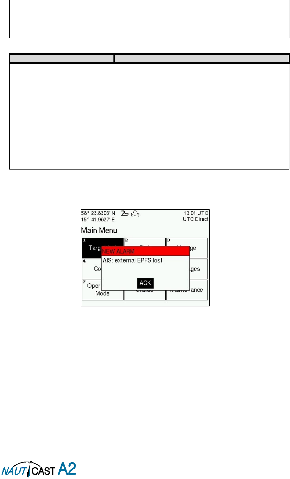
4.5 Alarm and Alert Pop-ups
The NAUTICAST A2 features alarm and alert pop-ups that can appear any time during operation. To
acknowledge an alarm or alert message, press ENTER. An example of an alarm message is shown below.
Figure 10 – New Alarm Message
Page 30 of 80 1001001-2EN A2 Product Manual 2_0
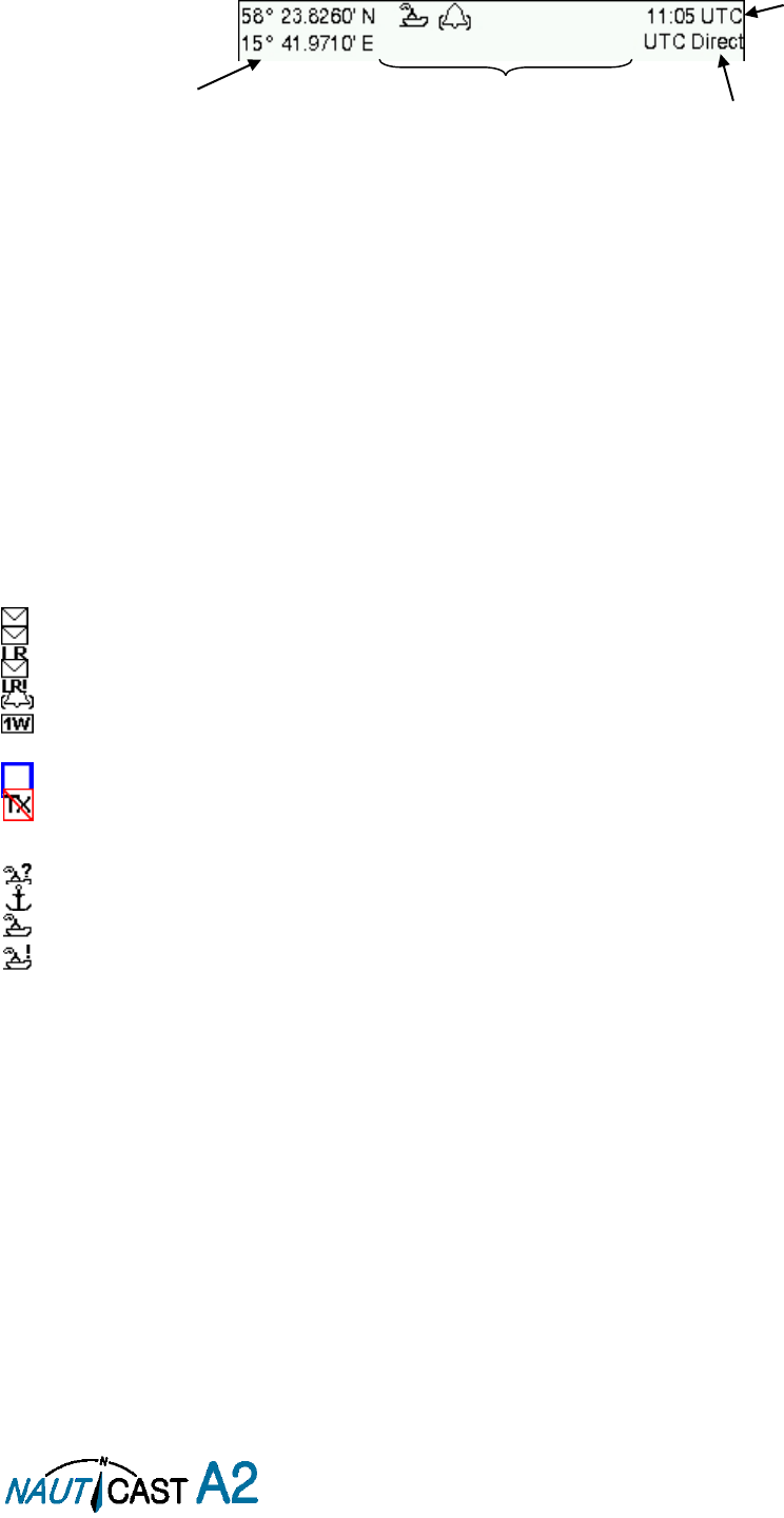
4.6 Status Bar
The top of the screen of the NAUTICAST A2 always displays a summary of the system’s status. See illustration
below.
Figure 11 – Status Bar
If a valid navigation position is available, it is displayed to the left. The status icons are displayed in the middle
and the current time is shown to the right. Time is either UTC or local (LOC). Beneath the current time there
is also information about the transponder’s synchronization state.
The synchronization state can be:
UTC Direct – This is the normal state where the NAUTICAST A2 gets the UTC time from its own
internal GPS receiver.
Indirect Synchronization – The NAUTICAST A2 is synchronizing based on receipt of data from
other AIS transmitters.
NOTE: It is possible to be in Indirect Synchronization but still have a valid position in the upper left corner of
the status bar. The position information may be from an external GPS sensor, but UTC Direct synchronization
can only be taken from the internal GPS receiver.
4.7 Status Icons
The status icons that can be displayed are:
Unread message (safety related message, text message or RTA)
Unread Long Range message (automatic reply)
Unread Long Range message (manual reply)
Active alarms
1W mode (Indicates 1 Watt TX mode for Tankers is enabled.) See NOTE below for details.
Blue Sign On (only available when System Mode is “Inland”)
Blue Sign Off (only available when System Mode is “Inland”)
Silent Mode activated, either with Tx Mode parameter or silent switch.
Navigational status, being one of:
Navigational status is undefined
At anchor or moored
Under way using engine
Navigational status is one of: Not under command, Restricted manoeuvrability, Constrained by her
draught, Aground, Engaged in fishing, Under way sailing, Reserved for future use.
NOTE: The transponder will automatically engage 1W mode when the following conditions are met: Ship type
= Tanker, Nav Status = Moored and SOG <= 3 knots, otherwise 1W mode will be automatically disengaged.
The Tanker 1W mode is fully automatic and cannot be disengaged by other external control.
Current position
Status icons
Current time
synchronization state
Current time
Page 31 of 80 1001001-2EN A2 Product Manual 2_0
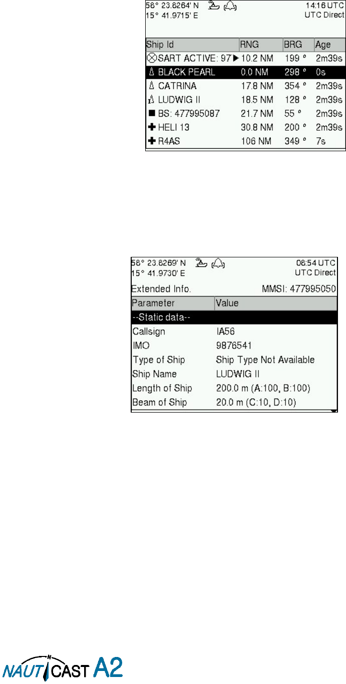
4.8 View Remote Ship Information
The NAUTICAST A2 will power up in
Target List
view. This view, also referred to as the
minimal display
, is
accessed from the
Main Menu
view. The
Main Menu
view can be reached by pressing ESC repeatedly from
any other view. The
Target List
view displays a list of all targets sorted by range from own ship (closest first).
The list includes MMSI or ship’s name (Ship Id), range (RNG), bearing (BRG) and time since last report was
received (Age) for each AIS target received by the system.
Figure 12 – Target List
The OPT button can be used in the
Target List
view to send a safety related message (SRM) to the selected
target. For more information about AIS messages, refer to section 4.12.
For extended information about a target in the list, select the ship with the ∧ ∨ key and press ENTER.
The
Extended Information
view includes static, dynamic and voyage related data for the selected target. In
this view it is also possible to query for static and voyage data as well as persons on board information by
using the OPT button.
Figure 13 – Extended Info
Press
ESC
to return to
Target List
view.
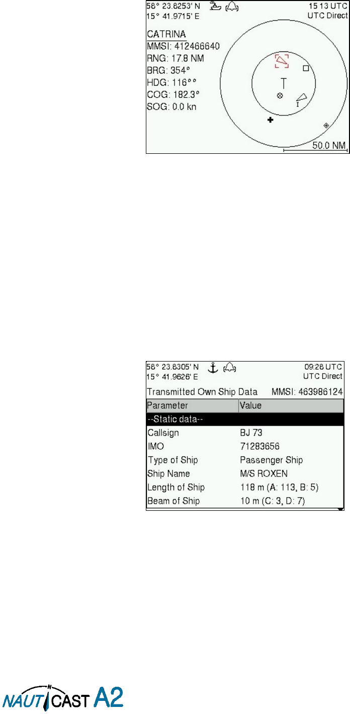
Page 32 of 80 1001001-2EN A2 Product Manual 2_0
4.9 View Plot of Targets
The location of targets relative to your own ship is visualized in the
Plot
view. The view is accessed from the
Main Menu
view. Use the
ARROW KEYPAD
< > to select any of the targets on the display or ∧ ∨ to Zoom
In and Zoom Out.
Figure 14 – Target Plot
For extended information about a target select it using the < > key and press ENTER.
The own ship target is displayed as a ‘T’ shaped symbol. Class B targets are indicated by a ‘B’ appended to
the target icon and Inland targets are indicated by either an ‘I’ or by a blue sign symbol appended to the
target (not shown in the figure above).
The OPT button can be used in the
Plot
view to send a safety related message (SRM) to the selected target.
For more information about AIS messages, refer to section 4.12.
4.10 View Transmitted Own Ship Information
The information transmitted by the NAUTICAST A2 on the VHF link is viewed in the
Transmitted Own Ship
Data
view. This view is accessed from
Main Menu Status
view and includes the static, dynamic and voyage
related data actually sent by the NAUTICAST A2. The view reflects the contents of the last transmitted AIS
message, thus there may be some delay from the time the parameters are changed until they are displayed
in the
Transmitted Own Ship Data
view.
Figure 15 – Transmitted Own Ship Data
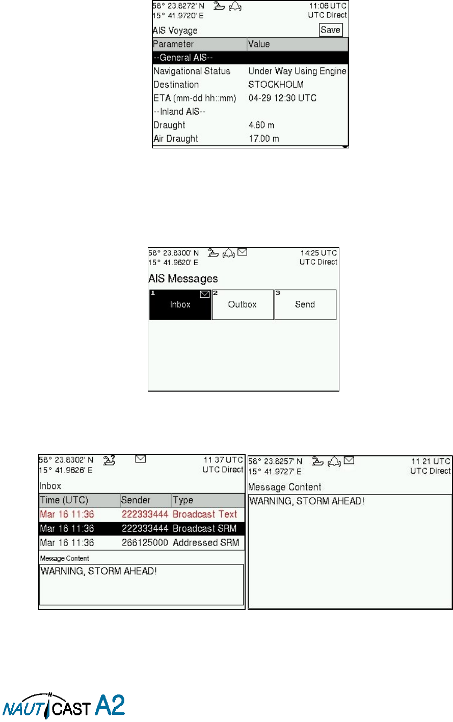
Page 33 of 80 1001001-2EN A2 Product Manual 2_0
4.11 Enter and Read Voyage Related Information
Voyage related information (for transmit via AIS) is displayed in the
AIS Voyage
view. The view is accessed
from
Main MenuVoyageAIS Voyage
. Voyage related data includes destination, estimated time of arrival
(ETA) and number of people aboard.
Figure 16 – AIS Voyage
4.12 Handling Safety Related Messages (SRM) and Text Messages
Safety related messages (SRMs) and text messages can be sent to specific targets (addressed messages) or
broadcast to all targets. The Inbox, Outbox and Send views for SRMs and text messages can be accessed from
Main MenuMessagesAIS Messages
.
Figure 17 - AIS Messages
4.12.1 Read Received Messages
Received messages can be accessed in the
Inbox
view. Unread SRMs and text messages are indicated with a
letter icon in the status bar and are marked with red color in the inbox.
Figure 18 – AIS Message Inbox
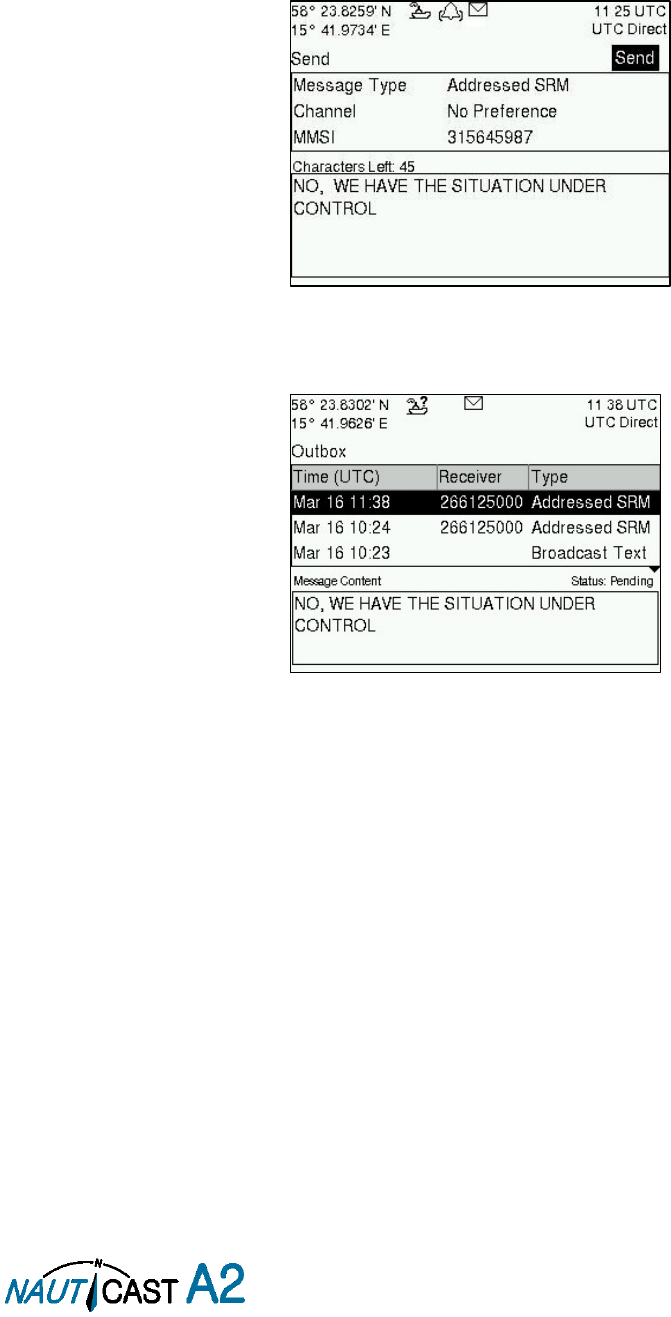
Page 34 of 80 1001001-2EN A2 Product Manual 2_0
Select a message with ARROW KEYPAD buttons ∧ ∨. A preview of the selected message is shown at the
bottom of the screen. To read the entire message and mark it as being read, press ENTER. When the message
is read, navigate back to the inbox by pressing ESC.
It is possible to reply to, forward or delete the selected message by pressing the OPT button.
4.12.2 Send SRMs and Text Messages
SRMs are composed and sent in the Send view accessed from
Main MenuMessagesAIS MessagesSend
.
Use the ARROW KEYPAD buttons ∧ ∨ to navigate between the text input field, list of parameters and “Send”
button.
Figure 19 – AIS Message Send view
Sent messages can be viewed in the
Outbox
view accessed from
Main MenuMessagesAIS
MessagesOutbox
.
Figure 20 – AIS Message Outbox
4.13 Send Persons On Board
In the
Send Persons On Board
view it is possible to send information about the number of persons on board
(PoB) to another vessel. The PoB message can be sent as either addressed or broadcast. The PoB message
can also be sent in two different versions:
The IMO version sends the total number of persons on board as a binary message with international FI 16.
The Inland (IWW) version sends a message with number of crew, personnel and passengers as a binary
message with inland FI 55. The information sent in the messages is automatically filled in by the NAUTICAST
A2 depending on the voyage configuration made in
Main MenuVoyageAIS Voyage.
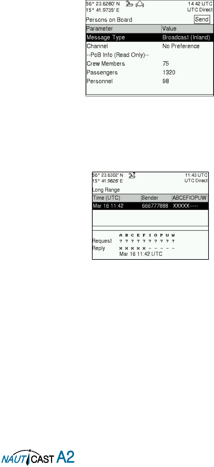
Page 35 of 80 1001001-2EN A2 Product Manual 2_0
Figure 21 – Persons On Board
4.14 Long Range Interrogations
An AIS transponder can receive long range interrogation messages to poll for certain information. A received
interrogation message is indicated by a LR icon in the status bar. If the “Long Range Reply Mode” parameter
has been configured to “Auto”, the NAUTICAST A2 will automatically send a response to the interrogation. If
the “Long Range Reply Mode” parameter is set to “Manual”, the operator must send a response or refusal
from the
Long Range Message
view accessed from
Main Menu Messages Long Range
. For more
information about the “Reply Mode” parameter and Long Range filter settings, see section 4.4.9.
Figure 22 – Long Range
To send a reply or refusal to the interrogation or to delete an interrogation from the message list, use the
ARROW KEYPAD buttons ∧ ∨ to mark the desired interrogation and then press the OPT button and choose
the desired option.
The Long Range view uses the following symbols to indicate the status of a request or reply message:
? – The information is requested by the sender
X – The information is available and provided
! – The information requested is refused
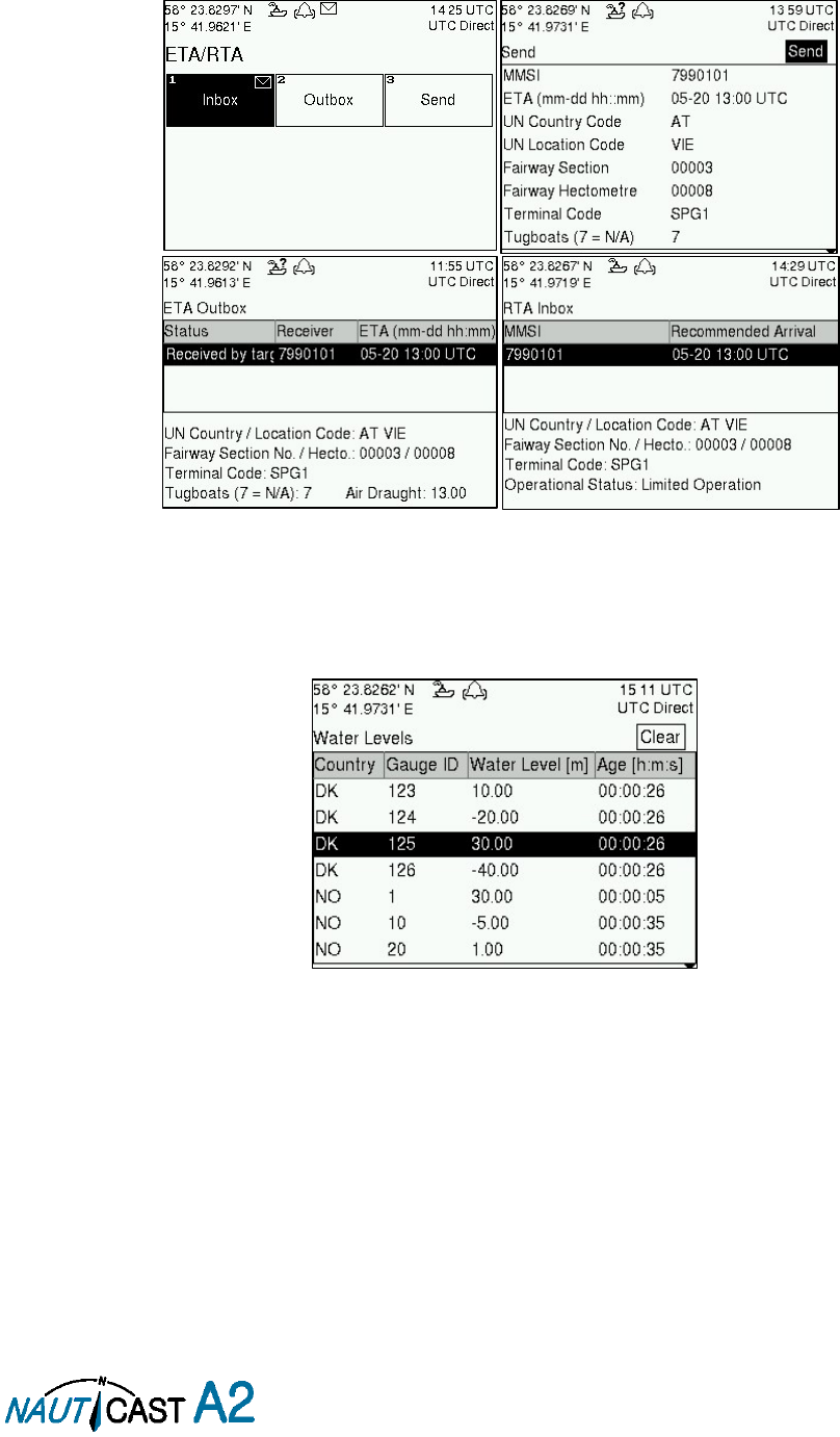
Page 36 of 80 1001001-2EN A2 Product Manual 2_0
4.15 Inland ETA and RTA
The NAUTICAST A2 has capability to send Inland ETA (Estimated Time of Arrival) messages and receive Inland
RTA (Recommended Time of Arrival) messages which are used when communicating with ports, locks and
bridges on the inland water ways. This is done from the
ETA/RTA
view that can be accessed from
Main Menu
Messages ETA/RTA
. Sent ETA messages can be viewed in the
Outbox
view, received RTA messages can
be viewed in the
Inbox
view and new ETA messages can be composed in the
Send
view.
Figure 23 – ETA/RTA
4.16 Inland Water Levels
The NAUTICAST A2 can receive and display Inland water levels messages. All received water levels messages
can be viewed in the
Water Levels
view that can be accessed from
Main Menu Messages Water Levels
.
Figure 24 – Inland Water Levels
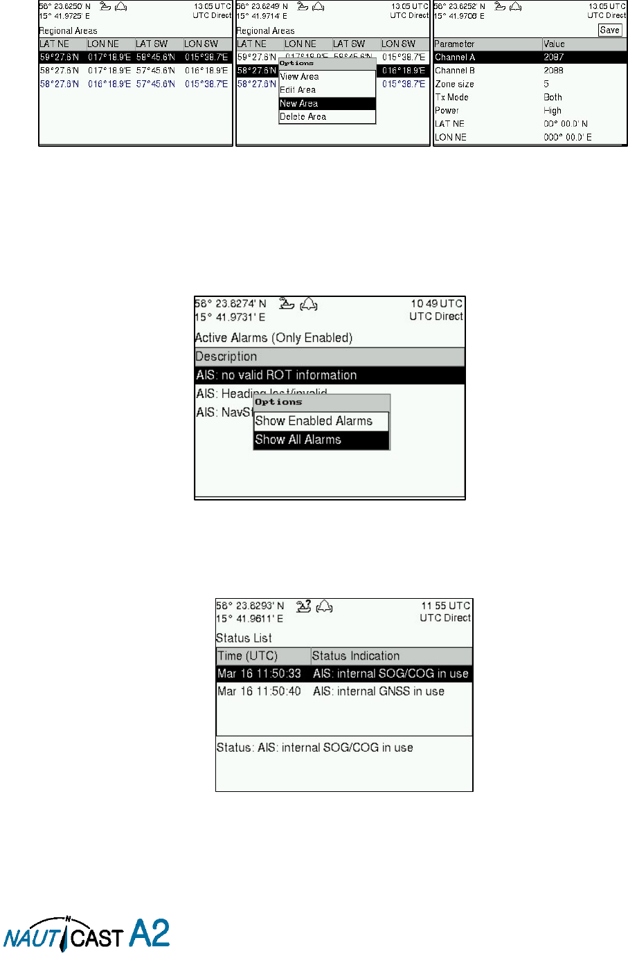
Page 37 of 80 1001001-2EN A2 Product Manual 2_0
4.17 Regional Areas
All regional areas that are stored in the NAUTICAST A2 can be viewed in the Regional Areas view which is
accessed from
Main Menu Config VHF Radio Regional Areas
. The list shows the north east and south
west corners of the area. The area is marked with blue color if it is in use by the NAUTICAST A2. To view
more information about the area, edit the area or create a new area, press the OPT button and choose the
desired option.
Figure 25 – Regional Areas
4.18 Alarms
All currently active and enabled alarms are shown in the
Alarm
view that can be accessed from
Main
MenuAlarms
. As default, only alarms that are configured as “Enabled” will be shown in the list. It is possible
to also show disabled active alarms by pressing OPT button and choose “Show All Alarms”. For a list of all
alarms, see section 7.3.
Figure 26 - Alarms
4.19 Status List
Current status indications are listed in the
Status List
view that can be accessed from
Main Menu Status
Status List
. The different status indications that can occur are listed in section 7.8.
Figure 27 - Status List
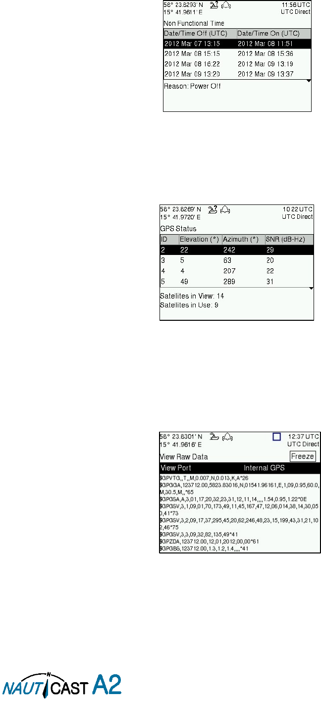
Page 38 of 80 1001001-2EN A2 Product Manual 2_0
4.20 Non Functional Time
This view displays information about times when the NAUTICAST A2 has been turned off or for some other
reason not been transmitting for more than 15 minutes. The view is accessed from
Main Menu Status
Non Func. Time
.
Figure 28 - Non Functional Time
4.21 GPS Status
This view displays the satellites received by the NAUTICAST A2 internal GPS receiver. The list is sorted by the
satellites ID (PRN number) and shows elevation, azimuth and signal to noise ratio (SNR) for each satellite.
The view also displays the total number of satellites in view and the total number of satellites used in the
position calculation reported by GGA sentence.
Figure 29 – GPS Status
4.22 View Raw Data
This view displays the incoming data on the selected serial port. It is also possible to pause the data on the
screen by pressing the “Freeze” button. Use the ARROW KEYPAD buttons ∧ ∨ to navigate to the Freeze
button and press ENTER. The View Raw Data view can be a helpful tool when trouble shooting the system to
see what sensor input is actually received on each port. The view can be accessed from
Main Menu Status
View Raw Data
.
Figure 30 - View Raw Data
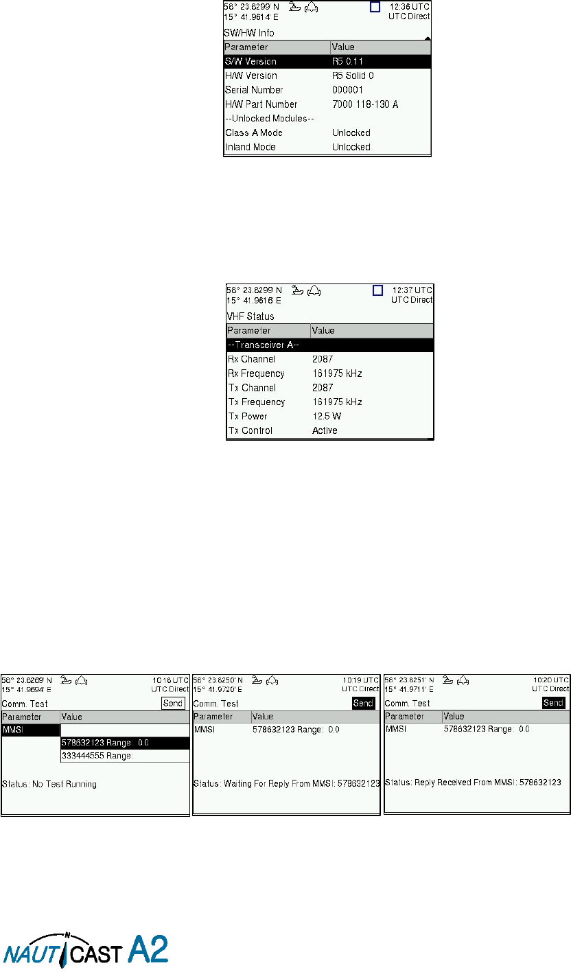
Page 39 of 80 1001001-2EN A2 Product Manual 2_0
4.23 SW/HW Info
This view displays the software and hardware revisions for the NAUTICAST A2 and is accessed from Main
Menu Status SW/HW Info
.
NOTE: This information should always be provided when in contact
with Nauticast Technical Support.
Figure 31 - SW/HW Info
4.24 VHF Status
The VHF Status view shows the currently used settings. Channel number, frequency, power and operation
mode are displayed for each VHF transceiver in the NAUTICAST A2. This information is useful when
troubleshooting to make sure that the NAUTICAST A2 transponder uses the expected VHF radio settings. If
e.g. a regional area is set and in use, this will affect the parameters in the VHF Status view.
Figure 32 - VHF Status
4.25 Communication Test
When installing the NAUTICAST A2, or when performing annual testing, a communication test shall be done
to ensure that other transponder system can receive the NAUTICAST A2 transmissions. This can be done from
the Communication Test view accessed from
Main Menu Maintenance Comm. Test
.
When entering the Communication Test view a suggested target with a suitable range (between 15 NM and
25 NM) will be selected in the MMSI parameter field if such a target has been received by the NAUTICAST A2.
It is however possible to select a different target for the communication test. To start the test, use the ARROW
KEYPAD button ∧ to select the “Send” button and press ENTER. The status of the test will be shown beneath
the parameter list. If no response is received within 15 seconds from the selected target a fail message will
be shown.
Figure 33 - Communication Test
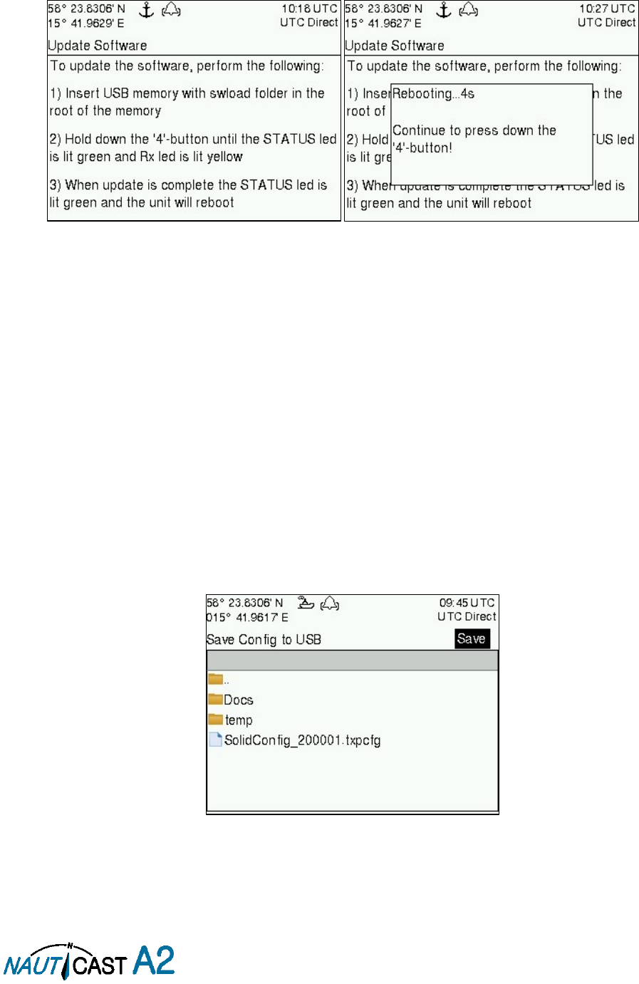
Page 40 of 80 1001001-2EN A2 Product Manual 2_0
4.26 Update Software
The software in the NAUTICAST A2 is easy upgradable via the USB Host interface located behind the front
hatch. To perform a software update, follow the instructions in the
Update Software
view which can be
accessed from
Main
MenuMaintenanceUpdate Software
. For more information about the upgrade
procedure, refer to chapter 5 “
Figure 34 - Update Software
4.27 Restore Config
All config parameters described in section 4.4 “Configuration Parameters” can be set to default values from
the
Restore Config
view which can be accessed from
Main Menu Maintenance Restore Config
.
NOTE: The MMSI parameter will also be reset to zero and therefore the transponder will stop
transmitting and the alarm “Tx Malfunction” will become active.
4.28 Save Configuration to USB memory
The NAUTICAST A2 AIS Transponder System has the capability to save all configuration settings to an USB
memory. The configuration file can be used as backup so that the NAUTICAST A2 AIS system can be restored
to a previous configuration; however during normal software upgrade of the NAUTICAST A2 AIS system the
configuration parameters will NOT be changed so a backup is usually not needed.
The saved configuration file can also be used to load several NAUTICAST A2 systems with the same settings.
To save the configuration to a file on a USB memory, follow the steps below:
1. Insert a FAT32 formatted USB memory in the USB host interface port in the NAUTICAST A2.
2. Enter the
Save Config to USB
view which is accessed from
Main Menu Maintenance Save Config
to USB
.
Figure 35 – Save Config to USB
3.
Open
the folder on the USB memory where the transponder configuration file should be saved.
Use the arrow keypad to navigate between folders and files on the USB memory. Only folders and
transponder configuration files will be listed in the view. To view the contents of a sub folder, mark
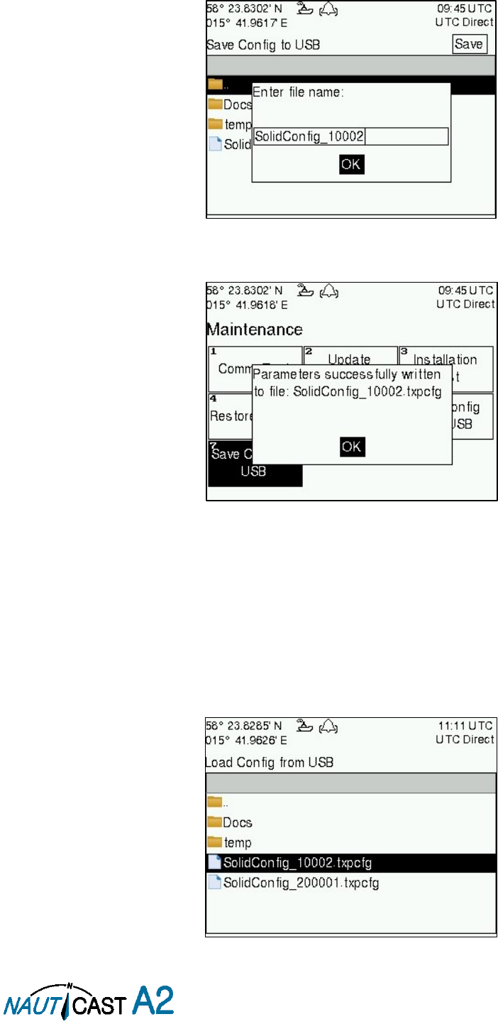
Page 41 of 80 1001001-2EN A2 Product Manual 2_0
the folder and press ENTER. To go back to the previous folder, mark the folder “..” on the top of the
list and press ENTER.
4. Press the “Save” button. A popup will appear where a file name can be entered.
Figure 36 – Enter file name
5. Press OK to save the configuration to the specified file and directory on the USB
Figure 37 – Configuration Saved Successfully.
4.29 Load Configuration from USB memory
To load and directly use a configuration from an existing configuration file on a USB memory, follow the below
steps:
1. Insert the USB memory with the configuration file in the USB host interface port on the NAUTICAST
A2.
2. Enter the
Load Config from USB
view which is accessed from
Main Menu Maintenance Load
Config from USB
.
Figure 38 – Load Config from USB
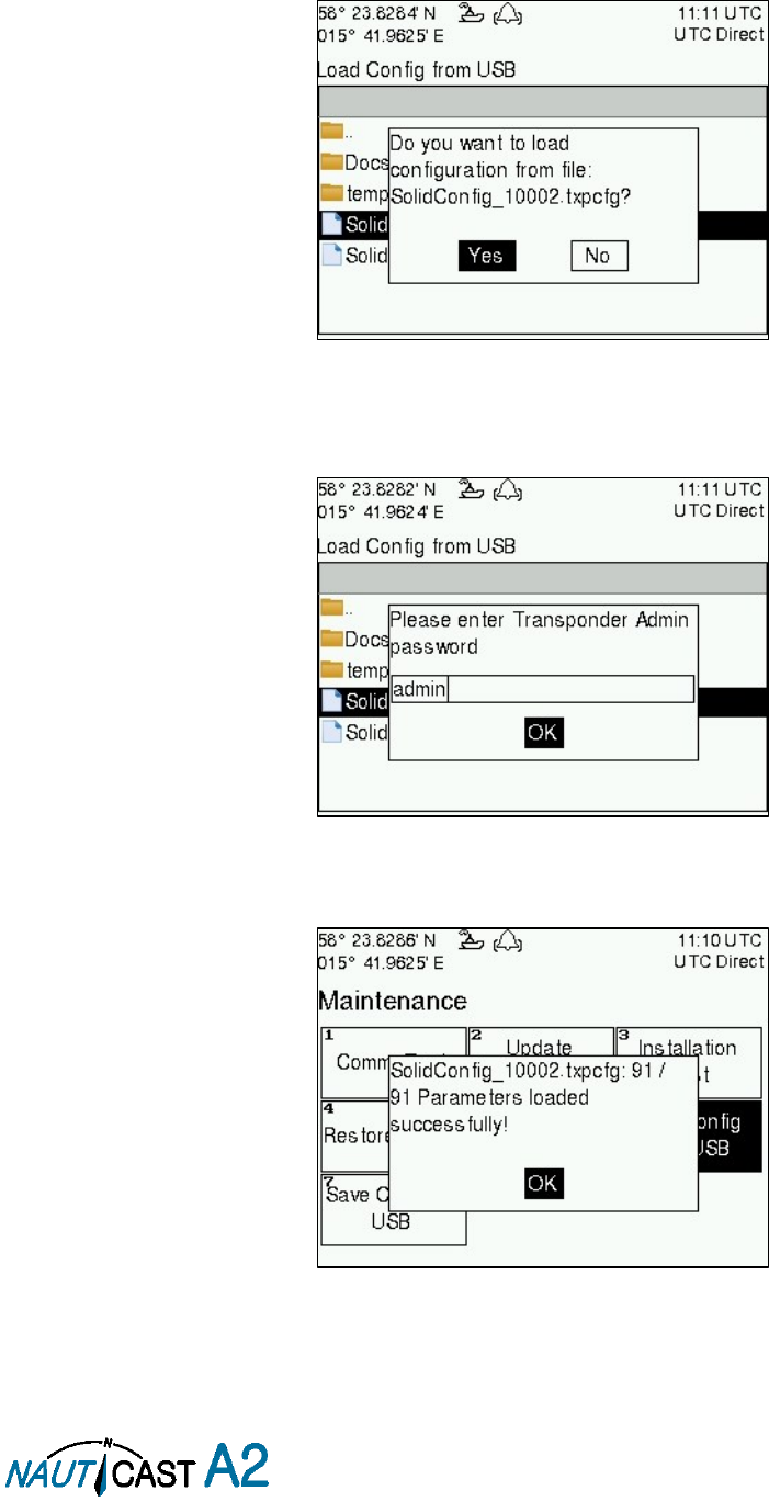
Page 42 of 80 1001001-2EN A2 Product Manual 2_0
3. Select the desired configuration file.
Use the arrow keypad to navigate between folders and files on the USB memory. Only folders and
transponder configuration files will be listed in the view. To view the contents of a sub folder, mark
the folder and press ENTER. To go back to the previous folder, mark the folder “..” on the top of the
list and press ENTER.
4. Press ENTER to load the selected file. A confirmation popup will appear.
Figure 39 – Confirmation popup
5. Check that the correct configuration file is selected. Press “Yes” in the confirmation popup. A password
popup will appear. Fill in the admin password (default = “admin”) and press OK.
Figure 40 – Password popup
6. The configuration file will be loaded in the NAUTICAST A2 and the settings will take effect immediately.
Figure 41 – Configuration successfully loaded from USB

Page 43 of 80 1001001-2EN A2 Product Manual 2_0
5 Software Upgrade
Note: After updating the software add a sticker stating the new software version close to the
product label.
The NAUTICAST A2 is easy upgradable through the USB host interface located behind the front hatch. To
upgrade the software in the NAUTICAST A2, perform the following steps:
Unzip the NAUTICAST A2 upgrade package in the root folder of an USB memory stick. There should
now be a folder called swload in the USB root folder.
Insert the USB memory stick in the USB host interface located behind the front hatch.
Hold down the ‘4’-button on the front of the NAUTICAST A2 and reboot the system. The ‘4’-button must be
held down until the STATUS LED is lit green and Rx LED is lit yellow.
The software upgrade is complete when the STATUS LED is lit green. The NAUTICAST A2 will automatically
reboot after 3 seconds. Check that correct SW has been loaded in the SW/HW Info view which can be accessed
through
Main Menu Status SW/HW Info
.
If the upgrade process fails, The STATUS LED will be lit red and one of the Rx LED or Tx LED starts blinking.
Should this happen, hold down the ‘4’-button and reboot the NAUTICAST A2 to try again.
The software upgrade can also be initiated from the
Update Software
view in the NAUTICAST A2. Refer to
section 4.26 “Update Software” for more information.
STATUS
Rx
Tx
Upgrade mode started
GREEN
YELLOW
Upgrade in progress
Blinking YELLOW
Upgrade complete (automatic
reboot after 3 sec)
GREEN
Error: USB Not Found
RED
Blinking YELLOW
0.5Hz
Error: No SW found on USB
RED
Blinking YELLOW 4Hz
Error: Flash erase failed
RED
Blinking RED
0.5 Hz
Error: Flash write failed
RED
Blinking RED
4 Hz
Table 11 – LED Indicators during Software Upgrade

Page 44 of 80 1001001-2EN A2 Product Manual 2_0
6 Technical Specifications
6.1 Transponder Physical
Dimensions:
Height: 87 mm
Width: 238 mm
Depth: 173 mm
Dimensions:
Incl. gimbal mount
Height: 124 mm (minimum)
Width: 292 mm
Depth: 173 mm
Weight:
2.25 kg
2.45 kg incl gimbal mount
6.2 Transponder Electrical
Supply Voltage:
24 VDC (12VDC)
Power Consumption (/Max):
17W/24W (48W)
Peak Current
1 A (4A)
6.3 Transponder Environment
This product complies with the R&TTE directive, 1999/5/EC
Temperature:
-15˚C to +55˚C (Operational)
-30˚C to +80˚C (Storage)
Vibrations:
IEC 60945 ed. 4
EMC:
IEC 60945 ed. 4
Radio Type Approval:
IEC 61993-2 ed. 2
Compass Safe Distance
NAUTICAST A2
60 cm (for standard magnetic compass)
45 cm (for steering magnetic compass)
Compass Safe Distance
GPS Antenna AT575-68W
30 cm (for standard magnetic compass)
30 cm (for steering magnetic compass)
Compass Safe Distance
GPS Antenna MA-700
65 cm (for standard magnetic compass)
50 cm (for steering magnetic compass)
Compass Safe Distance
Combined VHF/GPS-1
65 cm (for standard magnetic compass)
50 cm (for steering magnetic compass)
6.4 Transponder VHF Transceiver
Receivers:
156 – 163 MHz (TDMA)
156.525 MHz fixed (DSC, Channel 70)
Transmitter:
156 – 163 MHz
Channel bandwidth:
25 kHz
Output Power:
High: 12,5 W
Low: 1W
“Tanker 1W Mode”: 1W
VHF antenna connector:
BNC-Female
Antenna Input Impedance:
50 ohm
6.5 Transponder Internal GPS Receiver
Type:
GPS L1, C/A Code, 50 Channels
SBAS: WAAS, EGNOS, MSAS, GAGAN
Update rate:
2 Hz
Accuracy:
< 2.5 m (GPS, CEP, 50%, 24 hours static)
< 2.0 m (SBAS, CEP, 50% 24 hours static)
Antenna feeding:
5 VDC
GPS Antenna connector:
TNC-Female
Antenna Input Impedance:
50 ohm
6.6 AIS Alarm Relay
Max switching current:
0,1 – 2 A (with heat sink up to 3A)
Max switching voltage:
3 – 60 VDC

Page 45 of 80 1001001-2EN A2 Product Manual 2_0
7 Troubleshooting
The Nauticast A2 is a very rugged and stable device, so that in the majority of cases erroneous configurations
rather than real hardware defects are the cause of perceived malfunctioning.
7.1 Troubleshooting Prerequisites
A transponder operating environment may naturally affect and render complicated the search for the root
cause of a system defect. It is always advisable to start by minimizing all possible interference sources in order
to simplify the troubleshooting.
Disconnect other NMEA equipment from the NAUTICAST A2 (ECDIS, RADAR, NAV, etc.)
Switch off other emission sources (RADAR, SATCOM, VHF, etc.)
We encourage applying the latest software available for the NAUTICAST A2 if any problems are experienced.
It may contain bug-fixes and other improvements solving already known issues. Check supplied software
release notes to see what has been changed in the new software.
7.2 Troubleshooting with the Front Panel LED’s
It is very fast and effective to use the LED’s to verify the status of the NAUTICAST A2. This should always be
the first step in the troubleshooting.
7.2.1 STATUS LED (multi-colour)
The STATUS LED is constantly lit green when the transponder is operating and no alarms are active.
The STATUS LED is constantly lit red if there is one or more acknowledged active alarms in the
transponder, but no unacknowledged alarms. Refer to section 7.3 for interpretation of the alarms.
The STATUS LED is flashing red if there is one or more unacknowledged alarms in the transponder.
Refer to section 7.3 for interpretation of the alarms.
If neither colours are lit, nor flashing, then check the power supply and make sure that:
The voltage is correct and stable
The polarity is correct and not switched
The available current is sufficient for start up and transmission
The external fuse is functional
The power cable is undamaged
The power connector is properly connected and secured
Also check so that the LED backlight is not completely turned off in the Visual Config view accessed from
Main
MenuConfigDisplayVisual
.
7.2.2 Rx LED (yellow)
The Rx LED is flashing yellow when the transponder is receiving a message from the VDL. This can be
intermittently.
If there is verified traffic on the VDL and the Rx LED still is dark, then check the alarm list for any active
alarms. Refer to section 7.3 for interpretation of the alarms.
Lack of reception may be an indication of a VHF antenna problem or connectivity issues. Check the installation
for problems.
7.2.3 Tx LED (red)
The Tx LED is flashing red when the transponder is transmitting a message to the VDL. The transmission
interval is between 2 – 360 seconds. Refer to section 7.5.
If the Tx LED is completely dark, then check so that the transmission is not switched off either through an
active regional area or by the Tx Mode parameter. It is possible to check the status on each transceiver in the
VHF Status view described in section 4.24.
If the transmission is activated and there is still no red flashing, then check the alarm list for any active alarms.
Refer to section 7.3 for interpretation of the alarms.
7.3 Troubleshooting with Alarm Messages
The NAUTICAST A2 constantly monitors itself for failures, abnormal conditions and other important
parameters. Some of the monitoring trigger alarms and those alarms are excellent aids in the troubleshooting
process. An active alarm can have two states, unacknowledged or acknowledged. The state of an alarm will
affect the STATUS LED. Refer to section 7.2.1.

Page 46 of 80 1001001-2EN A2 Product Manual 2_0
A new alarm (unacknowledged) will raise a pop-up window that needs to be acknowledged by the user. The
active alarms can be found in the alarm view. Refer to section 4.18.
All active alarms are outputted on all the serial interface ports every 30 seconds. The alarm status can for
example be used in interfacing ECDIS systems or centralized alarm systems. The alarms can also be monitored
or recorded for troubleshooting purposes by for example a terminal application.
The status of an alarm can be identified by two letters in the alarm sentence, “A” and “V”. The alarm
sentence is constructed as:
$AIALR,hhmmss.ss,xxx,A,A,c-c, where:
hhmmss.ss = Time (UTC) of alarm condition change
xxx = Unique alarm identifier
A = Alarm condition (A = Active, V = Inactive)
A = Alarm’s acknowledge state, A = acknowledged, V = unacknowledged
c-c = Alarm’s description text
$AIALR,hhmmss.ss,xxx,V,A,c-c: Tx malfunction
: Alarm is Inactive
$AIALR,hhmmss.ss,xxx,V,V,c-c: Tx malfunction
: Alarm is Inactive
$AIALR,hhmmss.ss,xxx,A,A,c-c: Tx malfunction
: Alarm is Active and Acknowledged
$AIALR,hhmmss.ss,xxx,A,V,c-c: Tx malfunction
: Alarm is Active and Unacknowledged
The alarms that can occur in the NAUTICAST A2 are listed below:
7.3.1 AIS: Tx Malfunction (ID 001)
A Tx Malfunction alarm is generated if there is a malfunction in the radio transmitter hardware or if the antenna
VSWR exceeds an allowed ratio. If the radio transmitter returns to normal operation or if VSWR returns to a
value below the allowed threshold, the alarm is cleared. The Tx Malfunction alarm is also generated when the
MMSI is configured to “0”, in which case the NAUTICAST A2 will not transmit.
7.3.2 AIS: Antenna VSWR Exceeds limit (ID 002)
The VSWR (Voltage Standing Wave Ratio) of the antenna is checked for every transmission and if it exceeds
a given ratio then a VSWR alarm is generated. If the VSWR goes below the allowed threshold, the alarm is
cleared.
7.3.3 AIS: Rx Ch A Malfunction (ID 003)
7.3.4 AIS: Rx Ch B Malfunction (ID 004)
7.3.5 AIS: Rx Ch C Malfunction (ID 005)
The radio receivers are continuously monitored and if any part of the receivers’ hardware should malfunction,
an Rx Malfunction alarm is generated for that receiver. If the radio receiver returns to normal operation, the
alarm is cleared.
7.3.6 AIS: General Failure (ID 006)
This alarm is generated if the NAUTICAST A2 fails to initiate the radio or if a severe hardware failure has
occurred. If this alarm occurs, contact your retailer.
7.3.7 AIS: UTC Sync Invalid (ID 007)
This alarm is generated when the NAUTICAST A2 loses UTC direct synchronization (cannot synchronize from
internal GPS receiver).
7.3.8 AIS: MKD connection lost (ID 008)
This alarm is active if the communication between the control unit and the display unit in the NAUTICAST A2
does not work.
7.3.9 AIS: Internal/External GNSS position mismatch (ID 009)
This alarm is generated if the difference between the internal and external GNSS position is more than 100 m
for more than 15 minutes.
7.3.10 AIS: NavStatus incorrect (ID 010)
This alarm is generated if the navigational status is incorrect. If e.g. the navigational status is set to “At
Anchor” but the ship is moving faster than 3 knots, the NavStatus incorrect alarm will become active.
7.3.11 AIS: Heading sensor offset (ID 011)
This alarm is active when SOG (Speed Over Ground) is greater than 5 kn and the difference between COG
(Course Over Ground) and HDT (True Heading) is greater than 45˚ for 5 min.
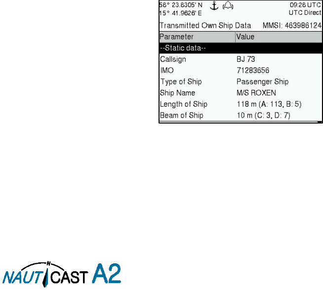
Page 47 of 80 1001001-2EN A2 Product Manual 2_0
7.3.12 AIS: Active AIS SART (ID 014)
This alarm is generated when the NAUTICAST A2 has received an active AIS SART position report.
7.3.13 AIS: External EPFS Lost (ID 025)
This alarm is generated if the position from the external Electronic Position Fixing System is invalid (i.e. no
external GNSS). Due to the fallback arrangement for the positioning sensor this alarm can be inactive up to
30 seconds (during which the internal GNSS is used) before the alarm is activated.
7.3.14 AIS: No Sensor Position In Use (ID 026)
This alarm is active if the NAUTICAST A2 does not have a valid position (latitude/longitude) from any sensor.
7.3.15 AIS: No Valid SOG Information (ID 029) / No Valid COG Information (ID 030)
These alarms are active if the NAUTICAST A2 does not have a valid SOG (Speed Over Ground) or a valid COG
(Course Over Ground) from any sensor. The SOG and COG is based on the speed log (if external GNSS is used
and a valid heading is available) or the GNSS currently in use.
7.3.16 AIS: Heading Lost/Invalid (ID 032)
This alarm is generated if either the heading information is lost/invalid (from external sensors) or if the heading
is undefined.
7.3.17 AIS: No Valid ROT Information (ID 035)
This alarm is active if ROT (Rate of Turn) is undefined or if no valid ROT information is available from external
sensor or internal calculations.
7.3.18 IAIS: Ship Size mismatch (ID 060)
This alarm is active when the inland parameters length and beam of ship does not match the antenna position
parameters A, B, C and D.
7.3.19 AIS: Tx disabled externally (ID 072)
This alarm is active when an external silent switch is used and the switch has disabled transmissions.
7.4 Troubleshooting via the Display
There is a lot of information and data accessible via the display that can be useful for troubleshooting, and
that can help finding a presumed problem. The following items are just a few examples of what to look at.
7.4.1 Transmitted Own Ship Data View
When the transponder transmits data on the VDL, it also simultaneously outputs this data on all the serial
ports. This information is displayed in the Transmitted Own Ship Data view.
Figure 42 – Transmitted Own Ship Data
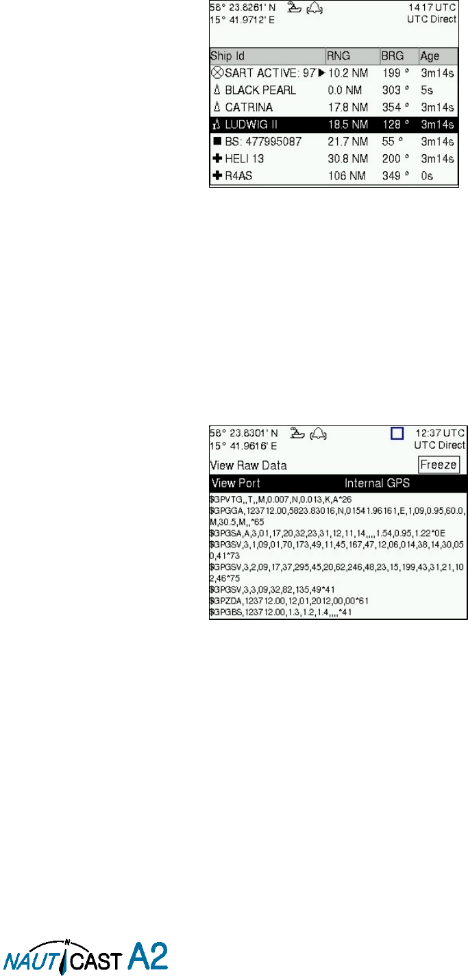
Page 48 of 80 1001001-2EN A2 Product Manual 2_0
7.4.2 Target List
The target list is primarily useful when analyzing the receiving functionality. The propagation characteristics
of VHF radio frequencies are close to line of sight. A harsh radio environment, reflections in cables, connectors
or the antenna will shorten the effective range.
Figure 43 – Target List
7.4.3 Date and Time
The date and time (UTC) in the upper right corner of the display is provided by the transponder. If the date
and time are not correct, the transponders internal GPS does not have a position fix. This will also be indicated
by the alarm “UTC sync invalid”. This problem is normally caused by a GPS-antenna failure or damaged
antenna cables. This problem may also be caused by interference from radio equipment on-board.
7.4.4 View Raw Data
The
View Raw Data
view can be used to see received data on the ports of the NAUTICAST A2. It is useful for
troubleshooting to make sure that connected sensors provide correct data to the NAUTICAST A2 unit. The
“View Port” parameter determines from which port the data displayed in the view are taken. It is possible to
pause the view by pressing the “Freeze” button. All data that is received while the view is paused will not be
displayed in the view.
Figure 44 – View Raw Data
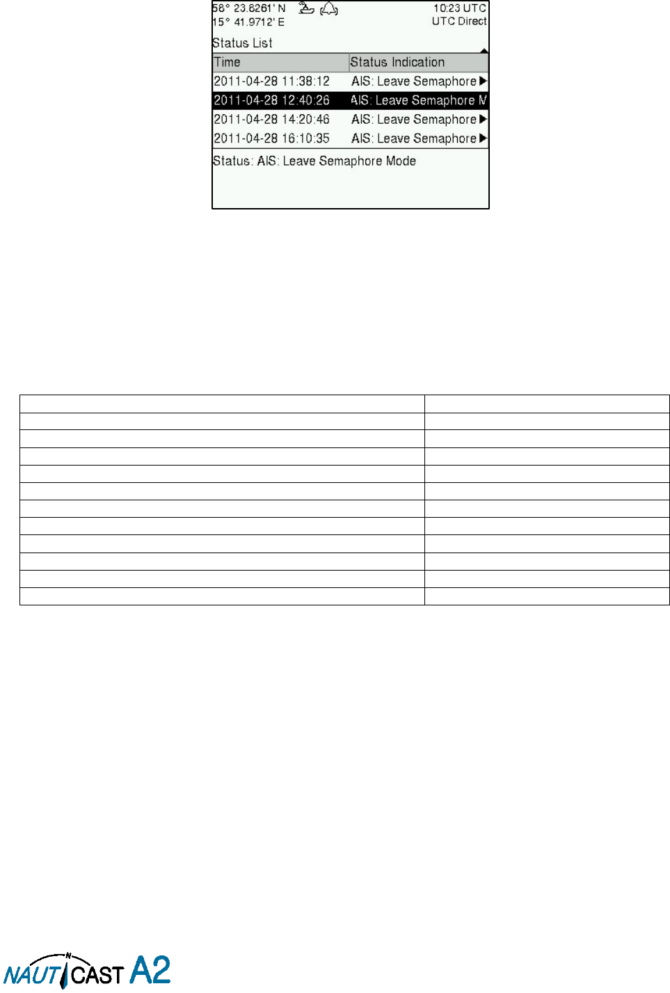
Page 49 of 80 1001001-2EN A2 Product Manual 2_0
7.4.5 Status List
The status list view is used to display status indications that are stored in the transponder. The indications are
created when an important event has occurred in the transponder. Time of occurrence and status indication
text are shown in the view. A list of all possible indications can be found in section 7.8 Indication Messages.
Figure 45 – Status List
7.5 Reporting Intervals for Class A Transponders
The different information types are valid for different time periods and therefore they need different update
intervals. These update intervals are defined in the AIS standard (ITU-R M.1371) and should be applied by all
transponders. There are however some exceptions from this, which can be found in the standard. Class B
transponders have for example different intervals than the Class A transponder.
All this needs to be taken in consideration while troubleshooting thus it affects the anticipated behaviour of a
transponder.
Information type / Condition
Nominal reporting interval
Static Information
6 min, on amendment, on request
Voyage related information
6 min, on amendment, on request
Dynamic information (See conditions below)
- Ship at anchor or moored and not moving faster than 3 knots
3 minutes
- Ship at anchor or moored and moving faster than 3 knots
10 seconds
- Ship 0-14 knots
10 seconds
- Ship 0-14 knots and changing course
3 1/3 seconds
- Ship 14-23 knots
6 seconds
- Ship 14-23 knots and changing course
2 seconds
- Ship > 23 knots
2 seconds
- Ship > 23 knots and changing course
2 seconds
Table 12 – Reporting Intervals

Page 50 of 80 1001001-2EN A2 Product Manual 2_0
7.6 F.A.Q
7.6.1 I cannot see the vessel on the Internet AIS service
Websites providing AIS services like e.g. www.marinetraffic.com does not cover all the seas of the world, but
only specific coastal areas where AIS receivers have been installed and that upload the data to the websites.
The vessel must be in reception range of these AIS receivers to show up on the Internet AIS service. If wrong
information about your ship shows up on these websites (e.g. pictures or wrong position), this doesn’t mean
your AIS is not working correctly. If the data is shown correctly on the AIS, the incorrect information is mostly
due to false information delivered to these websites through other sources.
7.6.2 I can “see” the other vessel, but they do not “see” my vessel
There are several reasons why this might happen. The first thing to check is if the NAUTICAST A2 is
transmitting at all or if is transmitting in low power mode. In
VHF Status
view described in section 4.24 it is
possible to check the status on all NAUTICAST A2 VHF transceivers. Make sure that correct channels and
power mode are used. There might be a regional area set in the transponder that changes the operating mode
of the NAUTICAST A2. Regional areas are listed in the
Regional Area
view (see section 4.17).
The MMSI must also be configured in order for the NAUTICAST A2 to transmit. If the MMSI is zero, the
NAUTICAST A2 will be silent.
Another possibility is that the other vessels’ transponder requires a shorter reception range in order to receive
the NAUTICAST A2 transmissions. In the
Target List
view and the
Plot
view it is possible to see the range and
bearing to other vessels.
7.6.3 The VHF range seems to be short
As a general rule, the VHF range is equal to line of sight from the antenna position, which means that the
higher the antenna is installed, the longer the range will be. It is also important to follow the guide lines for
an antenna installation thoroughly. Section 3.4 describes how to best install the VHF antenna.
7.6.4 I can only receive a few GPS satellites
The position of the GPS antenna is of high importance to optimize the GPS reception. Follow the guide lines
of GPS antenna installation described in section 3.5.
If the ship is close to a harbour or shore with high structures or travelling in an area with high terrain, the GPS
reception might be lowered. The GPS antenna must be installed where it has a clear view of the sky. The
objective is to see the horizon freely through 360 degrees with a vertical observation of 5 to 90 degrees above
the horizon.
The GPS antenna cable should also be as short as possible and with 50 Ω impedance. A very long antenna
cable or faulty impedance can heavily reduce the GPS reception.
7.7 Contact & Support information
Contact your local dealer for NAUTICAST A2 support. Please visit www.nauticast.com to see our worldwide
service partners.
Nauticast GmbH
Lützowgasse 12-14/ 3. OG
1140 Vienna
Austria
Tel: +43 (1) 5 237 237-240
Fax: +43 (1) 5 237 237-150
Mail: support@nauticast.com
Web: www.nauticast.com
To enable us to provide you with precise and thorough support please contact support@nauticast.com per
Email and include the “Technical Support / Problem Report using all relevant information provided by the
SW/HW Info view which can be accessed from
Main MenuStatusSW/HW Info
.

Page 51 of 80 1001001-2EN A2 Product Manual 2_0
7.8 Indication Messages
The indication messages, with identity and type information, are listed below:
ID
Type
Message text
021
Status
External DGNSS in use
022
Status
External GNSS in use
023
Status
Internal DGNSS in use (beacon)
024
Status
Internal DGNSS in use (msg 17)
025
Status
Internal GNSS in use
027
Status
External SOG/COG in use
028
Status
Internal SOG/COG in use
031
Status
Heading valid
033
Status
Rate of Turn Indicator in use
034
Status
Other ROT source in use
036
Event
Channel management parameters changed
056
Event
Channel management zone memory changed
061
Status
Enter semaphore mode
062
Event
Leave semaphore mode
063
Event
NVM Checksum errors
064
Event
RATDMA overflow
066
Status
Tanker Low VHF Power Mode
067
Status
Beacon correction received
068
Status
VDL correction received (id XXXX)
069
Status
No correction received
7.9 Long Range Definitions
A = Ship’s name, call sign, and IMO number
B = Date and time of message composition
C = Position
E = Course over ground (COG)
F = Speed over ground (SOG)
I = Destination and Estimated Time of Arrival (ETA)
O = Draught
P = Ship/Cargo
U = Ship’s length, breadth, type
W= Persons on board

Page 52 of 80 1001001-2EN A2 Product Manual 2_0
8 Interpretation of Input Sentences
All interface ports accepts the full set of input listed below sentences, except the sentences listed in section
8.4.1
that are unique to the Long Range interface port.
The protocol of the serial input sentences shall be compliant to IEC 61162-1Ed.4 (2010-11) for maximum
interoperability.
8.1 GPS and Sensor Input Sentences
8.1.1 DTM - Datum Reference
If local code is other than WGS84, then the positions report from that port is discarded.
$--DTM,ccc,a,x.x,a,x.x,a,x.x,ccc
Field
Format
Name
Comment
1
--DTM
Sentence Id
Used
2
ccc
Local Datum Code
Interpret if it’s WGS84 or not
3
A
Local Datum Subdivision Code
Ignored
4
x.x
Lat Offset (2 fields)
Ignored
Ignored
5
a
6
x.x
Long Offset (2 fields)
Ignored
Ignored
7
a
8
x.x
Altitude Offset
Ignored
9
ccc
Reference Datum Code
Ignored
8.1.2 GBS - GNSS Satellite Fault Detection
If this sentence is received once a second from the position source in use, the RAIM flag will be set to TRUE.
$--GBS,hhmmss.ss,x.x,x.x,x.x,xx,x.x,x.x,x.x
Field
Format
Name
Comment
1
--GBS
Sentence Id
Used
2
hhmmss.s
s
UTC Time of GGA or GNS
Ignored
3
x.x
Expected Error in latitude
Used
4
x.x
Expected Error in longitude
Used
5
x.x
Expected error in altitude
Ignored
6
xx
ID number of most likely failed satellite
Ignored
7
x.x
Probability of missed detection
Ignored
8
x.x
Estimate of bias in meters
Ignored
9
x.x
Standard Deviation of bias estimate
Ignored
8.1.3 GGA - Global Positioning System Fix Data
$--GGA,hhmmss.ss,llll.ll,a,yyyy.yy,a,x,xx,x.x,x.x,M,x.x,M,x.x,xxxx
Field
Format
Name
Comment
1
--GGA
Sentence Id
Used
2
hhmmss.s
s
UTC of position
UTC Second is used to indicate Time
Stamp
3
llll.ll
Latitude
Used
4
a
5
yyyy.yy
Longitude
Used
6
a
7
x
GPS quality indicator
Used,
1 -> Position with Low Accuracy
2 -> Position with High Accuracy
3 -> Position with Low Accuracy
6 -> Dead Reckoning with Low Accuracy
7 -> Manual mode with low accuracy
OTHER -> No Position
Used when the GPS is the internal GPS
(Used in proprietary sentences)
8
xx
Satellites in use
Ignored
9
x.x
Horizontal dilution of precision
Ignored
10
x.x
Antenna altitude
Ignored
11
M
Units of antenna altitude, meter
Ignored
12
x.x
Geodial separation
Ignored
13
M
Units of geodial sep.
Ignored
14
x.x
Age of differential GPS data
Ignored
15
xxxx
Differential reference station ID
Ignored
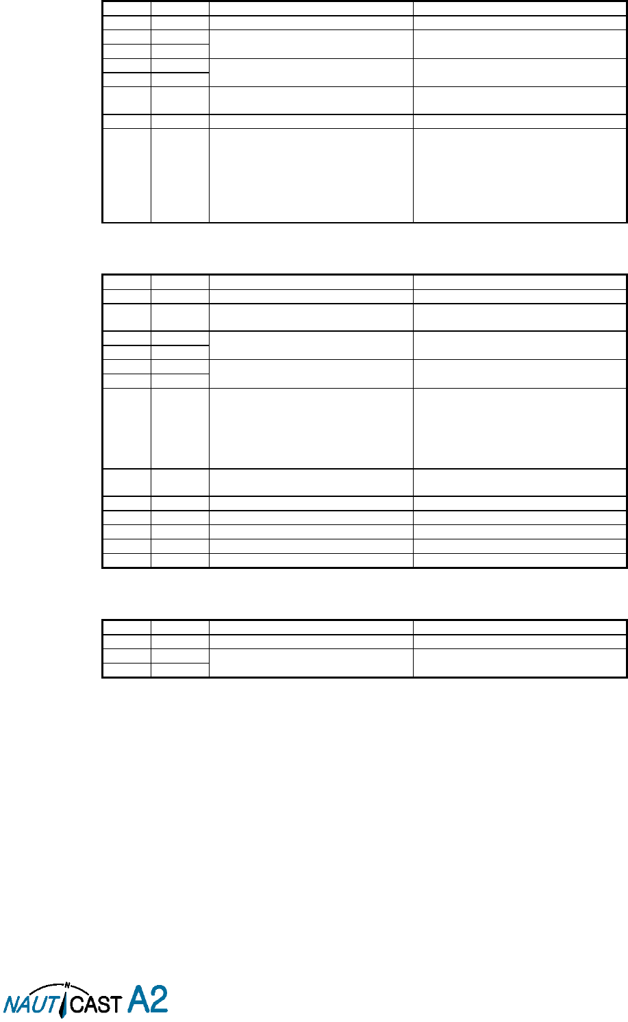
Page 53 of 80 1001001-2EN A2 Product Manual 2_0
8.1.4 GLL – Geographic position, latitude/longitude
$--GLL,llll.ll,a,yyyy.yy,a,hhmmss.ss,A,a
Field
Format
Name
Comment
1
--GLL
Sentence Id
Used
2
llll.ll
Latitude
Used
3
a
4
yyyy.yy
Longitude
Used
5
a
6
hhmmss.s
s
UTC of position
UTC Second is used to indicate Time
Stamp
7
A
Status
Used
8
a
Mode indicator
NULL -> Message is ignored
A -> Position with Low Accuracy
D -> Position with High Accuracy
E -> Dead Reckoning Mode with Low
Accuracy
M-> Manual Mode with Low Accuracy
OTHER -> No Position
8.1.5 GNS – GNSS fix data
If the Mode Indicator is a NULL field, the sentence is ignored.
$--GNS,hhmmss.ss,llll.ll,a,yyyy.yy,a,c--c,xx,x.x,x.x,x.x,x.x,x.x
Field
Format
Name
Comment
1
--GLL
Sentence Id
Used
2
hhmmss.s
s
UTC of position
UTC Second is used to indicate Time
Stamp
3
llll.ll
Latitude
Used
4
a
5
yyyy.yy
Longitude
Used
6
a
7
c--c
Mode indicator
A, P -> Position with low accuracy
D, R, F -> Position with high Accuracy
E -> Dead Reckoning Mode with Low
accuracy
M -> Manual Mode with low accuracy
OTHER -> No Position
8
xx
Total number of satellites
Used when the GPS source is the internal
GPS (used in proprietary sentences)
9
x.x
HDOP
Ignored
10
x.x
Antenna altitude, meter
Ignored
11
x.x
Geodial separation
Ignored
12
x.x
Age of differential corrections
Ignored
13
x.x
Differential reference station ID
Ignored
8.1.6 HDT - Heading, True
The use of this sentence is talker identifier dependent.
$--HDT,x.x,T
Field
Format
Name
Comment
1
--HDG
Sentence Id
Used
2
x.x
Heading, degrees true
Used
3
T
NOTE: HDT input must be sent at least every 3 seconds for the NAUTICAST A2 to calculate ROT
from the HDT input.

Page 54 of 80 1001001-2EN A2 Product Manual 2_0
8.1.7 OSD – Own ship data
$--OSD,x.x,A,x.x,a,x.x,a,x.x,x.x,a
Field
Format
Name
Comment
1
--OSD
Sentence Id
Used
2
x.x
Heading, degrees true
Used if heading status is ‘A’
3
A
Heading status
Used
4
x.x
Vessel course, degrees true
Used as COG
5
a
Course reference
Used1
6
x.x
Vessel speed
Used as SOG
7
a
Speed reference
Used1
8
x.x
Vessel set
Ignored
9
x.x
Vessel drift
Ignored
10
a
Speed units
Used to convert SOG to knots
8.1.8 RMC – Recommended minimum specific GNSS data
$--RMC,hhmmss.ss,A,llll.ll,a,yyyy.yy,a,x.x,x.x,xxxxxx,x.x,a,a
Field
Format
Name
Comment
1
--RMC
Sentence Id
Used
2
hhmmss.s
s
UTC of position
UTC Second is used to indicate Time
Stamp
3
A
Status
Used
4
llll.ll
Latitude
Used
5
a
6
yyyy.yy
Longitude
Used
7
a
8
x.x
Speed over ground, knots
Used
9
x.x
Course over ground, degrees true
Used
10
xxxxxx
Date
Ignored
11
x.x
Magnetic variation
Ignored
12
a
13
a
Mode indicator
NULL -> Message is ignored
A -> Position with low accuracy
D -> Position with high accuracy
E -> Dead Reckoning Mode with Low
accuracy
M -> Manual Mode with low accuracy
OTHER -> No Position
8.1.9 ROT – Rate of turn
The rate of turn value is only used if the talker identifier is TI. Otherwise the value will only be used to
determine the direction, i.e. ”Moving Right” or ”Moving Left”.
$--ROT,x.x,A
Field
Format
Name
Comment
1
--ROT
Sentence Id
Used
2
x.x
Rate of turn
Used if Status is set to ‘A’
3
A
Status
Used
8.1.10 VBW - Dual Ground / Water Speed
The current position source must be external GPS, and heading must be available for the transponder to accept
this sentence.
$--VBW,x.x,x.x,A,x.x,x.x,A,x.x,A,x.x,A
Field
Format
Name
Comment
1
--ROT
Sentence Id
Used
2
x.x
Longitudinal water speed
Ignored
3
x.x
Transverse water speed
Ignored
4
A
Status: water speed
Ignored
5
x.x
Longitudinal ground speed
Used if Status is set to A
6
x.x
Transverse ground speed
Used if Status is set to A
7
A
Status: ground speed
Used
8
x.x
Stern transverse water speed
Ignored
9
A
Status stern water speed
Ignored
10
x.x
Stern transverse ground speed
Ignored
11
A
Status stern ground speed
Ignored
1
SOG and COG are used if both COG reference and SOG reference are set to either: B, P, R
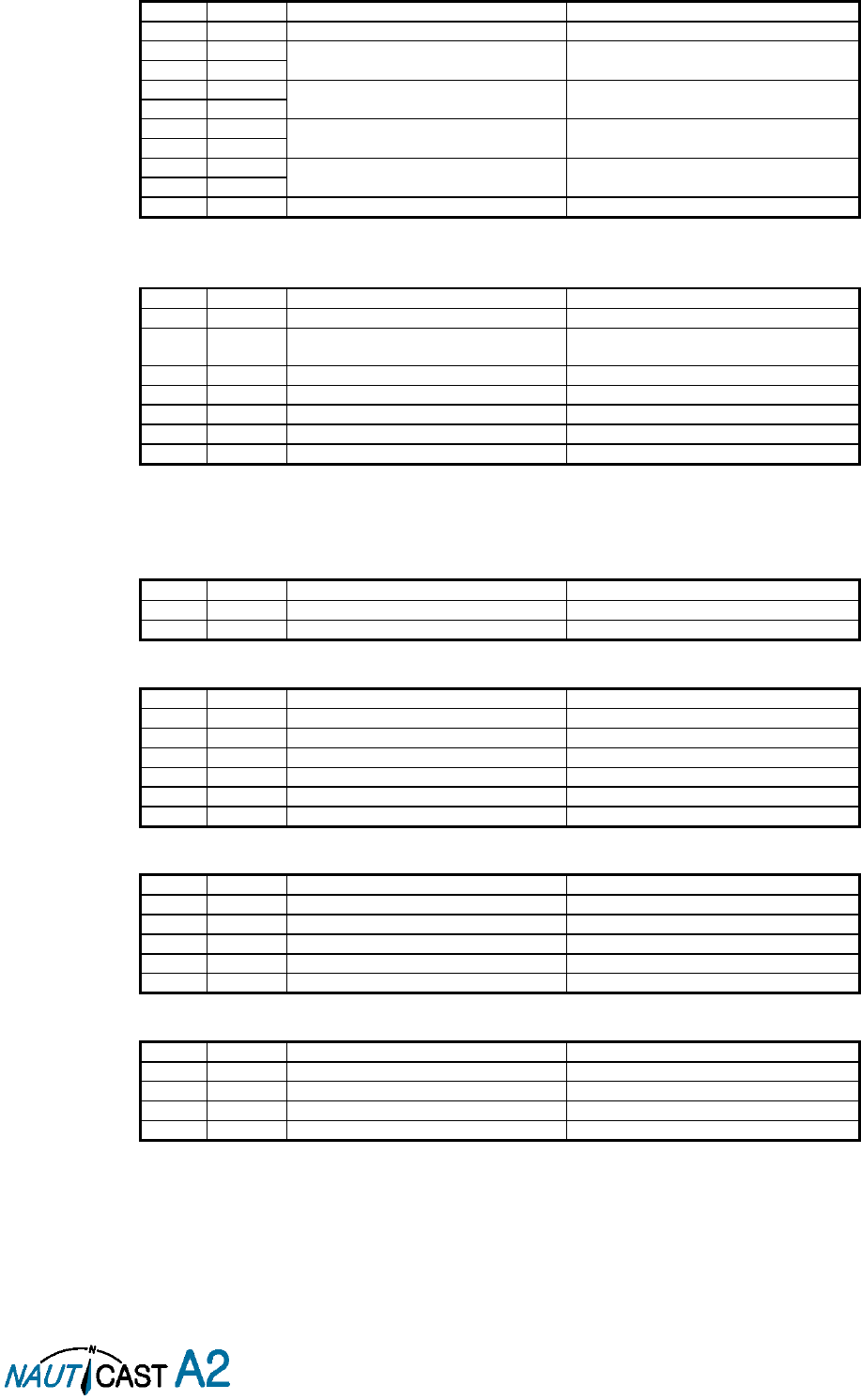
Page 55 of 80 1001001-2EN A2 Product Manual 2_0
8.1.11 VTG – Course over ground and ground speed
$--VTG,x.x,T,x.x,M,x.x,N,x.x,K,a
Field
Format
Name
Comment
1
--VTG
Sentence Id
Used
2
x.x
Course over ground, degrees true
Used
3
T
4
x.x
Course over ground, degrees magnetic
Ignored
5
M
6
x.x
Speed over ground, knots
Used
7
N
8
x.x
Speed over ground, km/h
Ignored
9
K
10
a
Mode indicator
Used
8.1.12 ZDA – Time and date
This message is only interpreted if it’s received from the internal GPS (the time synchronisation source).
$--ZDA,hhmmss.ss,xx,xx,xxxx,xx,xx
Field
Format
Name
Comment
1
--ZDA
Sentence Id
Used
2
hhmmss.s
s
UTC
Used
3
xx
Day (UTC)
Used
4
xx
Month (UTC)
Used
5
xxxx
Year (UTC)
Used
6
xx
Local zone hours
Ignored
7
xx
Local zone minutes
Ignored
8.2 General Input Sentences
8.2.1 ACK – Acknowledge Alarm
$--ACK,xxx
Field
Format
Name
Comment
1
--ACK
Sentence Id
Used
2
xxx
ID of the alarm source
Used
8.2.2 EPV – Command or report equipment property value
$--EPV,a,c--c,c--c,x.x,c--c,
Field
Format
Name
Comment
1
--EPV
Sentence Id
Used
2
a
Sentence status flag
Used
3
c--c
Destination equipment type
Used, AI or STT
4
c--c
Unique Identifier
Used, may be null
5
x.x
Property identifier
Used
6
c--c
Value of property to be set
Used
8.2.3 SPW – Security Password Sentence
$--SPW,ccc,c--c,x,c--c
Field
Format
Name
Comment
1
--SPW
Sentence Id
Used
2
ccc
Password protected sentece
Used
3
c--c
Unique Identifier
Used, may be NULL
4
x
Password level
Used
5
c--c
Password
Used
8.2.4 HBT – Heartbeat Supervision Sentence
$--HBT,x.x,A,x
Field
Format
Name
Comment
1
--SPW
Sentence Id
Used
2
x.x
Configured repeat interval
Used (Limited to 60 sec)
3
A
Equipment status
Used
4
x
Sequential sentence identifier
Ignored

Page 56 of 80 1001001-2EN A2 Product Manual 2_0
8.3 AIS Specific Input Sentences
8.3.1 ABM – Addressed Binary and Safety-Related Message
!--ABM,x,x,x,xxxxxxxxx,x,x.x,s--s,x
Field
Format
Name
Comment
1
--ABM
Sentence Id
Used
2
x
Total nr of sentences
Used if in interval 1..9, otherwise the
sentence is ignored
3
x
Sentence number
Used if in interval 1..total sentences,
otherwise the sentence is ignored
4
x
Sequential message identifier
Used if in interval 0..3, otherwise the
sentence is ignored
5
xxxxxxxx
xx
MMSI of Destination
Used
6
X
AIS Channel
Used
7
x.x
Message Id
Used if 6 or 12, otherwise the sentence is
ignored
8
s--s
Encapsulated Data
Used
9
x
Number of filled bits
Used
8.3.2 ACA – AIS Regional Channel Assignment Message
The zone created of this sentence must be accepted by the channel management rules (size of zone, distance
to own position, valid channel number etc). If the zone isn’t accepted, the zone will be ignored.
$--ACA,x,llll.ll,a,yyyy.yy,a,llll.ll,a,yyyy.yy,a,x,xxxx,x,xxxx,x,x,x,a,x,
hhmmss.ss
Field
Format
Name
Comment
1
--ACA
Sentence Id
Used
2
x
Sequence number
Ignored
3
llll.ll
NE latitude (2 fields)
Used
4
a
5
yyyy.yy
NE longitude (2 fields)
Used
6
a
7
llll.ll
SW latitude (2 fields)
Used
8
a
9
yyyy.yy
SW longitude (2 fields)
Used
10
a
11
x
Transitional zone size
Used
12
xxxx
Channel A
Used
13
x
Channel A bandwidth
Used
14
xxxx
Channel B
Used
15
x
Channel B bandwidth
Used
16
x
Tx/Rx mode
Used
17
x
Power level
Used
18
a
Information source
Ignored
19
x
In use flag
Ignored
20
hhmmss.s
s
Time of In use change
Ignored
8.3.3 AIQ – Query Sentence
$--AIQ,ccc
Field
Format
Name
Comment
1
--
Talker ID of requester
Used
2
AIQ
Talker ID for device
Used
3
ccc
Approved sentence formatter of data
being requested
It’s possible to query the following
sentences:
ACA, ALR, EPV, LRI, SSD, TRL, TXT and
VSD

Page 57 of 80 1001001-2EN A2 Product Manual 2_0
8.3.5 AIR – AIS Interrogation Request
This sentence can also be used to do a “UTC Request”.
$--AIR,xxxxxxxxx,x.x,x,x.x,x,xxxxxxxxx,x.x,x,x
Field
Format
Name
Comment
1
--AIR
Sentence Id
Used
2
xxxxxxxx
x
MMSI 1
Used
3
x.x
Message ID 1.1
Used
4
x
Message sub section
Ignored
5
x.x
Message ID 1.2
Used, may be NULL
6
x
Message sub section
Ignored
7
xxxxxxxx
x
MMSI 2
Used, may be NULL
8
x.x
Message ID 2.1
Used, may be NULL
9
x
Message sub section
Ignored
10
x
Channel
Used, may be NULL
8.3.6 BBM – Broadcast Binary Message
$--BBM,x,x,x,x,x.x,s--s,x
Field
Format
Name
Comment
1
--BBM
Sentence Id
Used
2
X
Total number of sentences
Used if in interval 1..9, otherwise rejected
3
X
Sentence number
Used if in interval 1..total number of
sentences, otherwise rejected.
4
X
Sequential message identifier
Used if in interval 0..9, otherwise rejected
5
X
AIS channel
Used
6
x.x
Message Id
Used if 8 or 14
7
s—s
Encapsulated data
Used
8
X
Number of filled bits
Used
8.3.7 SSD – Ship Static Data
$--SSD,c--c,c--c,xxx,xxx,xx,xx,c,aa
Field
Format
Name
Comment
1
--SSD
Sentence Id
Used
2
c--c
Call sign
Used, may be NULL
3
c--c
Name
Used, may be NULL
4
xxx
Pos ref A
Used to change position reference for the
position source in use. May be NULL.
5
xxx
Pos ref B
Used to change position reference for the
position source in use. May be NULL.
6
xx
Pos ref C
Used to change position reference for the
position source in use. May be NULL.
7
xx
Pos ref D
Used to change position reference for the
position source in use. May be NULL.
8
c
DTE
Ignored
9
aa
Source identifier
Used
8.3.8 VSD – Voyage Static Data
$--VSD,x.x,x.x,x.x,c--c,hhmmss.ss,xx,xx,x.x,x.x
Field
Format
Name
Comment
1
--VSD
Sentence Id
Used
2
x.x
Type of ship and cargo
Used
3
x.x
Maximum present draught
Used
4
x.x
Persons on-board
Used
5
c--c
Destination
Used
6
hhmmss.s
s
Est. UTC of arrival
Used
7
Xx
Est. day of arrival
Used
8
Xx
Est. month of arrival
Used
9
x.x
Navigational status
Used
10
x.x
Regional application flags
Used
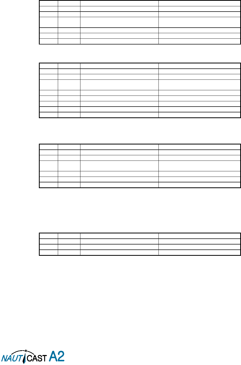
Page 58 of 80 1001001-2EN A2 Product Manual 2_0
8.4 Long Range Input Sentences
8.4.1 On Long Range Port
The LR sentences can only be used with the Long Range interface port.
8.4.1.1 LRF – AIS long-range function
$--LRF,x,xxxxxxxxx,c—c,c—c,c—c
Field
Format
Name
Comment
1
--LRF
Sentence Id
Used
2
x
Sequence number
Used
3
xxxxxxxx
x
MMSI of requestor
Used
4
c--c
Name of requestor
Used
5
c--c
Function request
Used
6
c--c
Function reply status
Used
8.4.1.2 LRI – AIS long-range interrogation
$--LRI,x,a,xxxxxxxxx,xxxxxxxxx,llll.ll,a,yyyyy.yy,a,llll.ll,a,yyyyy.yy,a
Field
Format
Name
Comment
1
--LRI
Sentence Id
Used
2
x
Sequence number
Used
3
xxxxxxxx
x
MMSI of requestor
Used
4
xxxxxxxx
MMSI of destination
Used
5
llll.ll
Latitude
Used
6
a
N / S
Used
7
yyyyy.yy
Longitude
Used
8
a
E / W
Used
8.4.2 On Other Input Ports
LRF – AIS long-range function
$--LRF,x,xxxxxxxxx,c—c,c—c,c—c
Field
Format
Name
Comment
1
--LRF
Sentence Id
Used
2
x
Sequence number
Used
3
xxxxxxxx
x
MMSI of requestor
Used
4
c--c
Name of requestor
Used
5
c--c
Function request
Used
6
c--c
Function reply status
Used
8.5 Proprietary Input Sentences
All Nauticast Proprietary Sentences will have talker ID PSTT.
8.5.1 Proprietary Query message PSTT,101
$PSTT,101,c--c,
Field
Format
Name
Comment
1
PSTT
Proprietary Nauticast Sentence
Used
2
101
Sentence Query
Used
3
c--c
Proprietary sentence to query
Used
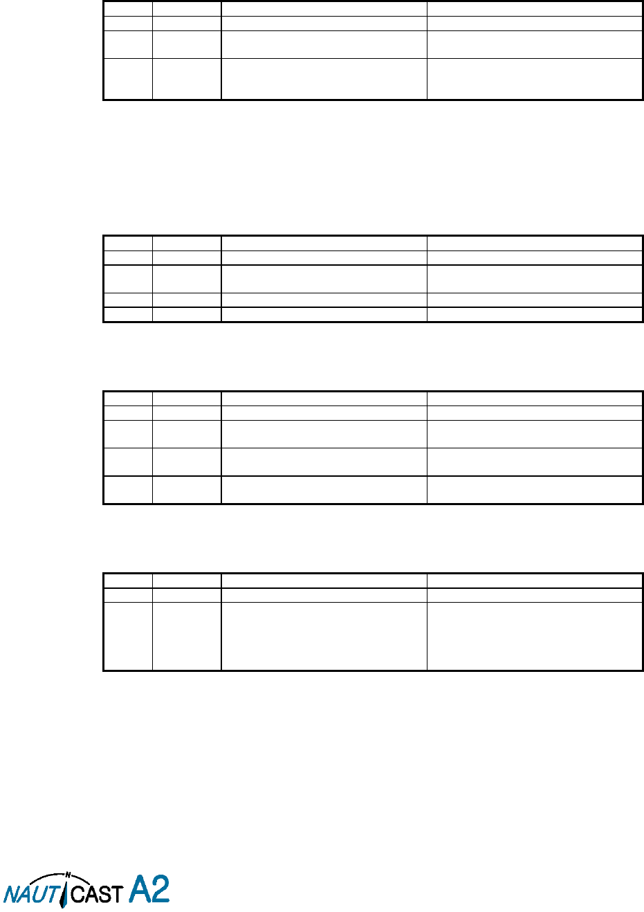
Page 59 of 80 1001001-2EN A2 Product Manual 2_0
9 Interpretation of Output Sentences
9.1 Proprietary Output Sentences (PSTT)
In addition to the standardized IEC sentences, the NAUTICAST A2 is able to output the proprietary sentences
listed below. All Nauticast Proprietary Sentences have talker ID “PSTT”.
9.1.1 $PSTT,10A – UTC Date and Time
This sentence provides UTC Date and Time, i.e. NAUTICAST A2 system time (based on internal GNSS time).
It is output approximately once every 10 seconds (± 1 s).
$PSTT,10A,YYYYMMDD,HHMMSS
Field
Format
Name
Comment
1
10A
Sentence Id
10A always
2
YYYYMMDD
Date
Year, month and day in decimal notation.
(00000000 = Not available)
3
HHMMSS
Time
Hour, minute and second in decimal
notation.
(999999 = Not available)
Example: $PSTT,10A,20121028,135230*<FCS><CR><LF>
= Date October 28, 2012
= Time 13:52:30 UTC
9.1.2 $PSTT,10C – Data Link Status
This sentence provides information about the traffic on the VHF data link. It is output approximately once
every 60 seconds. Traffic load is calculated over the last frame (i.e. 60 seconds). Number of units is derived
from the internal user list and is generally the number of received units within the last few minutes.
$PSTT,10C,C,LLL,NNNN
Field
Format
Name
Comment
1
10C
Sentence Id
10C always
2
C
Channel
A = VDL Channel A
B = VDL Channel B
3
LLL
Traffic Load
Data link traffic load in precent, 0-100.
4
NNNN
Number of Units
Number of units occupying the data link
9.1.3 $PSTT,146 – System Operational Mode Status
This sentence reports the system operational mode. This sentence is output on change, periodically every
minute and on request using PSTT,101.
$PSTT,146,x,x,x*hh<CR><LF>
Field
Format
Name
Comment
1
146
Sentence Id
146 always
2
X
1 W Mode
0 = Default
1 = 1 Watt
3
X
System Mode
0 = Class A
1 = Inland
4
X
Transmit mode
0 = Normal
1 = Silent
9.1.4 $PSTT,1F3 – Transponder Restart
This sentence will be output when the transponder has restarted.
$PSTT,1F3,R
Field
Format
Name
Comment
1
1F3
Sentence Id
1F3 always
2
R
Restart Reason
0 = Unknown
1 = Cold Start
2 = General Protection Fault
3 = Power Fail
4 = Warm Start

Page 60 of 80 1001001-2EN A2 Product Manual 2_0
9.2 Long Range Output Sentences
9.2.1 On Long Range Port
9.2.1.1 LR1 – AIS long-range reply sentence 1
$--LR1,x,xxxxxxxxx,xxxxxxxxx,c—c,c—c,xxxxxxxxx
Field
Format
Name
Comment
1
--LR1
Sentence Id
Used
2
x
Sequence number
Used
3
xxxxxxxx
x
MMSI of responder
Used
4
xxxxxxxx
x
MMSI of requestor (reply destination
Used
5
c--c
Ship’s name
Used
6
c--c
Call sign
Used
7
xxxxxxxx
x
IMO Number
Used
9.2.1.2 LR2 – AIS long-range reply sentence 2
$--LR2,x,xxxxxxxxx,xxxxxxxx,hhmmss.ss,llll.ll,a,yyyyy.yy,a,x.x,T,x.x,N
Field
Format
Name
Comment
1
--LR2
Sentence Id
Used
2
x
Sequence number
Used
3
xxxxxxxx
x
MMSI of responder
Used
4
xxxxxxxx
Date
Used
5
hhmmss.s
s
UTC time of position
Used
6
llll.ll
Latitude
Used
7
a
N / S
Used
8
yyyyy.yy
Longitude
Used
9
a
E / W
Used
10
x.x
Course over ground
Used
11
T
Validity of COG
Used
12
x.x
Speed over ground
Used
13
N
Validity of SOG
Used
9.2.1.3 LR3 – AIS long-range reply sentence 3
$--LR3,x,xxxxxxxxx,c—c,xxxxxx,hhmmss.ss,x.x,x.x,x.x,x.x,x.x,x.x
Output rate: On event
Field
Format
Name
Comment
1
--LR3
Sentence Id
Used
2
x
Sequence number
Used
3
xxxxxxxx
x
MMSI of responder
Used
4
c--c
Voyage destination
Used
5
xxxxxxxx
ETA Date
Used
6
hhmmss.s
s
ETA time
Used
7
x.x
Draught
Used
8
x.x
Ship / Cargo
Used
9
x.x
Ship length
Used
10
x.x
Ship width
Used
11
x.x
Ship type
Used
12
x.x
Persons
Used

Page 61 of 80 1001001-2EN A2 Product Manual 2_0
9.2.1.4 LRF – AIS long-range function
$--LRF,x,xxxxxxxxx,c—c,c—c,c—c
Output rate: On event
Field
Format
Name
Comment
1
--LRF
Sentence Id
Used
2
x
Sequence number
Used
3
xxxxxxxx
x
MMSI of requestor
Used
4
c--c
Name of requestor
Used
5
c--c
Function request
Used
6
c--c
Function reply status
Used
9.2.2 On All Other Output Ports
9.2.2.1 LRF – AIS long-range function
$--LRF,x,xxxxxxxxx,c—c,c—c,c—c
Output rate: On event
Field
Format
Name
Comment
1
--LRF
Sentence Id
Used
2
x
Sequence number
Used
3
xxxxxxxx
x
MMSI of requestor
Used
4
c--c
Name of requestor
Used
5
c--c
Function request
Used
6
c--c
Function reply status
Used
9.2.2.2 LRI – AIS long-range interrogation
$--LRI,x,a,xxxxxxxxx,xxxxxxxxx,llll.ll,a,yyyyy.yy,a,llll.ll,a,yyyyy.yy,a
Output rate: On event
Field
Format
Name
Comment
1
--LRI
Sentence Id
Used
2
x
Sequence number
Used
3
xxxxxxxx
x
MMSI of requestor
Used
4
xxxxxxxx
MMSI of destination
Used
5
llll.ll
Latitude
Used
6
a
N / S
Used
7
yyyyy.yy
Longitude
Used
8
a
E / W
Used
9.3 AIS Output Sentences
9.3.1 ABK – AIS Addressed and binary broadcast acknowledgement
$ -- ABK,xxxxxxxxx,x,x.x,x,x
Output rate: On event.
Field
Format
Name
Comment
1
--ABK
Sentence Id
Used
2
xxxxxxxxx
MMSI of the addressed AIS unit
Used
3
x
AIS channel of reception
Used
4
x.x
ITU - R M.1371 Message ID
Used
5
x
Message sequence number
Used
6
x
Type of acknowledgement
Used

Page 62 of 80 1001001-2EN A2 Product Manual 2_0
9.3.2 ACA – AIS Regional Channel Assignment Message
$--ACA,x,llll.ll,a,yyyy.yy,a,llll.ll,a,yyyy.yy,a,x,xxxx,x,xxxx,x,x,x,a,x,
hhmmss.ss
Output rate: On event. On request.
Field
Format
Name
Comment
1
--ACA
Sentence Id
Used
2
x
Sequence number
Ignored
3
llll.ll
NE latitude (2 fields)
Used
4
a
5
yyyy.yy
NE longitude (2 fields)
Used
6
a
7
llll.ll
SW latitude (2 fields)
Used
8
a
9
yyyy.yy
SW longitude (2 fields)
Used
10
a
11
x
Transitional zone size
Used
12
xxxx
Channel A
Used
13
x
Channel A bandwidth
Used
14
xxxx
Channel B
Used
15
x
Channel B bandwidth
Used
16
x
Tx/Rx mode
Used
17
x
Power level
Used
18
a
Information source
Ignored
19
x
In use flag
Ignored
20
hhmmss.s
s
Time of In use change
Ignored
9.3.3 ALR – Set alarm state
$--ALR,hhmmss.ss,xxx,A, A,c--c
Output rate: On event, on request, and automatically. Output every 30s for active alarms and every 60s when
no active alarms.
Field
Format
Name
Comment
1
--ALR
Sentence Id
Used
2
hhmmss.ss
Time of alarm condition change,
UTC
Used
3
Xxx
Unique alarm number (identifier) at
alarm source
Used
4
A
Alarm condition
A = threshold exceeded
V = not exceeded
Used
5
A
Alarm’s acknowledge state A =
acknowledged
V = unacknowledged
Used
6
c--c
Alarm’s description text
Used
9.3.4 EPV – Command or report equipment property value
$--EPV,a,c--c,c--c,x.x,c—c
Output rate: On request.
Field
Format
Name
Comment
1
--EPV
Sentence Id
Used
2
a
Sentence status flag
Used
3
c--c
Destination equipment type
Used
4
c--c
Unique Identifier
Used
5
x.x
Property identifier
Used
6
c--c
Value of property
Used
9.3.5 NAK – Negative acknowledgement
$--NAK,cc,ccc,c--c,x.x,c—c
Output rate: On event
Field
Format
Name
Comment
1
--NAK
Sentence Id
Used
2
cc
Talker identifier
Used
3
ccc
Affected sentence formatter
Used
4
c--c
Unique Identifier
Used
5
x.x
Reason code for negative
acknowledgement
Used
6
c--c
Negative acknowledgement’s descriptive
text
Used
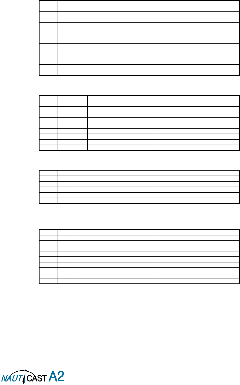
Page 63 of 80 1001001-2EN A2 Product Manual 2_0
9.3.6 SSD – Ship Static Data
$--SSD,c--c,c--c,xxx,xxx,xx,xx,c,aa
Output rate: On request.
Field
Format
Name
Comment
1
--SSD
Sentence Id
Used
2
c--c
Call sign
Used, may be NULL
3
c--c
Name
Used, may be NULL
4
xxx
Pos ref A
Used to change position reference for the
position source in use. May be NULL.
5
xxx
Pos ref B
Used to change position reference for the
position source in use. May be NULL.
6
xx
Pos ref C
Used to change position reference for the
position source in use. May be NULL.
7
xx
Pos ref D
Used to change position reference for the
position source in use. May be NULL.
8
c
DTE
Ignored
9
aa
Source identifier
Ignored
9.3.7 TRL – AIS transmitter non functioning log
$--TRL,x.x,x.x,x,xxxxxxxx,hhmmss.ss,xxxxxxxx,hhmmss.ss,x
Output rate: On request. Up to 10 sentences in a burst.
Field
Format
Name
Comment
1
--TRL
Sentence Id
Used
2
x.x
Total number of log entries
Used
3
x.x
Log entry number
Used
4
x
Sequential message identifier
Used
5
xxxxxxxx
Switch off date
Used
6
hhmmss.ss
Switch off UTC time
Used
7
xxxxxxxx
Switch on date
Used
8
hhmmss.ss
Switch on UTC time
Used
9
X
Reason code1
Used
9.3.8 TXT – Text transmission
$--TXT,xx,xx,xx,c--c
Output rate: On request, on event.
Field
Format
Name
Comment
1
--TXT
Sentence Id
Used
2
xx
Total number of sentences
Used
3
xx
Sentence number
Used
4
xx
Text identifier
Used
5
c--c
Text message
Used
9.3.9 VDM – AIS VHF data-link message
!--VDM,x,x,x,a,s—s,x
Only output on serial port when baudrate is 38400 bps or higher.
Output rate: On VHF message receive event.
Field
Format
Name
Comment
1
--VDM
Sentence Id
Used
2
X
Total number of sentences needed to
transfer the message
Used
3
X
Sentence number
Used
4
X
Sequential message identifier
Used
5
A
AIS channel
Used
6
s—s
Encapsulated ITU-R M.1371 radio
message
Used
7
X
Number of fill bits
Used

Page 64 of 80 1001001-2EN A2 Product Manual 2_0
9.3.10 VDO – AIS VHF data-link own-vessel report
!--VDO,x,x,x,a,s—s,x
Only output on serial port when baudrate is 38400 bps or higher.
Output rate: On VHF transmission event. “Dummy” messages once per second.
Field
Format
Name
Comment
1
--VDO
Sentence Id
Used
2
X
Total number of sentences needed to
transfer the message
Used
3
X
Sentence number
Used
4
X
Sequential message identifier
Used
5
A
AIS channel
Used for transmission event. Not used for
“dummy” position messages.
6
s—s
Encapsulated ITU-R M.1371 radio
message
Used
7
X
Number of fill bits
Used
9.3.11 VER – Version
$--VER,x,x,aa,c--c,c--c,c--c,c--c,c--c,c--c,x
Output rate: On request.
Field
Format
Name
Comment
1
--VER
Sentence Id
Used
2
x
Total number of sentences
Always 1
3
x
Sentence number
Always 1
4
aa
Device Type
Used
5
c--c
Vendor ID
Used
6
c--c
Unique Identifier
Used
7
c--c
Manufacturer serial number
Used
8
c--c
Model code
Used
9
c--c
Software revision
Used
10
c--c
Hardware revision
Used
11
x
Sequential message identifier
Always NULL
9.3.12 VSD – Voyage Static Data
$--VSD,x.x,x.x,x.x,c--c,hhmmss.ss,xx,xx,x.x,x.x
Output rate: On request.
Field
Format
Name
Comment
1
--VSD
Sentence Id
Used
2
x.x
Type of ship and cargo
Used
3
x.x
Maximum present draught
Used
4
x.x
Persons on-board
Used
5
c--c
Destination
Used
6
hhmmss.s
s
Est. UTC of arrival
Used
7
Xx
Est. day of arrival
Used
8
Xx
Est. month of arrival
Used
9
x.x
Navigational status
Used
10
x.x
Regional application flags
Used

Page 65 of 80 1001001-2EN A2 Product Manual 2_0
10 Glossary
ACK
Acknowledgement
AFSK
Audio Frequency Shift Keying
AIS
Automatic Identification System
Ant
Antenna
App
Application
ARPA
Automatic Radar Plotting Aid
BRG
Bearing
BS
Base Station
Ch
Channel
COG
Course Over Ground
Comm
Communication
DGNSS
Differential Global Navigational Satellite System
Disp
Display
DTE
Data Terminal Equipment
DSC
Digital Selective Calling
ECDIS
Electronic Chart Display and Information System
EGNOS
European Geostationary Navigation Overlay Service
EPFS
Electronic Position Fixing System
ETA
Estimated Time of Arrival
Ext
External
GALILEO
European GNSS
GLONASS
Russian GNSS
GMSK
Gaussian Minimum Shift Keying
GNSS
Global Navigational Satellite System
GPS
Global Positioning System
HDG
Heading
HDOP
Horizontal Dilution Of Precision
Hecto
Hectometre
H/W
Hardware
IALA
International Association of Lighthouse Authorities
ID
Identifier
IEC
International Electrotechnical Commission
IMO
International Maritime Organization
Int
Internal
ITU
International Telecommunications Union
LAT
Latitude
LED
Light Emitting Diode
LOC
Local
LON
Longitude
LR
Long Range
Msg
Message
MKD
Minimum Keyboard and Display
MSAS
MTSAT Satellite Augmentation System (Japan)
NMEA
National Marine Electronics Association
MMSI
Maritime Mobile Service Identity
N/A
Not available
NE
North East

Page 66 of 80 1001001-2EN A2 Product Manual 2_0
No
Number
NVM
Non-Volatile Memory
PoB
Persons on board
Pos
Position
RAIM
Receiver Autonomous Integrity Monitoring
RNG
Range
RATDMA
Random Access Time Division Multiple Access
ROT
Rate Of Turn
RTA
Recommended Time of Arrival
Rx
Receive
SAR
Search And Rescue
SART
Search And Rescue Transmitter
SBAS
Satellite Based Augmentation System
SNR
Signal to Noise Ratio
SOG
Speed Over Ground
SRM
Safety Related Message
Sync
Synchronization
SW
South West
S/W
Software
TDMA
Time Division Multiple Access
Transp
Transponder
Tx
Transmit
UN
United Nations
UTC
Universal Time Coordinated
VHF
Very High Frequency
VSWR
Voltage Standing Wave Ratio. (A low value indicates a problem with the antenna or connections/cables to
the antenna.)
WAAS
Wide Area Augmentation System (United States)

Page 67 of 80 1001001-2EN A2 Product Manual 2_0
10.1 Inland ERI Ship Types
ERI Ship Type
Description
IMO Ship Type
8000
Vessel Type Unknown
99
8010
Motor Freighter
79
8020
Motor Tanker
89
8021
Motor Tanker Liquid (N)
80
8022
Motor Tanker Liquid (C)
80
8023
Motor Tanker Dry Cargo
89
8030
Container Vessel
79
8040
Gas Tanker
80
8050
Motor Freighter Tug
79
8060
Motor Tanker Tug
89
8070
Motor Freighter (Ships Alongs.)
79
8080
Motor Freighter With Tanker
89
8090
Motor Freighter Push Freighter(s)
79
8100
Motor Freighter Push Tank-Ship(s)
89
8110
Tug Freighter
79
8120
Tug Tanker
89
8130
Tug Freighter Coupled
31
8140
Tug Freighter/Tanker Coupled
31
8150
Freightbarge
99
8160
Tankbarge
99
8161
Tankbarge Liquid cargo (N)
90
8162
Tankbarge Liquid cargo (C)
90
8163
Tankbarge Dry Cargo
99
8170
Freightbarge Containers
89
8180
Tankbarge Gas
90
8210
Pushtow One Cargo Barge
79
8220
Pushtow 2 Cargo Barges
79
8230
Pushtow 3 Cargo Barges
79
8240
Pushtow 4 Cargo Barges
79
8250
Pushtow 5 Cargo Barges
79
8260
Pushtow 6 Cargo Barges
79
8270
Pushtow 7 Cargo Barges
79
8280
Pushtow 8 Cargo Barges
79
8290
Pushtow >=9 Cargo Barges
79
8310
Pushtow one Tank/Gas barge
80
8320
Pushtow 2 Barges (>= 1 T/G)
80
8330
Pushtow 3 Barges (>= 1 T/G)
80
8340
Pushtow 4 Barges (>= 1 T/G)
80
8350
Pushtow 5 Barges (>= 1 T/G)
80
8360
Pushtow 6 Barges (>= 1 T/G)
80
8370
Pushtow 7 Barges (>= 1 T/G)
80
8380
Pushtow 8 Barges (>= 1 T/G)
80
8390
Pushtow >=9 Barges (>= 1 T/G)
80
8400
Tug Single
52
8410
Tug One or More Tows
31
8420
Tug Assisting a Vessel or Linked.
31
8430
Pushboat Single
99
8440
Passenger Ship Ferry Cruise
69
8441
Ferry
69
8442
Red Cross Ship
58
8443
Cruise Ship
69
8444
Passenger Ship No Accomodation
69
8450
Service Vessel Police etc.
99
8460
Vessel Maint. Derric etc.
33
8470
Object Towed
99
8480
Fishing Boat
30
8490
Bunkership
99
8500
Barge Tanker Chemical
80
8510
Object Not Specified
99
1500
General Cargo Vessel
79
1510
Unit Carrier Maritime
79
1520
Bulk Carrier Maritime
79
1530
Tanker
80
1540
Liquified Gas Tanker
80
1850
Pleasure Craft >= 20m
37
1900
Fast Ship
49
1910
Hydrofoil
49

Page 68 of 80 1001001-2EN A2 Product Manual 2_0
10.2 Units
bps
Bits per second
W
Watt
m
Meter
kHz
Kilo Hertz
dB-Hz
Decibel-Hertz
NM
Nautical Mile
km
Kilometer
Sm
Statute Mile
kn
Knots
km/h
Kilometer per Hour
mph
Miles per Hour
mm-dd hh:mm
month-day hour:minute
h:m:s
hours:minutes:seconds
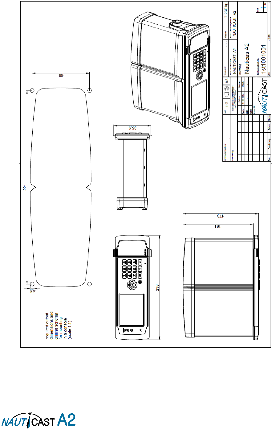
Page 69 of 80 1001001-2EN A2 Product Manual 2_0
11 Appendix
11.1 Appendix A – Drawings
11.1.1 Panel Mounting:
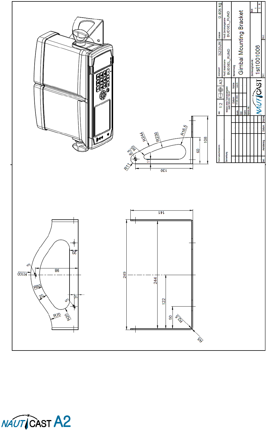
Page 70 of 80 1001001-2EN A2 Product Manual 2_0
11.1.2 Gimbal Mount:
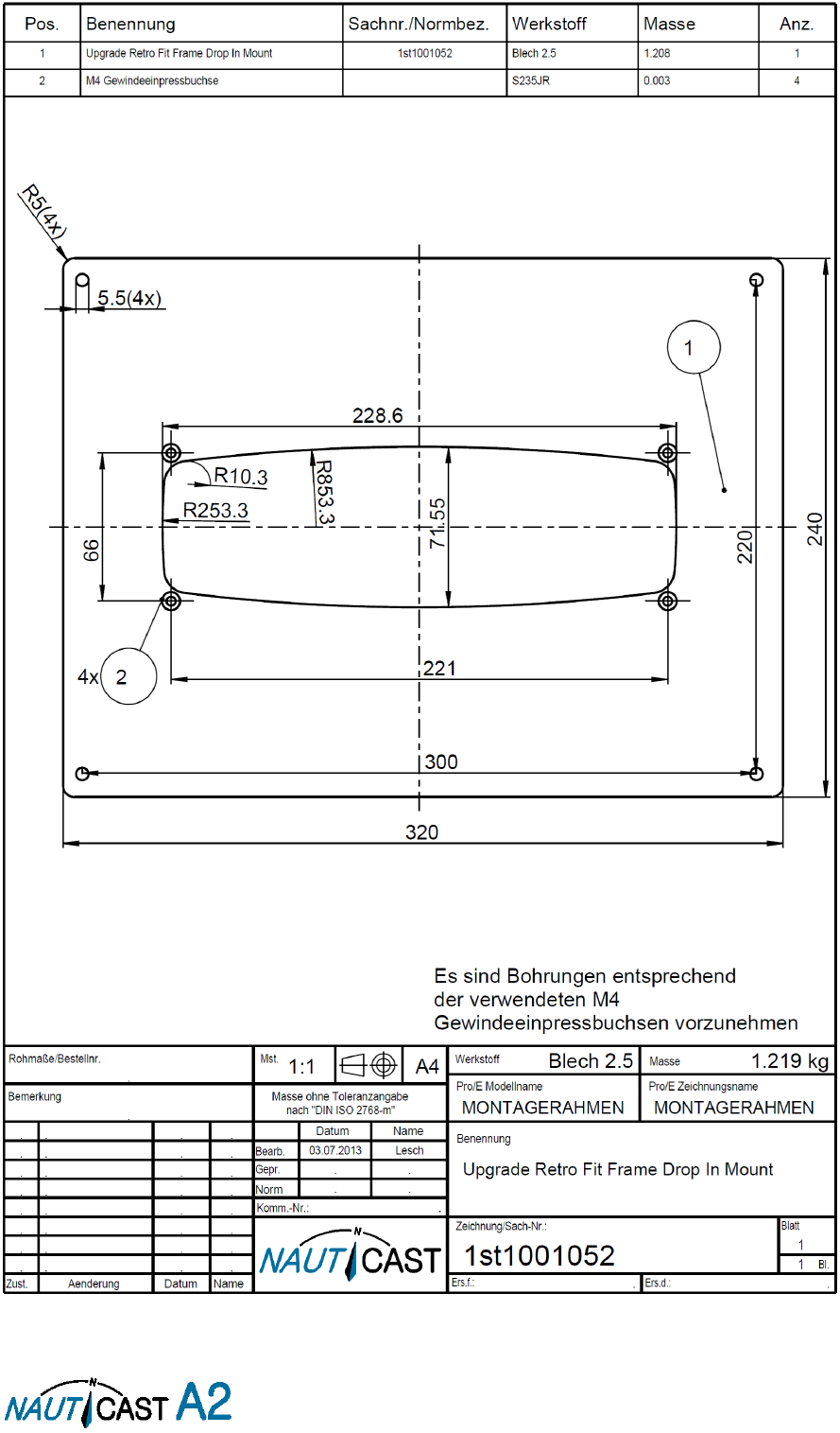
Page 71 of 80 1001001-2EN A2 Product Manual 2_0
11.1.3 Upgrade Retrofit Frame

Page 72 of 80 1001001-2EN A2 Product Manual 2_0
11.2 Appendix B – License
The NAUTICAST A2 Transponder System runs on a Linux operating system which is licensed with GNU General
Public License. The source code of the Linux kernel can be obtained by contacting Nauticast GmbH:
Email: support@nauticast.com
Copy of the GNU General Public License:
GNU GENERAL PUBLIC LICENSE
Version 2, June 1991
Copyright (C) 1989, 1991 Free Software Foundation, Inc. 51 Franklin St, Fifth Floor, Boston, MA 02110-1301 USA; Everyone is permitted
to copy and distribute verbatim copies of this license document, but changing it is not allowed.
Preamble
The licenses for most software are designed to take away your freedom to share and change it. By contrast, the GNU General Public
License is intended to guarantee your freedom to share and change free software--to make sure the software is free for all its users. This
General Public License applies to most of the Free Software Foundation's software and to any other program whose authors commit to
using it. (Some other Free Software Foundation software is covered by the GNU Library General Public License instead.) You can apply it
to your programs, too.
When we speak of free software, we are referring to freedom, not price. Our General Public Licenses are designed to make sure that you
have the freedom to distribute copies of free software (and charge for this service if you wish), that you receive source code or can get
it if you want it, that you can change the software or use pieces of it in new free programs; and that you know you can do these things.
To protect your rights, we need to make restrictions that forbid anyone to deny you these rights or to ask you to surrender the rights.
These restrictions translate to certain responsibilities for you if you distribute copies of the software, or if you modify it.
For example, if you distribute copies of such a program, whether gratis or for a fee, you must give the recipients all the rights that you
have. You must make sure that they, too, receive or can get the source code. And you must show them these terms so they know their
rights.
We protect your rights with two steps: (1) copyright the software, and (2) offer you this license which gives you legal permission to copy,
distribute and/or modify the software.
Also, for each author's protection and ours, we want to make certain that everyone understands that there is no warranty for this free
software. If the software is modified by someone else and passed on, we want its recipients to know that what they have is not the
original, so that any problems introduced by others will not reflect on the original authors' reputations.
Finally, any free program is threatened constantly by software patents. We wish to avoid the danger that redistributors of a free program
will individually obtain patent licenses, in effect making the program proprietary. To prevent this, we have made it clear that any patent
must be licensed for everyone's free use or not licensed at all.
The precise terms and conditions for copying, distribution and modification follow.
GNU GENERAL PUBLIC LICENSE
TERMS AND CONDITIONS FOR COPYING, DISTRIBUTION AND MODIFICATION
0. This License applies to any program or other work which contains a notice placed by the copyright holder saying it may be distributed
under the terms of this General Public License. The "Program", below, refers to any such program or work, and a "work based on the
Program" means either the Program or any derivative work under copyright law: that is to say, a work containing the Program or a portion
of it, either verbatim or with modifications and/or translated into another language. (Hereinafter, translation is included without limitation
in the term "modification".) Each licensee is addressed as "you".
Activities other than copying, distribution and modification are not covered by this License; they are outside its scope. The act of running
the Program is not restricted, and the output from the Program is covered only if its contents constitute a work based on the Program
(independent of having been made by running the Program). Whether that is true depends on what the Program does.
1. You may copy and distribute verbatim copies of the Program's source code as you receive it, in any medium, provided that you
conspicuously and appropriately publish on each copy an appropriate copyright notice and disclaimer of warranty; keep intact all the
notices that refer to this License and to the absence of any warranty; and give any other recipients of the Program a copy of this License
along with the Program.
You may charge a fee for the physical act of transferring a copy, and you may at your option offer warranty protection in exchange for a
fee.
2. You may modify your copy or copies of the Program or any portion of it, thus forming a work based on the Program, and copy and
distribute such modifications or work under the terms of Section 1 above, provided that you also meet all of these conditions:
a) You must cause the modified files to carry prominent notices stating that you changed the files and the date of any change.
b) You must cause any work that you distribute or publish, that in whole or in part contains or is derived from the Program or any part
thereof, to be licensed as a whole at no charge to all third parties under the terms of this License.
c) If the modified program normally reads commands interactively when run, you must cause it, when started running for such
interactive use in the most ordinary way, to print or display an announcement including an appropriate copyright notice and a notice
that there is no warranty (or else, saying that you provide a warranty) and that users may redistribute the program under these
conditions, and telling the user how to view a copy of this License. (Exception: if the Program itself is interactive but does not
normally print such an announcement, your work based on the Program is not required to print an announcement.)
These requirements apply to the modified work as a whole. If identifiable sections of that work are not derived from the Program, and
can be reasonably considered independent and separate works in themselves, then this License, and its terms, do not apply to those
sections when you distribute them as separate works. But when you distribute the same sections as part of a whole which is a work based
on the Program, the distribution of the whole must be on the terms of this License, whose permissions for other licensees extend to the
entire whole, and thus to each and every part regardless of who wrote it.
Thus, it is not the intent of this section to claim rights or contest your rights to work written entirely by you; rather, the intent is to
exercise the right to control the distribution of derivative or collective works based on the Program.
In addition, mere aggregation of another work not based on the Program with the Program (or with a work based on the Program) on a
volume of a storage or distribution medium does not bring the other work under the scope of this License.
3. You may copy and distribute the Program (or a work based on it, under Section 2) in object code or executable form under the terms
of Sections 1 and 2 above provided that you also do one of the following:
a) Accompany it with the complete corresponding machine-readable source code, which must be distributed under the terms of Sections
1 and 2 above on a medium customarily used for software interchange; or,

Page 73 of 80 1001001-2EN A2 Product Manual 2_0
b) Accompany it with a written offer, valid for at least three years, to give any third party, for a charge no more than your cost of
physically performing source distribution, a complete machine-readable copy of the corresponding source code, to be distributed
under the terms of Sections 1 and 2 above on a medium customarily used for software interchange; or,
c) Accompany it with the information you received as to the offer to distribute corresponding source code. (This alternative is allowed
only for noncommercial distribution and only if you received the program in object code or executable form with such an offer, in
accord with Subsection b above.)
The source code for a work means the preferred form of the work for making modifications to it. For an executable work, complete source
code means all the source code for all modules it contains, plus any associated interface definition files, plus the scripts used to control
compilation and installation of the executable. However, as a special exception, the source code distributed need not include anything
that is normally distributed (in either source or binary form) with the major components (compiler, kernel, and so on) of the operating
system on which the executable runs, unless that component itself accompanies the executable.
If distribution of executable or object code is made by offering access to copy from a designated place, then offering equivalent access
to copy the source code from the same place counts as distribution of the source code, even though third parties are not compelled to
copy the source along with the object code.
4. You may not copy, modify, sublicense, or distribute the Program except as expressly provided under this License. Any attempt otherwise
to copy, modify, sublicense or distribute the Program is void, and will automatically terminate your rights under this License. However,
parties who have received copies, or rights, from you under this License will not have their licenses terminated so long as such parties
remain in full compliance.
5. You are not required to accept this License, since you have not signed it. However, nothing else grants you permission to modify or
distribute the Program or its derivative works. These actions are prohibited by law if you do not accept this License. Therefore, by
modifying or distributing the Program (or any work based on the Program), you indicate your acceptance of this License to do so, and all
its terms and conditions for copying, distributing or modifying the Program or works based on it.
6. Each time you redistribute the Program (or any work based on the Program), the recipient automatically receives a license from the
original licensor to copy, distribute or modify the Program subject to these terms and conditions. You may not impose any further
restrictions on the recipients' exercise of the rights granted herein. You are not responsible for enforcing compliance by third parties to
this License.
7. If, as a consequence of a court judgment or allegation of patent infringement or for any other reason (not limited to patent issues),
conditions are imposed on you (whether by court order, agreement or otherwise) that contradict the conditions of this License, they do
not excuse you from the conditions of this License. If you cannot distribute so as to satisfy simultaneously your obligations under this
License and any other pertinent obligations, then as a consequence you may not distribute the Program at all. For example, if a patent
license would not permit royalty-free redistribution of the Program by all those who receive copies directly or indirectly through you, then
the only way you could satisfy both it and this License would be to refrain entirely from distribution of the Program.
If any portion of this section is held invalid or unenforceable under any particular circumstance, the balance of the section is intended to
apply and the section as a whole is intended to apply in other circumstances.
It is not the purpose of this section to induce you to infringe any patents or other property right claims or to contest validity of any such
claims; this section has the sole purpose of protecting the integrity of the free software distribution system, which is implemented by
public license practices. Many people have made generous contributions to the wide range of software distributed through that system in
reliance on consistent application of that system; it is up to the author/donor to decide if he or she is willing to distribute software through
any other system and a licensee cannot impose that choice.
This section is intended to make thoroughly clear what is believed to be a consequence of the rest of this License.
8. If the distribution and/or use of the Program is restricted in certain countries either by patents or by copyrighted interfaces, the original
copyright holder who places the Program under this License may add an explicit geographical distribution limitation excluding those
countries, so that distribution is permitted only in or among countries not thus excluded. In such case, this License incorporates the
limitation as if written in the body of this License.
9. The Free Software Foundation may publish revised and/or new versions of the General Public License from time to time. Such new
versions will be similar in spirit to the present version, but may differ in detail to address new problems or concerns.
Each version is given a distinguishing version number. If the Program specifies a version number of this License which applies to it and
"any later version", you have the option of following the terms and conditions either of that version or of any later version published by
the Free Software Foundation. If the Program does not specify a version number of this License, you may choose any version ever
published by the Free Software Foundation.
10. If you wish to incorporate parts of the Program into other free programs whose distribution conditions are different, write to the
author to ask for permission. For software which is copyrighted by the Free Software Foundation, write to the Free Software Foundation;
we sometimes make exceptions for this. Our decision will be guided by the two goals of preserving the free status of all derivatives of our
free software and of promoting the sharing and reuse of software generally.
NO WARRANTY
11. BECAUSE THE PROGRAM IS LICENSED FREE OF CHARGE, THERE IS NO WARRANTY FOR THE PROGRAM, TO THE EXTENT PERMITTED
BY APPLICABLE LAW. EXCEPT WHEN OTHERWISE STATED IN WRITING THE COPYRIGHT HOLDERS AND/OR OTHER PARTIES PROVIDE
THE PROGRAM "AS IS" WITHOUT WARRANTY OF ANY KIND, EITHER EXPRESSED OR IMPLIED, INCLUDING, BUT NOT LIMITED TO, THE
IMPLIED WARRANTIES OF MERCHANTABILITY AND FITNESS FOR A PARTICULAR PURPOSE. THE ENTIRE RISK AS TO THE QUALITY
AND PERFORMANCE OF THE PROGRAM IS WITH YOU. SHOULD THE PROGRAM PROVE DEFECTIVE, YOU ASSUME THE COST OF ALL
NECESSARY SERVICING, REPAIR OR CORRECTION.
12. IN NO EVENT UNLESS REQUIRED BY APPLICABLE LAW OR AGREED TO IN WRITING WILL ANY COPYRIGHT HOLDER, OR ANY OTHER
PARTY WHO MAY MODIFY AND/OR REDISTRIBUTE THE PROGRAM AS PERMITTED ABOVE, BE LIABLE TO YOU FOR DAMAGES,
INCLUDING ANY GENERAL, SPECIAL, INCIDENTAL OR CONSEQUENTIAL DAMAGES ARISING OUT OF THE USE OR INABILITY TO USE
THE PROGRAM (INCLUDING BUT NOT LIMITED TO LOSS OF DATA OR DATA BEING RENDERED INACCURATE OR LOSSES SUSTAINED
BY YOU OR THIRD PARTIES OR A FAILURE OF THE PROGRAM TO OPERATE WITH ANY OTHER PROGRAMS), EVEN IF SUCH HOLDER OR
OTHER PARTY HAS BEEN ADVISED OF THE POSSIBILITY OF SUCH DAMAGES.
END OF TERMS AND CONDITIONS
How to Apply These Terms to Your New Programs
If you develop a new program, and you want it to be of the greatest possible use to the public, the best way to achieve
this is to make it free software which everyone can redistribute and change under these terms.
To do so, attach the following notices to the program. It is safest to attach them to the start of each source file to most
effectively convey the exclusion of warranty; and each file should have at least the "copyright" line and a pointer to
where the full notice is found.
<one line to give the program's name and a brief idea of what it does.>

Page 74 of 80 1001001-2EN A2 Product Manual 2_0
Copyright (C) <year> <name of author>
This program is free software; you can redistribute it and/or modify
it under the terms of the GNU General Public License as published by
the Free Software Foundation; either version 2 of the License, or
(at your option) any later version.
This program is distributed in the hope that it will be useful,
but WITHOUT ANY WARRANTY; without even the implied warranty of
MERCHANTABILITY or FITNESS FOR A PARTICULAR PURPOSE. See the
GNU General Public License for more details.
You should have received a copy of the GNU General Public License
along with this program; if not, write to the Free Software
Foundation, Inc., 51 Franklin St, Fifth Floor, Boston, MA 02110-1301 USA
Also add information on how to contact you by electronic and paper mail.
If the program is interactive, make it output a short notice like this when it starts in an interactive mode:
Gnomovision version 69, Copyright (C) year name of author
Gnomovision comes with ABSOLUTELY NO WARRANTY; for details type `show w'.
This is free software, and you are welcome to redistribute it
under certain conditions; type `show c' for details.
The hypothetical commands `show w' and `show c' should show the appropriate parts of the General Public License.
Of course, the commands you use may be called something other than `show w' and `show c'; they could even be
mouse-clicks or menu items--whatever suits your program.
You should also get your employer (if you work as a programmer) or your school, if any, to sign a "copyright
disclaimer" for the program, if necessary. Here is a sample; alter the names:
Yoyodyne, Inc., hereby disclaims all copyright interest in the program
`Gnomovision' (which makes passes at compilers) written by James Hacker.
<signature of Ty Coon>, 1 April 1989
Ty Coon, President of Vice
This General Public License does not permit incorporating your program into proprietary programs. If your program is a
subroutine library, you may consider it more useful to permit linking proprietary applications with the library. If this is
what you want to do, use the GNU Library General Public License instead of this License.
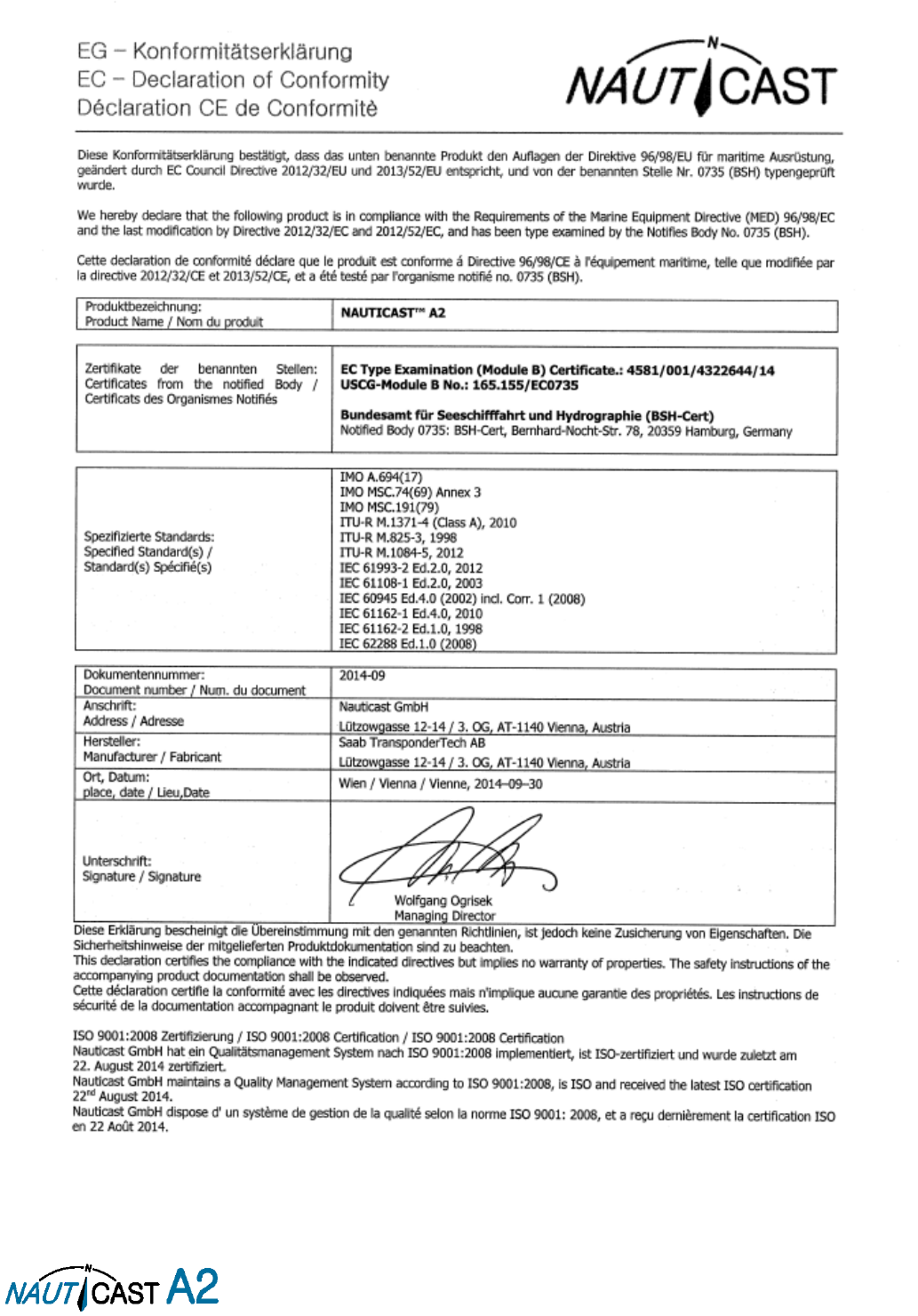
Page 75 of 80 1001001-2EN A2 Product Manual 2_0
11.3 Appendix C – Declaration of Conformity
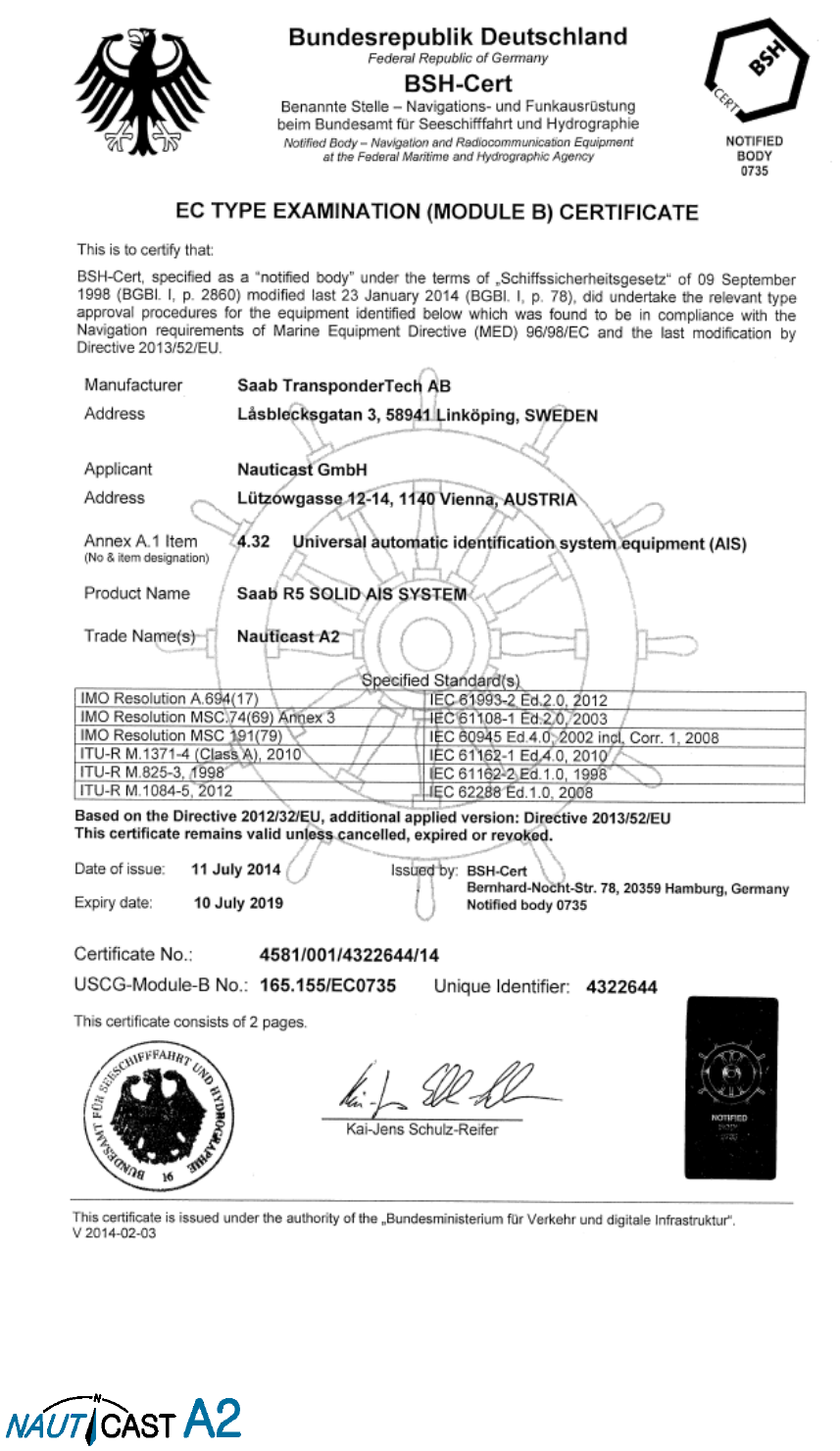
Page 76 of 80 1001001-2EN A2 Product Manual 2_0
11.4 Appendix D – Certification
Page 77 of 80 1001001-2EN A2 Product Manual 2_0

Page 78 of 80 1001001-2EN A2 Product Manual 2_0

Nauticast GmbH
Lützowgasse 12-14 / 3.OG
1140 Vienna, Austria
T: +43 (1) 5 237 237-0
F: +43 (1) 5 237 237-150
office@nauticast.com
For more information
and the latest updates visit us at
www.nauticast.com