Navico Auckland HS35 2.4 GHz TRANSCEIVER User Manual Operation Manual
Navico Auckland Limited 2.4 GHz TRANSCEIVER Operation Manual
Contents
- 1. Installation Manual
- 2. Operation Manual
Operation Manual
simrad-yachting.com
ENGLISH
RS35 VHF
User Guide

Copyright © 2013 Navico
All rights reserved.
Simrad® is a registered trademark of Navico
No part of this manual may be copied, reproduced, republished, transmitted or
distributed for any purpose, without prior written consent of Simrad Electronics.
Any unauthorized commercial distribution of this manual is
strictly prohibited.
Simrad Electronics may find it necessary to change or end our policies, regulations,
and special offers at any time. We reserve the right to do so without notice. All
features and specifications subject to change without notice.
All screens in this manual are simulated.
For free owner’s manuals and the most current information on this product, its
operation and accessories, visit our website: www.simrad-yachting.com
Important safety information
Please read carefully before installation and use.
DANGER
This is the safety alert symbol. It is used to alert you to potential
personal injury hazards, Obey all safety messages that follow this
symbol to avoid possible injury or death.
WARNING WARNING indicates a potentially hazardous situation which, if not
avoided, could result in death or serious injury
CAUTION CAUTION indicates a potentially hazardous situation which, if not
avoided, could result in minor or moderate injury.
CAUTION
CAUTION used without the safety alert symbol indicates a
potentially hazardous situation which, if not avoided, may result in
property damage.
Simrad - RS35 Operation Instructions 3
Section 1 - General information .......................................................................7
1-1 Features ................................................................................................................................................7
1-2 Customizing your Simrad VHF radio ...........................................................................................8
1-3 How to display and navigate menus .........................................................................................8
1-4 How to enter alphanumeric data .................................................................................................8
1-5 LCD symbols and meanings .......................................................................................................... 8
1-3 Beep tones & call alerts ................................................................................................................. 10
Section 2 - Basic operation and key functions ...............................................11
Section 3 - Radio MENU SELECT options .........................................................17
3-1 Manage your waypoints list (WAYPOINT) .............................................................................. 18
3-1-1 Add a new waypoint ...................................................................................................................................18
3-1-2 Edit or delete a waypoint .........................................................................................................................18
3-1-3 Go to a new waypoint ...............................................................................................................................19
3-1-4 Go to nearest waypoint (NEAREST WP) ...........................................................................................19
3-1-5 Go to temporary waypoint .....................................................................................................................20
3-1-6 Edit or delete a temporary waypoint ................................................................................................20
3-1-7 Send waypoint data to a chartplotter .............................................................................................. 21
3-2 Set the backlighting level (BACKLIGHT) ............................................................................... 21
3-3 Maintain your buddy list (BUDDY LIST) .................................................................................. 22
3-3-1 Add an entry ...................................................................................................................................................22
3-3-2 Edit or delete an entry ..............................................................................................................................23
3-4 Local or distance sensitivity (LOCAL/DIST) ........................................................................... 23
3-4-1 Set distance sensitivity ...............................................................................................................................23
3-4-2 Set local sensitivity .......................................................................................................................................24
3-5 Set the contrast level (CONTRAST) .......................................................................................... 24
3-6 GPS data and time (GPS/DATA) ................................................................................................. 24
3-6-1 Manually enter position and UTC time (MANUAL) ................................................................25
3-6-2 Local time (TIME OFFSET) ........................................................................................................................25
3-6-3 Time format options (TIME FORMAT) .............................................................................................. 26
3-6-4 Time display options (TIME DISPLY) .................................................................................................26
3-6-5 Position display options (LL DISPLY) ................................................................................................27
3-6-6 Course & speed display options (COG/SOG) ..............................................................................27
3-6-7 GPS alert (GPS ALERT) ...............................................................................................................................28
3-7 GPS simulator (GPS SIM) .............................................................................................................. 28
3-8 Reset to factory defaults (RESET) ............................................................................................. 28
Section 4 - Radio setup menu (RADIO SETUP) ................................................29
4-1 Channel (UIC) ................................................................................................................................... 29
4-2 Channel names (CH NAME) ........................................................................................................ 29
Simrad - RS35 Operation InstructionsSimrad - RS35 Operation Instructions 54
4-3 Ring volume (RING VOLUME) ..................................................................................................... 30
4-4 Key beep volume (KEY BEEP) ..................................................................................................... 30
4-5 Select units (UNITS) ........................................................................................................................ 31
4-6 Internal speaker connections (INT SPEAKER) ........................................................................ 31
4-7 Set the priority channel (WATCH MODE) ................................................................................ 31
4-8 Weather alerts (WX ALERT).......................................................................................................... 32
4-8-1 TONE ALERT ......................................................................................................................................................32
4-8-2 SAME ALERT......................................................................................................................................................32
4-8-3 Receiving a SAME ALERT ..........................................................................................................................33
4-8-4 Receiving SAME TEST messages ..........................................................................................................33
4-8-5 Enter a SAME CODE (County ID) ..........................................................................................................33
4-8-6 Select a working SAME code .................................................................................................................34
4-9 NMEA protocol (COM PORT) ..................................................................................................... 35
4-10 Select the GPS source (GPS SOURCE) .................................................................................... 35
4-11 Favourite channel setup - Wx key (FAV CH SETU) ............................................................. 35
Section 5 - DSC setup menu (DSC SETUP) ........................................................36
5-1 Enter or view your USER MMSI (USER MMSI) ........................................................................ 36
5-2 Maintain your groups ................................................................................................................... 37
5-2-1 Create a group (GROUP SETUP) ...........................................................................................................37
5-2-2 Edit or delete a group name or group MMSI (GROUP SETUP) .......................................... 38
5-3 Enter or check your ATIS MMSI (ATIS MMSI) .......................................................................... 38
5-4 Enable ATIS functionality (ATIS SELECT) ................................................................................. 39
5-5 Response to individual calls (INDIV REPLY) ........................................................................... 40
5-6 Enable DSC functionality (DSC FUNC) ..................................................................................... 40
5-7 Response type to LL polling calls (LL REPLY) ........................................................................ 41
5-8 Automatic channel switching (AUTO SWITCH) .................................................................... 41
5-9 DSC Test Reply (TEST REPLY) ....................................................................................................... 42
5-10 Set the inactivity timer (TIMEOUT) ........................................................................................ 42
Section 6 - AIS setup menu (AIS SETUP) ...........................................................43
6-1 Enable AIS functionality (AIS FUNC) ......................................................................................... 43
6-2 AIS data display format (AIS DISPLAY) ..................................................................................... 43
6-3 AIS baud rate (BAUD RATE) .......................................................................................................... 43
6-4 GPS redirection (GPS REDIR) ....................................................................................................... 44
6-5 Closest point of approach alarm (CPA ALARM) .................................................................... 44
6-6 Closest point of approach settings (CPA) ............................................................................... 44
6-7 Time to closest point of approach (TCPA) .............................................................................. 44
Section 7 - Wireless handset setup menu (HS SETTING) .................................45
7-1 Register a wireless handset (SUBSCRIBE) ............................................................................... 45
7-2 Delete a registered wireless handset (REGISTERED HS) .................................................... 45
Section 8 - Sending and receiving DSC Calls ..................................................46
8-1 What is DSC? .................................................................................................................................... 46
8-2 Sending DSC Calls ........................................................................................................................... 46
8-3 Send an individual call (INDIVIDUAL) ...................................................................................... 47
Call to a Buddy .............................................................................................................................................................47
Call to others .................................................................................................................................................................47
8-4 Acknowledgement of an individual incoming call (INDIV) ............................................. 48
8-5 Reply to the Last Call (LAST CALL) ............................................................................................ 48
8-6 Send a group call (GROUP) ......................................................................................................... 49
8-7 Send an all ships call (ALL SHIPS) .............................................................................................. 49
8-8 Send using the call log (CALL LOG) .......................................................................................... 50
8-9 Send using the distress log (DIST LOG) ................................................................................... 51
8-10 View sent call log (SENT CALL) ................................................................................................. 52
8-11 Request the LL position of a Buddy (LL REQUEST) ........................................................... 52
8-12 Track your Buddy (TRACK BUDDY) ......................................................................................... 53
8-12-1 Start or stop tracking a Buddy (START TRACK) .........................................................................53
8-12-2 Select a Buddy to Track (SET BUDDY) ............................................................................................ 53
8-12-3 Add or delete a Buddy on your track list (TRACKLIST) ........................................................54
8-12-4 Set the track your Buddy update interval (INTERVAL) ........................................................54
8-13 Make a DSC test call (DSC TEST) .............................................................................................. 54
8-13-1 Send a DSC TEST call ................................................................................................................................54
8-13-2 Receiving an incoming DSC TEST call reply (DSC TEST ACK) ..........................................55
8-13-3 Acknowledging an incoming DSC TEST call .............................................................................55
8-14 View user MMSI and GPS information ................................................................................... 56
8-15 Receiving DSC calls ...................................................................................................................... 56
8-16 Receiving an all ships call (ALL SHIPS) .................................................................................. 56
8-17 Receiving an individual call (INDIV) ....................................................................................... 57
8-18 Receiving a group call (GROUP) .............................................................................................. 57
8-19 Receiving a geographic area call (GEOGRAPH) ................................................................. 58
8-20 Receiving a polled position call (POSITION) ....................................................................... 58
Section 9 - DISTRESS calls ................................................................................59
9-1 Sending a Distress Call ................................................................................................................. 59
9-2 Receiving a distress call (DISTRESS!) ......................................................................................... 60
9-3 Distress acknowledgement (DISTRESS ACK) or distress relay all ships (DISTRESS

Section 1 - General information
1-1 Features
Congratulations on your purchase of this Simrad RS35 marine band VHF radio. Your RS35
provides you with the following useful features:
• Access to all currently available Marine VHF Channel Banks (USA, Canada, International)
including weather channels where available (model dependant)
• DSC (Digital Select Calling) capability that meets Class D standards
• Separate CH70 DSC receiver built in
• ATIS facility for inland waterways (EU models)
• 10 weather channels (where available)
• NOAA and SAME weather alert capability (US models)
• Dual channel AIS receiver built in - receive AIS transmissions (receive only)
• Choice of High or Low (25 W or 1 W) transmission power
• Special CH16 or CH16/9 key for quick access to the priority (International Distress)
channel
• DISTRESS call button to automatically transmit the MMSI and position until an
acknowledgement is received
• Special 3CH key for quick selection of your three favorite channels
• Memory channel scan and All channel priority scan
• Dual/Tri Watch capability
• Call log for the 20 most recent incoming DSC calls
• Distress call log for the 20 most recent distress calls
• Easy access to a buddy list of up to 20 favorite people
• MMSI storage for 20 favorite groups
• GROUP CALL and ALL SHIPS CALL facility
• LL position polling and Track Your Buddy feature
• Automatic position and time update when connected to a GPS receiver
• Adjustable keypad backlighting for easy night-time use
• Adjustable contrast settings for the LCD
• Waterproof and submersible to comply with JIS-7
• Rotary channel selector knob with Push To Select function
• Speaker microphone with large PTT key and 6 keys for easy channel and mode selection
• 30 W Hailer with listen back capability
• Foghorn (manual and automatic)
• Great Circle GPS navigation calculations to a waypoint (stores up to 200 waypoints)
• NMEA 2000 & NMEA 0183 connectivity
• Local/Distance sensitivity to eliminate noise in high traffic urban areas.
• Ability to communicate with up to two optional wireless handsets (HS35)
Simrad - RS35 Operation InstructionsSimrad - RS35 Operation Instructions 76
REL) .............................................................................................................................................................. 61
9-4 Distress relay individual (INDIV DISTR RELAY) ...................................................................... 61
Section 10 - AIS functionality...........................................................................62
10-1 About AIS ......................................................................................................................................... 62
10-2 AIS - Static and dynamic information .................................................................................... 62
10-3 Using the AIS receiver ................................................................................................................. 63
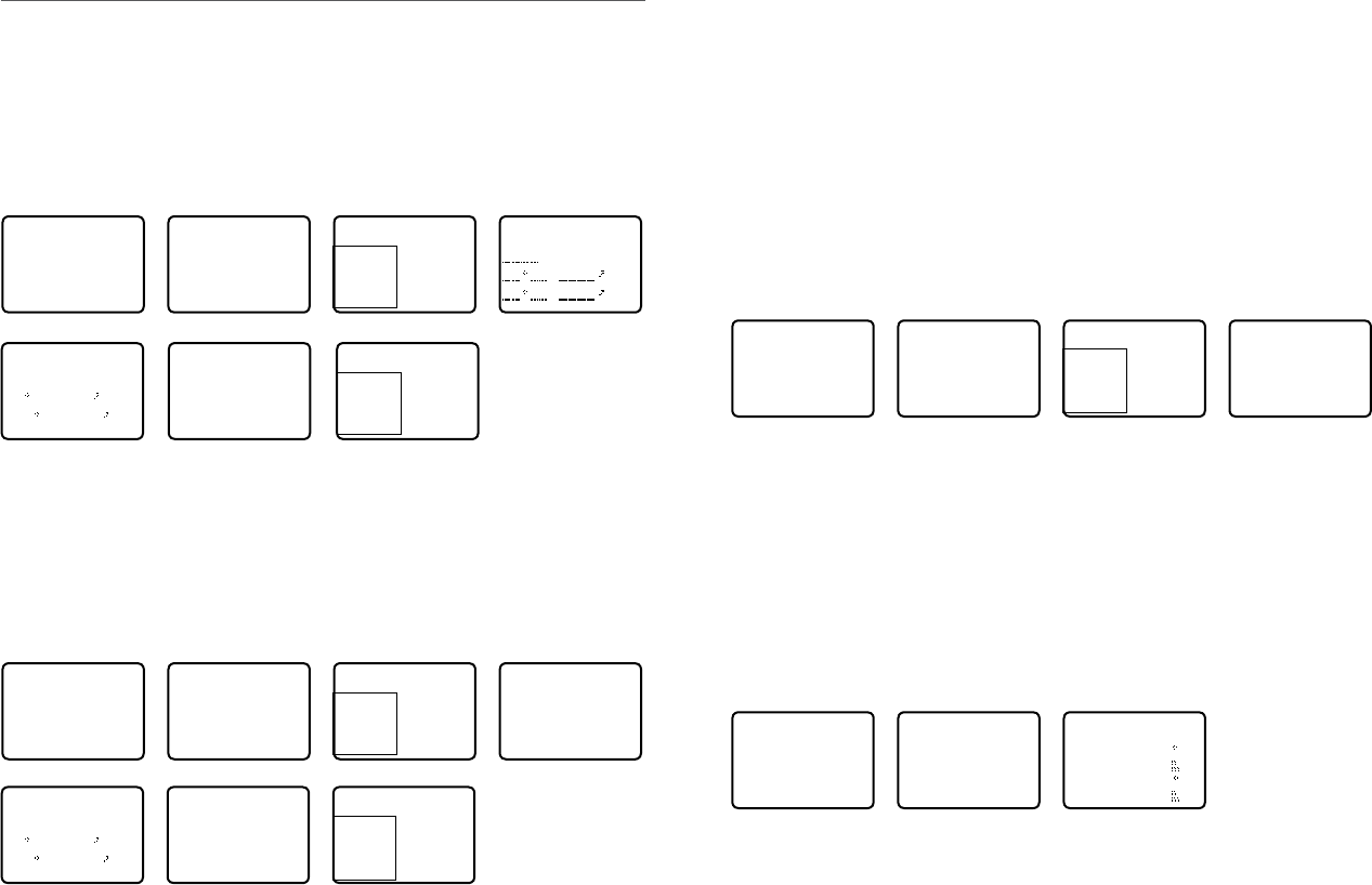
10-4 AIS Information and display ..................................................................................................... 64
10-4-1 T/CPA approach screen...........................................................................................................................65
10-4-2 Plotter symbols and meanings ..........................................................................................................65
Section 11 - General functionality ...................................................................66
11-1 Using the Fog Horn ...................................................................................................................... 66
11-2 Using the PA (Public Address) Hailer ..................................................................................... 67
Section 12 - Wireless Handset functionality ...................................................68
12-1 Using the Wireless Handset ...................................................................................................... 68
12-2 Using the Intercom / Conference facility ............................................................................. 68
Appendix A - Technical specifications ............................................................70
Simrad RS35 ................................................................................................................................................................... 70
RS35 NMEA 2000 PGNS ......................................................................................................................................... 73
Appendix B - Troubleshooting ........................................................................74
Appendix C - US & ROW VHF marine channel charts ......................................75
C-1 International channel chart ........................................................................................................ 75
Special notes on international channel usage.........................................................................................76
C-2 USA channel chart .......................................................................................................................... 77
Special notes on USA channel usage ............................................................................................................78
C-3 CANADA channel chart ................................................................................................................ 79
Special notes on Canada channel usage ....................................................................................................80
C-4 US & Canada WEATHER channels .............................................................................................. 81
C-5 EAS (Emergency Alert Systems) alerts .................................................................................... 82
Appendix D - EU VHF marine channel charts .................................................84
D-1 EU international channel chart ................................................................................................. 84
Special notes on EU international channel usage .................................................................................85
D-2 Inland waterways country specic table - ATIS ON ........................................................... 86
D-3 Special channels ............................................................................................................................. 89
Appendix E - MMSI and license information ...................................................90
Countries of intended use in the EU: .................................................................. 90
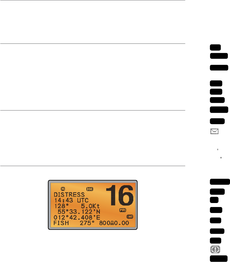
• your current course (128°) and speed (5.0Kt)
• your latitude (55°33.122N) and longitude (012°42.408E) and UTC time displayed in 24
hour format (14:43 - 2:43pm)
• the name of the destination waypoint (FISH), its bearing (275°), your distance in nautical
miles, mile, or kilometres (depending on your choice of units) - in this case, 800nm, and
the cross track error (XTE - 0.00) are shown.
All the symbols that may appear on the LCD are explained here:
Symbol Meaning
TX
Transmitting.
Receiver busy with an incoming signal.
SCAN
Scanning for the broadcasting channel. Press PTT to stop scanning.
When the broadcasting channel is found, scanning stops at that
channel.
DW
Dual watch mode.
TRI
Tri watch mode.
DSC
DSC function is enabled.
ATIS
ATIS is enabled for use in European inland waterways. Otherwise,
blank.
AIS
AIS function is enabled.
Incoming DSC call, or blinks to notify you of any unread call log
messages.
DISTRESS Channel name tag.
55 33.122N Your latitude.
012 42.408E Your longitude.
14:43 UTC Time (UTC). Local time has suffix LOC (for example; 12:30pm LOC).
16 Channel selected.
LOCAL
Local calling is selected. Otherwise, blank for distance calling.
SKIP
Channel is temporarily deleted ‘skipped’ from the SCAN operation.
A
Channel suffix, if applicable - A or B - otherwise blank.
CH1
Shows which of the 3 favorite channels, if any, are selected.
CH1, CH2, CH3 - otherwise blank.
Hi
Transmission power. High (Hi) 25 W or Low (Lo) 1 W.
INT
Selected channel bank for VHF radio operations and regulations.
INT=International; USA=USA; CAN=CANADA.
Wx
Weather channel.
Weather alert. US only.
SAME
Specific Area Message Encoding. US only.
BUSY
1-2 Customizing your Simrad VHF radio
You can customize the radio to suit your individual preferences. Some preferences can be set
directly through the keys as explained in this section.
Other preferences are set up through the built-in menus and these are explained in the other
sections.
1-3 How to display and navigate menus
1. Press MENU (or CALL) key.
2. Some line items may show an ▲ or ▼ indicator. This means there is more information
available to show. Scroll (rotate the Rotary knob, or use + / - keys on the handset mic) to
scroll up and down the menu until the cursor is positioned at the desired option. Press
ENT (press the Push To Select) to display that option.
3. Make any entries or changes as explained in the following section.
4. Press ENT to confirm changes. Otherwise, press EXIT to keep the original entry.
5. Press EXIT to backup one screen (this key is equivalent to an ESC function on a PC).
1-4 How to enter alphanumeric data
If your radio does not have the optional alphanumeric microphone, you can rotate the rotary
knob, or use +/- keys on the handset mic to enter alphanumeric data.
• Press - to count through numbers, or hold down to scroll rapidly to the desired number
• Press + to step through the alphabet, or hold down to scroll rapidly to the desired character
• If you make an error, press - until < is displayed, then press ENT to backup and correct
the entry.
1-5 LCD symbols and meanings
A typical operational display is shown here:
The bottom line is blank when a waypoint is not selected. This operational display shows:
• the channel that you are receiving (16) and Tx power is set to high (Hi)
• the International channel bank selected (INT) and DSC is enabled (DSC)
• the channel name tag (DISTRESS)
Simrad - RS35 Operation InstructionsSimrad - RS35 Operation Instructions 98
D
Duplex operation. Otherwise, blank for Simplex operation.
PRI
Priority channel is selected.
ACK Your DSC call has been received.
Low Battery warning (activates at 10.5 V).
FISH 275 Waypoint name and bearing.
800nm Distance to waypoint.
0.00 XTE (Cross track error).
NO GPS GPS data is not available.
X
AUTO SWITCH is disabled.
1-3 Beep tones & call alerts
• Error 2 short beeps
• Acknowledge 1 long beep
• Alarm Two-tone ring
(repeated for 2 minutes or until any key is pressed)
• LL position call alert Friendly 5-tone ring sequence
(press any key to cancel)
• WX alert/SAME alert Ear-catching multi-tone sequence
• ROUTINE call alert Friendly 5-tone ring sequence
(press any key to cancel)
• URGENCY call alert Two-tone ring
(repeated for 2 minutes or until any key is pressed)
• SAFETY call alert Two-tone ring
(repeated for 2 minutes or until any key is pressed)
• DISTRESS call alert Two-tone ring
(repeated for 2 minutes or until any key is pressed)
Section 2 - Basic operation and key functions
All possible keys and their functions are listed here. Note that some of the keys may
not be available, depending on your Simrad VHF radio model.
Key: Function:
VOL / Volume and Power
Turn clockwise to power on. Continue to turn until a comfortable volume is reached.
VOL / will also adjust the settings of an external speaker, if connected.
SQL Squelch or Threshold Level
Sets the threshold level for the minimum receiver signal. Turn fully counterclockwise
until random noise is heard, then turn slowly clockwise until the random noise
disappears. Make another 1/4 turn clockwise for best reception in open sea conditions.
In areas of high noise (eg. close to large cities) reception may improve if sensitivity is
reduced. Either turn SQL slowly clockwise or use the LOCAL setting. See section 3-4.
16 / 9 Priority channel
Also on the handset mic. Press to cancel all other modes and to tune into the priority
channel. Press again to return to your original channel. The default Priority Channel is
CH16.
For US models: To make Channel 09 the priority channel, hold down 16/9 until a
beep sounds and 09 is displayed.
DISTRESS Send a DSC Distress Call
DSC must be active and an MMSI must be programmed. See Section 7.
Lift the red cover door then press and release DISTRESS to show the DISTRESS menu.
Select the category you want to transmit. Hold down DISTRESS for about 3 seconds
to transmit.
The DISTRESS key can also be held down continuously to transmit an “undefined”
category Distress call.
See Section 8 for more information about distress calls.
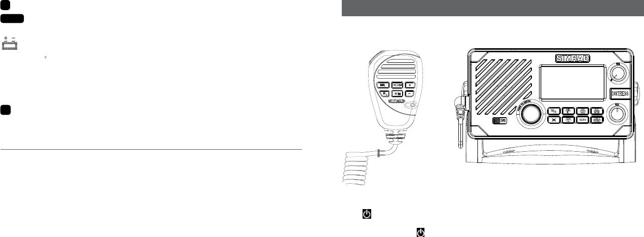
6 Key handset mic RS35 base station radio
Simrad - RS35 Operation InstructionsSimrad - RS35 Operation Instructions 1110
PTT Press To Talk
(Located on the handset mic). Press PTT to transmit at any time on an allowable
channel. This automatically exits you from menu mode and stops scanning. You must
release PTT to receive a signal.
If PTT sticks, a built-in timer will automatically shut down a transmission after five
minutes and sound a short error beep.
PUSH TO SELECT
Enter (ENT)
When you are in MENU mode, push the center of the Channel Select knob to enter
your choice or setting. This is referred to throughout the manual as “press ENT”.
Rotary knob Channel select
Turn to select a channel. The current channel is shown on the LCD in BIG digits and an
A or B designator suffix (if applicable) in small letters below the channel number.
See Appendix C for a complete listing of channel charts.
Push to activate the ENT function.
Alphanumeric entry
You can also use the rotary knob for alphanumeric entry. Turn to step through
alphanumeric characters one at a time, then push to confirm each selection. If you
make an error, select the < character then push to backup.
+ / - Channel select
(Located on the handset mic). The current channel is shown on the screen in BIG digits
with an appropriate designator suffix A or B in small letters below the channel number.
Press + or - to step through the available channels one at a time, or hold down to
scroll rapidly through all the available channels.
See Appendix C for a complete listing of channel charts.
Alphanumeric entry
This key can be used for both menu selection and for alphanumeric entry. Press + or -
to scroll the cursor up or down to menu options when navigating menus.
When editing an item containing only numbers, press - to count through the numbers
or hold down to scroll rapidly.
To enter a character, press + to step through the alphabet or hold down to scroll
rapidly.
X Escape (ESC)
Use EXIT when navigating menus, to clear incorrect entries, to exit from a menu
without saving changes, and to back up to the previous screen.
CALL/MENU DSC CALL menu
Quick press to enter the DSC CALL menu and make DSC calls. See Section 5.
Radio and DSC setup MENU mode
Hold down for about 1 second to show the radio MENU so that you can customize
your radio. See section 4.
WX/NAV Weather channel
For US models: In USA and Canadian waters, press to hear the most recently selected
weather station. The WX symbol
Wx
is displayed on the LCD. Rotate the dial or + / -
on the handset mic to change to a different weather channel. Press WX again to return
to the most recent channel. If the weather alert mode (ALT) is ON and an alert tone of
1050 Hz is broadcast from the weather station, it is picked up automatically and the
alarm sounds. Press any key to hear the weather alert voice message.
Note: If SAME is activated and the 6 digit County IDs you want to monitor are entered,
the radio will sound the weather alarm when it detects a weather alert or weather
hazard alert on the selected weather channel.
For all other models: The Wx key can be programmed to a weather channel of your
choice. See section 4-11 to program your favourite channel.
NAV (Show waypoint)
Hold down for about 1 second to enter the Navigation mode.
If a waypoint is already selected, the bearing and distance to the waypoint and the
cross track error are shown on the bottom line of the LCD.
If you are in Navigation mode and want to scan all the VHF channels while staying in
Navigation mode, just hold down SCAN.
Press SCAN to quit scanning.
3CH Three favourite channels
Also on the handset mic. Press to toggle between your favourite channels. The CH1,
CH2, or CH3 symbol appears on the LCD to show which favourite channel is selected.
To scan only one of your favourite channels, press 3CH then immediately press
and release SCAN. If you want to scan all three favourite channels, press 3CH then
immediately press and hold SCAN.
To add a favourite channel for the first time, select that channel then hold 3CH to store
it in the CH1 location. Repeat the procedure to store two more favourite channels in
the CH2 and CH3 locations respectively.
If you try and add another favourite channel it will overwrite the existing CH3. CH1
and CH2 remain unless you delete them.
To delete a favourite channel, select that channel then hold down 3CH until the CH1,
CH2 or CH3 symbol disappears off the LCD.
Simrad - RS35 Operation InstructionsSimrad - RS35 Operation Instructions 1312
SCAN Scan (ALL SCAN & 3CH SCAN)
There are two SCAN modes you can use to find the broadcast channel:
• ALLSCANmodescansALLchannelsinsequence,andchecksthepriority
channel every 2 seconds.
• 3CHSCANmodescansthefavoritechannelsandCH16.
When a signal is received, scanning stops at that channel and
BUSY
appears on the
LCD. If the signal ceases for more than 5 seconds, the scan restarts.
Press SCAN or PTT to stop at the current channel.
If you are in NAVIGATION mode and want to scan the DSC channels while staying in
that mode, just hold down SCAN.
Note: SCAN functionality is limited in some European countries and, if ATIS mode is
enabled, the 3CH SCAN mode will be disabled and an error beep will sound.
Note: The weather channel is also scanned if TONE ALERT or SAME is ON (US only).
ALL SCAN mode:
Hold down SCAN for about 3 seconds to start an ALL SCAN. ALL SCAN appears on the
LCD.
Press ENT to temporarily skip over (lock out) an “always busy” channel when in ALL
SCAN mode.
SKIP
is shown on the top line of the LCD to designate a skipped
channel. SKIP will disappear when the radio is powered OFF/ON. With scanning OFF
and the SKIP channel selected, press ENT to cancel the skipped channel.
Note: It is not possible to skip over the priority channel.
Press SCAN to stop at the current channel.
Press EXIT to cancel scan mode and return to normal operation.
3CH SCAN mode
With any of your three favorite channels selected (by pressing the 3CH key) hold down
SCAN to start all 3CH scanning. Press SCAN again to stop at the broadcast channel,
or press EXIT to quit 3CH SCAN and return automatically to the previous broadcast
channel.
AIS / IC AIS (Automatic Identication System)
Quick press to enter the AIS menu.
See section 6 for AIS setup or Section 9 for AIS functionality.
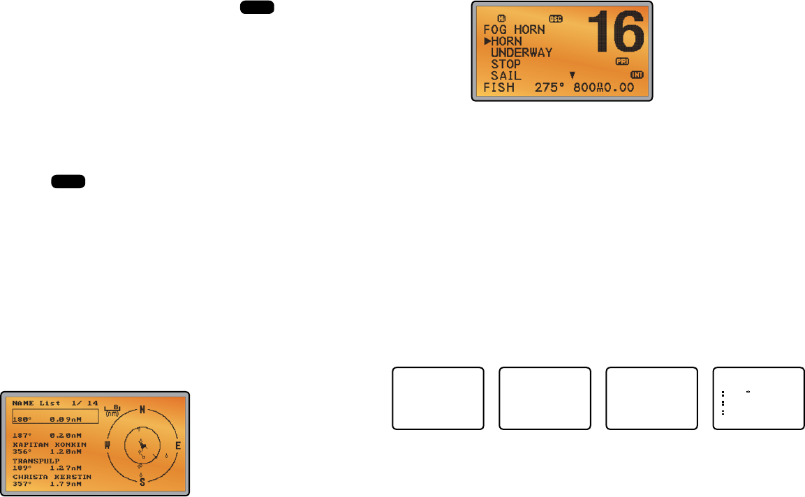
IC (FOG HORN mode)
Hold down for about 1 second to enter HAILER mode. Select FOG HORN. The FOG
HORN will sound certain international standard fog horn tones through the hailer
speaker depending on the mode selected.
See section 10 for HAILER functionality.
IC (PA HAILER mode)
Hold down for about 1 second to enter HAILER mode. Select PA (Public Address). The
PA allows you to make an announcement at high volume to people or vessels using
the RS35 hand mic.
See section 10 for HAILER functionality.
GO / MOB GO (Reset the Cross Track Error)
Note: A valid GPS signal must be received to see this selection.
Press GO if you are navigating to a waypoint and want to reset the cross track error.
This is a very useful single keystroke feature to use if you wander a little off-course but
want to continue to your active waypoint.
The bearing and distance to the waypoint and any cross track error are shown on the
bottom line of the LCD.
MOB (Man Over Board)
Hold down MOB until the radio automatically enters Navigation mode, saves your cur-
rent latitude and longitude as the MOB waypoint and immediately sets this position
as the destination waypoint.
You will see the following sequence of LCDs:
HOLD 3 SEC
FOR MOB
RELEASE TO
SAVE
HOLD 2 SEC
FOR MOB
RELEASE TO
SAVE
HOLD 1 SEC
FOR MOB
RELEASE TO
SAVE
MOB
B010
D0.01
X0.00
The bearing and distance to the Man Overboard position, and any cross track error
(XTE), are shown on the bottom line of the LCD.
To cancel MOB, select another waypoint.
Simrad - RS35 Operation InstructionsSimrad - RS35 Operation Instructions 1514

MOB (Temporary waypoint)
To mark your current position as a temporary waypoint, hold down MOB and release
the key before the 3 second countdown ends.
You will see the following sequence of LCDs:
HOLD 3 SEC
FOR MOB
RELEASE TO
SAVE
HOLD 2 SEC
FOR MOB
RELEASE TO
SAVE
HOLD 1 SEC
FOR MOB
RELEASE TO
SAVE
The new temporary waypoint is shown in your waypoints list. Hold down MENU, press
ENT, then press ENT again to display the waypoints list (TEMP1, WP001, WP002).
You cannot store more than three temporary waypoints. If you store another tempo-
rary waypoint, TEMP1 is overwritten with the new information.
H/L Transmission power
(Located on the handset mic). High (HI) 25 W or Low (LO) 1 W. Press to toggle between
high or low transmission power for the entire channel bank. The HI or LO selection is
shown on the LCD.
Some channels allow only low power transmissions. Error beeps will sound if the
power transmission setting is incorrect.
Some channels allow only low power transmissions initially, but can be changed to
high power by holding down H/L and PTT at the same time.
See Appendix C for a complete listing of channel charts.
Softkeys: This radio uses virtual softkeys during certain functions. A softkey is defined by a name
that appears at the bottom of the LCD that positioned immediately above an actual
key on the radio. A softkey provides you with the additional function or choice when
the softkey appears during certain functions:
ACK Able key (WX/NAV key)
Press to ACK (acknowledge) a DSC call.
ACCEPT Accept key (AIS/IC key)
Press to ACCEPT a channel request. The radio will immediately change to the
requested channel.
NEW-CH New channel request key (AIS/IC key)
Press to request a new channel.
PAUSE PAUSE key (WX/NAV key)
Press to pause a call when in repeat mode.
RESEND Resend key (AIS/IC key)
Press to resend the DSC call.
SILENC Silence key (AIS/IC key)
Provided as an option to silence an audible alarm.
Simrad - RS35 Operation Instructions16

Section 3 - Radio MENU SELECT options
Hold down CALL MENU for about 1 second to access any of the following radio MENU SELECT options.
Menu options shown inside the gray boxes are explained in this section.
Simrad - RS35 Operation Instructions 17
WAYPOINT Section 3-1
BACKLIGHT Section 3-2
BUDDY LIST Section 3-3
LOCAL/DIST Section 3-4
CONTRAST Section 3-5
GPS/DATA MANUAL Section 3-6-1
SETTING TIME OFFSET Section 3-6-2
TIME FORMAT Section 3-6-3
TIME DISPLY Section 3-6-4
LL DISPLY Section 3-6-5
COG/SOG Section 3-6-6
GPS ALERT Section 3-6-7
RADIO SETUP UIC (US and AUS only) Section 4-1
CH NAME Section 4-2
RING VOLUME Section 4-3
KEY BEEP Section 4-4
UNITS Section 4-5
INT SPEAKER Section 4-6
WATCH MODE (US only) Section 4-7
WX ALERT (US only) TONE ALERT Section 4-8-1
SAME ALERT Section 4-8-2
SAME CODE Section 4-8-5
COM PORT Section 4-9
GPS SOURCE Section 4-10
FAV CH SETU (EU and AUS only) Section 4-11
DSC SETUP USER MMSI Section 5-1
GROUP SETUP Section 5-2
ATIS MMSI (EU only) Section 5-3
ATIS SELECT (EU only) Section 5-4
INDIV REPLY Section 5-5
DSC FUNC Section 5-6
LL REPLY Section 5-7
AUTO SWITC Section 5-8
TEST REPLY Section 5-9
TIMEOUT Section 5-10
AIS SETUP AIS FUNC Section 6-1
AIS DISPLAY Section 6-2
BAUD RATE Section 6-3
GPS REDIR Section 6-4
CPA ALARM Section 6-5
CPA Section 6-6
TCPA Section 6-7
GPS SIM Section 3-7
HS SETTING SUBSCRIBE Section 7-1
REGISTERED HS Section 7-2
RESET Section 3-8
Note: A valid GPS signal must be received to see parts of this selection.
2. Your waypoint list is displayed. Press ENT.
3. NEW WP starts to flash. Scroll down to the incorrect entry. The selected waypoint
flashes. Press ENT again.
4. To delete the waypoint, select DELETE then YES. The waypoint is deleted immediately
and the waypoint list is refreshed and displayed again.
5. To edit the waypoint, select WP EDIT. The cursor is at the first character of the name. Edit
the waypoint name or to edit only the latitude or longitude, press ENT repeatedly until
the cursor moves to the required line.
6. When you are finished, press ENT (repeatedly if necessary) until an updated page
appears.
7. Press ENT to store the changes. The waypoint list is displayed again. If more changes are
required, repeat steps 2 through 6. Otherwise, press EXIT to cancel any edits.
3-1-3 Go to a new waypoint
MENU SELECT
►WAYPOINT
BACKLIGHT
BUDDY LIST
LOCAL/DIST▼
WAYPOINT
►WP LIST
NEAREST WP
TEMP
WP LIST
NEW WP R14W05
R01W02 R14W04
R01W01 R14W03
R01W01
WP EDIT
DELETE
►GO
TX WPT DATA
1. Select WAYPOINT then WP LIST.
2. Your waypoint list is displayed. Press ENT.
3. NEW WP starts to flash. Scroll down to the waypoint you want to go to. The selected
waypoint flashes. Press ENT again.
4. Select GO.
5. Select Yes. The waypoint is set immediately as the destination waypoint.
Tip: If you are in the NAV big number screen, just turn the Channel Select knob to
immediately access the Waypoint List. Select the new waypoint and press ENT.
3-1-4 Go to nearest waypoint (NEAREST WP)
Note: A valid GPS signal must be received to see this selection.
MENU SELECT
►WAYPOINT
BACKLIGHT
BUDDY LIST
LOCAL/DIST▼
WAYPOINT
►WP LIST
NEAREST WP
TEMP
NEAREST WP
►R01W04 001
98
R01W01 003
136
1. Select WAYPOINT then NEAREST WP.
2. Press ENT to display the nearest waypoint with distance and bearing from your current
position.
Other waypoints are listed in increasing distance from your current position.
3-1 Manage your waypoints list (WAYPOINT)
• You can store a maximum of 200 waypoints with their LL positions. When your waypoint
list is full, you cannot make a new entry until you have deleted an existing entry
• Each waypoint name can have a maximum of 6 alphanumeric characters
• Waypoints are stored in order of entry, with the most recent entry shown first
• The waypoints are displayed in columns of 6 with a box. Rotate the Channel Select knob
to scroll through the columns to easily locate your desired waypoint. Then press ENT and
use the Channel Select knob to select a waypoint within the column.
3-1-1 Add a new waypoint
MENU SELECT
►WAYPOINT
BACKLIGHT
BUDDY LIST
LOCAL/DIST▼
WAYPOINT
►WP LIST
NEAREST WP
TEMP
WP LIST
NEW WP R14W05
R01W02 R14W04
R01W01 R14W03
ENTER WP
. N
. W
ENTER WP
R01W03
17 32.233 N
160 45.651 E
SAVE
►YES
NO
WP LIST
NEW WP R01W01
R01W03 R14W05
R01W02 R14W04
1. Select WAYPOINT then WP LIST.
2. Your waypoint list is displayed. Press ENT.
3. NEW WP starts to flash. Press ENT to add a new waypoint.
4. Enter a waypoint name (maximum 6 characters), then the latitude, then the longitude.
5. Press ENT when all the information is correct then select YES.
The new waypoint is saved and your waypoint list is displayed again.
3-1-2 Edit or delete a waypoint
MENU SELECT
►WAYPOINT
BACKLIGHT
BUDDY LIST
LOCAL/DIST▼
WAYPOINT
►WP LIST
NEAREST WP
TEMP
WP LIST
NEW WP R14W05
R01W02 R14W04
R01W01 R14W03
R14W05
►WP EDIT
DELETE
GO
TX WPT DATA
WP EDIT
R14END
17 32.233 N
160 45.651 E
SAVE
R14END
►YES
NO
WP LIST
NEW WP R01W01
R01W03 R14END
R01W02 R14W04
1. Select WAYPOINT then WP LIST.
Simrad - RS35 Operation InstructionsSimrad - RS35 Operation Instructions 1918

3. The waypoint details are displayed. The cursor is at the first character of the name.
4. Edit the temporary waypoint name or to edit only the latitude or longitude, press ENT
repeatedly until the cursor moves to the required line.
5. When you are finished, press ENT (repeatedly if necessary) until a new LCD appears.
6. Press ENT to store the changes. The waypoint list is displayed again. If more changes are
required, repeat steps 2 through 6. Otherwise, press EXIT.
3-1-7 Send waypoint data to a chartplotter
You can send waypoint data over NMEA 2000 to a compatible chartplotter.
MENU SELECT
►WAYPOINT
BACKLIGHT
BUDDY LIST
LOCAL/DIST▼
WAYPOINT
►WP LIST
NEAREST WP
TEMP
TEMP2
WP EDIT
DELETE
GO
►TX WP DATA
WP LIST
NEW WP TEMP2
MOB
TEMP1
1. Select WAYPOINT then WP LIST. Your waypoint list is displayed. Press ENT.
NEW WP starts to flash.
2. Scroll down to the waypoint whose data you want to send to the chartplotter then
press ENT. In the example scroll to TEMP2 then press ENT.
3. Scroll down and select TX WPT DATA and press ENT to send the data.
3-2 Set the backlighting level (BACKLIGHT)
There are 8 levels of backlight. Level 8 is the brightest, Level 0 is OFF. The backlight function
affects the base station (LCD and Keypad) and the microphone keypad backlight.
MENU SELECT
WAYPOINT
►BACKLIGHT
BUDDY LIST
LOCAL/DIST▼
BACKLIGHT
LO HI
PRESS ENT
1. Select BACKLIGHT.
2. Select a comfortable level using the Channel Select knob or + or – on the microphone
to change the setting.
3. Press ENT to enable the setting and return to the menu.
Note: The DISTRESS key backlight cannot be switched off.
Note: If the backlight setting is set to level 0 (OFF), the backlight will automatically turn ON
at level 1 if the radio detects any DSC activity, or any buttons are pressed. The backlight will
return to level 0 (OFF) after 10 seconds of inactivity.
3. Press ENT to set the nearest waypoint as the active waypoint OR move the cursor to
another waypoint and then press ENT.
The chosen waypoint is shown on the bottom line of the LCD.
3-1-5 Go to temporary waypoint
MENU SELECT
►WAYPOINT
BACKLIGHT
BUDDY LIST
LOCAL/DIST▼
WAYPOINT
WP LIST
NEAREST WP
►TEMP
TEMP
►TEMP1
TEMP2
TEMP1
►GO
TEMP EDIT
DELETE
1. Select WAYPOINT then TEMP.
2. Your temporary waypoint list is displayed. There are 3 choices for quick access.
3. Select the temporary waypoint to go to. Press ENT.
4. Press ENT to set the temporary waypoint as the destination waypoint. It is immediately
shown on the bottom line of the LCD.
Tip: Hold down MOB and release before the 3 second countdown completes. Your current LL
position is stored in TEMP1 to TEMP3 in the waypoint list.
If the list is full, a message appears. See following section to delete a TEMP WP.
TEMP IS
FULL
3-1-6 Edit or delete a temporary waypoint
MENU SELECT
►WAYPOINT
BACKLIGHT
BUDDY LIST
LOCAL/DIST▼
WAYPOINT
WP LIST
NEAREST WP
►TEMP
TEMP2
GO
TEMP EDIT
►DELETE
DELETE
►YES
NO
WAYPOINT
WP LIST
NEAREST WP
►TEMP
TEMP
TEMP1
►TEMP2
1. Select WAYPOINT then TEMP. Your temporary waypoint list is displayed.
2. Select the temporary waypoint to edit then select TEMP EDIT.
Note: To delete the temporary waypoint, select DELETE then YES. The temporary waypoint is
deleted immediately and the temporary waypoint list is displayed again.
Simrad - RS35 Operation InstructionsSimrad - RS35 Operation Instructions 2120

3-3-2 Edit or delete an entry
MENU SELECT
WAYPOINT
BACKLIGHT
►BUDDY LIST
LOCAL/DIST▼
BUDDY LIST
►MANUAL NEW
SEA ROSE
MERMAID IV
BUDDY LIST
MANUAL NEW
►SEA ROSE
MERMAID IV
SEA ROSE
►EDIT
DELETE
EDIT NAME
SEA ROSE
EDIT MMSI
123456789
EDIT NAME
SEA ROSE 2
EDIT MMSI
122256798
SEA ROSE 2
122256798
►STORE
CANCEL
1. Select BUDDY LIST. The cursor is at MANUAL NEW.
2. Scroll down to the incorrect entry and press ENT.
3. To delete the buddy, select DELETE then YES. The buddy is deleted immediately and the
buddy list is displayed again.
4. To edit the buddy, select EDIT. The cursor is at the first character of the name. Edit the
buddy name or to edit only the MMSI, press ENT repeatedly until the cursor moves to
the MMSI line.
5. When you are finished, press ENT (repeatedly if necessary) until an updated screen
appears.
6. Press ENT to store the changes. The buddy list is displayed again. If more changes are
required, repeat steps 2 through 6. Otherwise, press EXIT to ESC.
3-4 Local or distance sensitivity (LOCAL/DIST)
Use LOCAL/DIST to improve the sensitivity of the receiver either locally (LOCAL) or over
distances (DIST). LOCAL is not recommended for use in open sea conditions. It is designed for
use in areas of high radio noise; for example, close to cities.
See also SQL (Squelch Control) in section 2.
3-4-1 Set distance sensitivity
MENU SELECT
BACKLIGHT ▲
BUDDY LIST
►LOCAL/DIST
CONTRAST ▼
SENSITIVITY
►DISTANT
LOCAL
1. Select LOCAL/DIST then select DISTANT.
2. Press ENT to activate the DIST setting. This disables local sensitivity and the menu is
displayed again.
3-3 Maintain your buddy list (BUDDY LIST)
Use the buddy list to store the names and associated MMSIs of 20 favorite people. Names are
stored in the order of entry, with the most recent entry shown first.
The following sections show how to add, edit and delete entries on your BUDDY LIST.
Section 7-3 explains how to call a buddy.
3-3-1 Add an entry
You can enter a maximum of 20 buddy names. When your BUDDY LIST is full, you cannot
make a new entry until you have deleted an existing entry.
Each buddy name can have a maximum of 11 alphanumeric characters.
MENU SELECT
WAYPOINT
BACKLIGHT
►BUDDY LIST
LOCAL/DIST▼
BUDDY LIST
►MANUAL NEW
SEA ROSE
MERMAID IV
ENTER NAME
ENTER MMSI
ENTER NAME
STARFISH
ENTER MMSI
ENTER NAME
STARFISH
ENTER MMSI
123456789
STARFISH2
123456789
►STORE
CANCEL
BUDDY LIST
►MANUAL NEW
STARFISH
SEA ROSE
MERMAID IV
1. Select BUDDY LIST. The cursor is at MANUAL NEW. Press ENT.
2. Enter the buddy name, one character at a time (this may be alphanumeric) then press
ENT repeatedly until the cursor moves to the MMSI entry line.
3. Enter the MMSI associated with that buddy name (this must be numeric) then press
ENT.
4. The new buddy name and MMSI are displayed. Press ENT to store the new entry, which
is displayed at the top of your buddy list.
Note: When the BUDDY LIST is full (20 entries), you can make a new entry and the buddy at
the end of the list is automatically erased.
Simrad - RS35 Operation InstructionsSimrad - RS35 Operation Instructions 2322
3-6-1 Manually enter position and UTC time (MANUAL)
Note: this function is available only if an operational GPS receiver is not connected.
MENU SELECT
LOCAL/DIST
CONTRAST
►GPS/DATA
RADIO SETU
GPS/DATA
►MANUAL
SETTING
MANUAL LL
. N
. W
MAN --:--UTC
14:38 UTC
M17 32.233 S
160 45.651 E
1. Select GPS/DATA then MANUAL.
2. Enter the latitude, then the longitude, then the UTC.
3. Press ENT when all the information is correct.
The vessel’s latitude and longitude are shown on the screen, with the UTC time. The
prefix M indicates a manual entry. The manual entries are cancelled if a real GPS position
is received.
Note: a warning will be displayed after 4 hours to remind you that the current position
information is manually entered.
3-6-2 Local time (TIME OFFSET)
If your position and time data are being updated through a GPS navigation receiver, you can
enter the time difference between UTC and local time and display your local time on the LCD.
MENU SELECT
LOCAL/DIST▲
CONTRAST
►GPS/DATA
RADIO SETU▼
GPS/DATA
MANUAL
►SETTING
SETTING
►TIME OFFSET
TIME FORMAT
TIME DISPLY
LL DISPLY ▼
TIME OFFSET
+00.00
04:43 UTC
TIME OFFSET
+03.00
07:43 LOC
07:50AM LOC
17 36.233 N
161 05.651 E
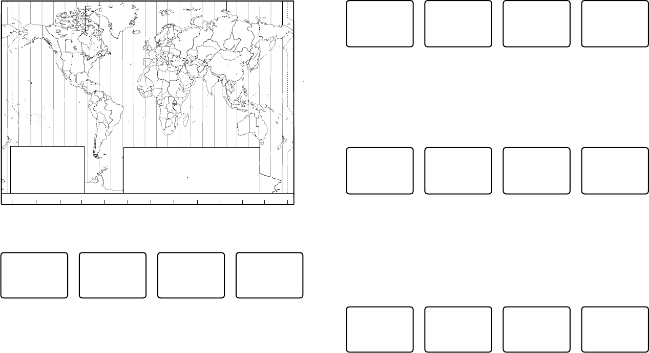
1. Work out the time difference between UTC and your local time (from the following
graphic).
2. Select GPS/DATA then SETTING.
3. Select TIME OFFSET to enter the difference between UTC and local time. Use the
Channel Select knob or + or – to change the time. Half hour increments can be used
with a maximum offset of ±13 hours.
4. Press ENT when the local time is correct.
LOC is displayed after the time on the LCD as a reminder that local time is selected.
3-4-2 Set local sensitivity
MENU SELECT
BACKLIGHT ▲
BUDDY LIST
►LOCAL/DIST
CONTRAST ▼
SENSITIVITY
DISTANT
►LOCAL
1. Select LOCAL/DIST then scroll to LOCAL.
2. Press ENT to activate the LOCAL setting. This disables distance sensitivity and the menu
is displayed again.
LOCAL
is displayed on the LCD as a reminder that sensitivity is reduced.
3-5 Set the contrast level (CONTRAST)
There are 8 levels of contrast.
MENU SELECT
BUDDY LIST▲
LOCAL/DIST
►CONTRAST
GPS/DATA ▼
CONTRAST
LO HI
PRESS ENT
1. Select CONTRAST.
2. Select a comfortable contrast level using the Channel Select knob or + or – on the
microphone to change the setting.
3. Press ENT to enable the setting and return to the menu.
3-6 GPS data and time (GPS/DATA)
If the boat has an operational GPS navigation receiver and is connected by NMEA port, the
VHF radio automatically detects and updates the vessel position and the local time.
However, if the GPS navigation receiver is disconnected or absent, you can specify the vessel
position and the local time manually, using the GPS/DATA option.
This information is important because it will be used if a DSC distress call is transmitted.
• If GPS data is NOT available for some reason, the NO GPS alert will sound for 5 seconds (or
until you press any key) and the radio requests you to enter the position data manually.
• This request is repeated every 4 hours if you do not enter the position data manually.
After you have entered the position data manually, you must update it within 23.5 hours
otherwise the NO GPS alert sequence repeats.
• The NO GPS warning will be shown whenever GPS data is not available from an operational
GPS navigation receiver.
Simrad - RS35 Operation InstructionsSimrad - RS35 Operation Instructions 2524
MENU SELECT
LOCAL/DIST▲
CONTRAST
►GPS/DATA
RADIO SETU▼
GPS/DATA
MANUAL
►SETTING
SETTING
TIME OFFSET
TIME FORMAT
►TIME DISPLY
LL DISPLY ▼
TIME DISPLY
►ON
OFF
1. Select GPS/DATA then SETTING.
2. Select TIME DISPLY.
3. Select ON (on) or OFF (off ) as desired. In this example, OFF has been selected and the
LCD no longer shows the time.
3-6-5 Position display options (LL DISPLY)
If your vessel position and time data are being updated through a GPS navigation receiver,
you can show or hide your vessel position on the LCD.
MENU SELECT
LOCAL/DIST▲
CONTRAST
►GPS/DATA
RADIO SETU▼
GPS/DATA
MANUAL
►SETTING
SETTING
TIME FORMAT
TIME DISPLY
►LL DISPLY
COG/SOG
LL DISPLY
►ON
OFF
1. Select GPS/DATA then SETTING.
2. Select LL DISPLY.
3. Select ON (on) or OFF (off ) as desired. In this example, OFF has been selected and the
LCD no longer shows the vessel position.
3-6-6 Course & speed display options (COG/SOG)
If your vessel position and time data are being updated through a GPS navigation receiver,
you can show or hide your course over ground (COG) and speed over ground (SOG) data on
the LCD.
MENU SELECT
LOCAL/DIST▲
CONTRAST
►GPS/DATA
RADIO SETU▼
GPS/DATA
MANUAL
►SETTING
SETTING
TIME DISPL▲
LL DISPLY
►COG/SOG
GPS ALERT
COG/SOG
ON
►OFF
1. Select GPS/DATA then SETTING.
2. Select COG/SOG.
3. Select ON (on) or OFF (off ) as desired. In this example, ON has been selected and so the
LCD shows the bearing and speed.
ZABC D F GHI
N
O
P
Q
R
S
T
U
WE
STANDARD TIME ZONES
Corrected to January 2011
Zone boundaries are approximate
Daylight Saving Time (Summer Time),
usually one hour in advance of Standard
Time, is kept in some places
Map outline © Mountain High Maps
Compiled by HM Nautical Almanac Office
V
XKL
P
Q
Q
R
V
UT
S
R
Q
P*
T
S
A
A
Z
B
C
Z
AB
B
B
C
S
S
S
R
HI* K
K
M
M
H
H
H
IK
F
G
E
D*
*
E*
*
C
CD
G
H
EF
H
I
G
C
E
KL
Z
Z
P
N
0° 30°E 60°E 90°E 120°E 150°E
30°W
60°W
90°W
120°W
150°W
180° 180°
L
Z
N
O
O
Z
Z
Z
C
D
D
E
F
E*
F*
K
L
*
*
L
LM
M
Q
O
Q
A
S
U
W
V*
A
Y
M
LM Y
P
K
H
M
XX
W
W
X
M*
W
M*M*
MM
L
M
M†
K
I
D
F
GI
I
I
K
L
L
Z
International Date Line
International Date Line
WORLD MAP OF TIME ZONES
R
C
B
B
A
P
R
I
C
R
Q
*
T
U
Q
§
§
W
M
E
†
M
K
C
G
G
H
I
I*
K
K*
– 7
– 8
– 9
– 9 30
–10
–10 30
L
L*
M
M
M*
M†
–11
–11 30
–12
–12 45
–13
–14
V
V*
W
X
Y
+ 9
+ 9 30
+10
+11
+12
hhhm
m
m
m
Z
A
B
C
C*
D
0
– 1
– 2
– 3
– 3 30
– 4
hm
E
E*
E†
F
F*
– 5 30
– 5 45
– 6
– 6 30
D*
– 4 30
– 5
N
O
P
P*
Q
+ 1
+ 2
+ 3
+ 3 30
+ 4
Q*
R
S
T
U
+ 4 30
+ 5
+ 6
+ 7
+ 8
Standard Time = Universal Time – value from table
h
No Standard Time legally adopted
Universal Time = Standard Time + value from table
hh
m m
§
3-6-3 Time format options (TIME FORMAT)
Time can be shown in 12 or 24 hour format.
MENU SELECT
LOCAL/DIST▲
CONTRAST
►GPS/DATA
RADIO SETU▼
GPS/DATA
MANUAL
►SETTING
SETTING
TIME OFFSET
►TIME FORMAT
TIME DISPLY
LL DISPLY ▼
TIME FORMAT
►12 Hr
24 Hr
06:56PM LOC
1. Select GPS/DATA then SETTING.
2. Select TIME FORMAT.
3. Select 12 or 24 hr as desired. In this example, 12 hour format has been selected and so
the LCD shows the AM or PM suffix.
3-6-4 Time display options (TIME DISPLY)
If your vessel position and time data are being updated through a GPS navigation receiver,
you can show or hide the time on the LCD.
Simrad - RS35 Operation InstructionsSimrad - RS35 Operation Instructions 2726
Section 4 - Radio setup menu (RADIO SETUP)
Hold down CALL/MENU key for about 1 second to access the following RADIO SETUP
options.
The following menu options are explained in this section.
RADIO SETUP UIC * Section 4-1
CH NAME Section 4-2
RING VOLUME Section 4-3
KEY BEEP Section 4-4
UNITS Section 4-5
INT SPEAKER Section 4-6
WATCH MODE * Section 4-7
WX ALERT * TONE ALERT Section 4-8-1
SAME ALERT Section 4-8-2
SAME CODE Section 4-8-5
COM PORT Section 4-9
GPS SOURCE Section 4-10
FAV CH SETUP * Section 4-11
* Model dependant
See sections 1-3 and 1-4 if you want to know how to move around the menu and enter, save
and change data.
4-1 Channel (UIC)
US and AUS models only.
Toggle between USA, International, or Canadian channel banks. The selected channel bank
is displayed on the LCD along with the last used channel. All the channel charts are shown in
Appendix C.
RADIO SETUP
►UIC
CH NAME
RING VOLUME
KEY BEEP ▼
UIC
►USA
INT L
CANADA
1. Select RADIO SETUP then UIC.
2. Select the desired channel bank then press ENT.
4-2 Channel names (CH NAME)
The channel charts are listed in Appendix C with their default name tags. CH NAME gives you
the option to edit or delete the channel name tags displayed on the LCD.
In this example, the channel name tag PHONE-PORTOP associated with channel 87 is being
changed to CALL PORT OP.
3-6-7 GPS alert (GPS ALERT)
If the GPS Alert is ON and the GPS navigation receiver is disconnected, the alarm sounds.
Note: The default setting is ON for the RS35 EU and OFF for the RS35 US.
MENU SELECT
LOCAL/DIST▲
CONTRAST
►GPS/DATA
RADIO SETU▼
GPS/DATA
MANUAL
►SETTING
SETTING
TIME DISPL▲
LL DISPLY
COG/SOG
►GPS ALERT
GPS ALERT
►ON
OFF
1. Select GPS/DATA then SETTING.
2. Select GPS ALERT.
3. Select ON (on) or OFF (off ) as desired.
3-7 GPS simulator (GPS SIM)
The GPS simulator is set to OFF whenever the radio is turned ON or whenever real GPS data
is available through the COM port. (The GPS simulator will not operate if a GPS signal is
received).
However, if you want to test it, turn it ON. Note that DSC transmissions will be blocked while
the GPS simulator is ON.
MENU SELECT
RADIO SETU▲
DSC SETUP
AIS SETUP
►GPS SIM ▼
GPS SIM
ON
►OFF
1. Select GPS SIM.
2. Select ON (on) or OFF (off ) as desired.
3-8 Reset to factory defaults (RESET)
Use this to return every setting to the factory defaults except all MMSI settings and the
entries in your buddy list.
MENU SELECT
DSC SETUP ▲
AIS SETUP
GPS SIM
►RESET
RESET RADIO
ARE YOU SURE
YES
►NO
1. Select RESET. The radio asks for confirmation.
2. Select YES then press ENT to confirm and reset the radio. The menu is displayed again.
Simrad - RS35 Operation InstructionsSimrad - RS35 Operation Instructions 2928

RADIO SETUP
UIC
►CH NAME
RING VOLUME
KEY BEEP ▼
CH NAME
PHONE-PORTOP
PHONE-PORTOP
►EDIT
DELETE
EDIT CH NAME
PHONE-PORTOP
SAVE CH NAME
CALL PORTOP
►YES
NO
63
1. Select RADIO SETUP then CH NAME. Use the Channel Select knob or + or - to step
through the channel name tags until you see the one you want to change then press
ENT.
2. To delete the channel name, select DELETE and press ENT.
3. To edit the channel name, select EDIT to edit the existing name tag.
4. Input the new name over the existing name. It can be a maximum of 12 characters.
5. Press ENT (repeatedly is necessary) to display the YES/NO confirmation.
6. Press ENT to confirm the new channel name tag (or the deletion).
7. Press EXIT to return to the CH NAME screen.
4-3 Ring volume (RING VOLUME)
The radio sounds the friendly two-tone alert when it detects an incoming DSC call. You can
change the volume level.
RADIO SETUP
UIC
CH NAME
►RING VOLUME
KEY BEEP ▼
RING VOLUME
►HIGH
LOW
1. Select RADIO SETUP then RING VOLUME.
2. Select HIGH (loud) or LOW (soft) then press ENT.
4-4 Key beep volume (KEY BEEP)
You can change the key beep volume or turn the key beeps off completely.
RADIO SETUP
CH NAME ▲
RING VOLUME
►KEY BEEP
UNITS ▼
KEY BEEP
HIGH
►LOW
OFF
Simrad - RS35 Operation InstructionsSimrad - RS35 Operation Instructions 3130
1. Select RADIO SETUP then KEY BEEP.
2. Select the desired setting then press ENT.
4-5 Select units (UNITS)
You can select your preferred measurement units for distance and cross track error (for
waypoint navigation).
RADIO SETUP
RING VOLUM▲
KEY BEEP
►UNITS
INT SPEAKE▼
UNITS
►METRIC
NAUTICAL
STATUTE
1. Select RADIO SETUP then UNITS.
2. Select your preferred measurement units then press ENT.
Note: Nautical Miles is the only unit used in AIS mode.
4-6 Internal speaker connections (INT SPEAKER)
You can switch the radio’s internal speaker ON or OFF. The external speaker is always ON if a
speaker is plugged into the external speaker jack.
RADIO SETUP
KEY BEEP ▲
UNITS
►INT SPEAKER
WATCH MODE▼
INT SPEAKER
►ON
OFF
1. Select RADIO SETUP then INT SPEAKER.
2. Select ON (on) or OFF (off ) then press ENT to enable the setting and return to the menu.
4-7 Set the priority channel (WATCH MODE)
US model only.
If you are operating on the USA or Canadian channel banks, you can set the priority channel
to cover both CH16 and CH09 as well as the working channel, similar to a TRI WATCH.
RADIO SETUP
UNITS ▲
INT SPEAKER
►WATCH MODE
WX ALERT ▼
WATCH MODE
►ONLY 16
16CH + 9CH
1. Select RADIO SETUP then WATCH MODE.
2. Select the desired setting then press ENT.
Simrad - RS35 Operation InstructionsSimrad - RS35 Operation Instructions 3332
RADIO SETUP
INT SPEAKE▲
WATCH MODE
►WX ALERT
COM PORT ▼
TONE ALERT
►SAME ALERT
SAME CODE
SAME ALERT
ON
►OFF
1. Select RADIO SETUP then WX ALERT.
2. Select SAME ALERT.
3. Select ON to receive any local NWR or EAS alerts - the SAME ALERT symbol
SAME
will be displayed on the LCD or, to ignore these weather alerts, select OFF.
4-8-3 Receiving a SAME ALERT
If SAME ALERT alert is ON and an NWR or EAS alert for your geographic area is broadcast by
the NOAA NWR transmitters, the alert is picked up automatically and the alarm sounds.
Press any key to cancel the alarm.
If the alert is being sent by NOAA NWR, the radio automatically tunes to the designated
frequency so that you can listen to the alert.
If the alert is being sent by the EAS, the nature of the alert is shown on the LCD as WARNING,
WATCH, ADVISORY, or TEST.
Press any key to show the nature of the alert. (The list of alerts is shown in Appendix C.)
4-8-4 Receiving SAME TEST messages
In addition to the WARNING, WATCH and ADVISORY alerts, the EAS also send out TEST mes-
sages so that you can check your WX ALERT setup is working correctly. The TEST message is
usually transmitted between 1000 and 1200 (10.00AM and noon) every Wednesday.
Note: If there is a threat of severe weather, the test is postponed until the next good weather
day.
If your WX ALERT setup is working correctly, the alert sounds and TEST is displayed on the
LCD, followed by a broadcast message from the National Weather Service.
4-8-5 Enter a SAME CODE (County ID)
If you want to receive SAME weather alerts, you must enter and then Select a SAME code for
your geographic area into your radio. You can enter a maximum of 4 SAME codes (4 counties)
in your geographic area.
Telephone 1-888-NWR-SAME (1-888-697-7263) or visit www.nws.noaa.gov/nwr/indexnw.htm
to find the SAME codes for your geographic area (you must be within the United States of
America, Puerto Rico, the U.S. Virgin Islands and U.S. Pacific Territories).
4-8 Weather alerts (WX ALERT)
US model only.
Use WX ALERT to set your preferences for weather alert information.
The NOAA provides several weather forecast channels on USA and Canadian channel banks.
If severe weather such as storms or hurricanes are forecast, the NOAA broadcasts a weather
alert on 1050 Hz.
The NOAA All Hazards Weather Radio Service (NWR) works in conjunction with the
Emergency Alert System (EAS) to issue weather alerts for specific geographic areas or specific
weather conditions. It uses a digital encoding system known as SAME (Specific Area Message
Encoding) to broadcast these alerts.
Each transmitter in the NOAA All Hazards Weather Radio Service (NWR) network is identified
with a unique 6-digit SAME code. Each transmitter operates on one of 7 frequencies.
Note: To activate a SAME alert, a SAME CODE (county ID) must be selected and turned ON
(see section 4-8-2).
4-8-1 TONE ALERT
If TONE ALERT is ON and an alert tone of 1050 Hz is broadcast from the NOAA weather
station, the weather alert is picked up automatically and the alarm sounds. Press any key to
cancel the alarm and to hear the weather alert message.
RADIO SETUP
INT SPEAKE▲
WATCH MODE
►WX ALERT
COM PORT ▼
►TONE ALERT
SAME ALERT
SAME CODE
TONE ALERT
►ON
OFF
1. Select RADIO SETUP then WX ALERT.
2. Select TONE ALERT.
3. Select ON to hear any weather alerts on 1050 Hz - the TONE ALERT symbol will be
displayed on the LCD or, to ignore these weather alerts, select OFF.
4-8-2 SAME ALERT
Note: SAME ALERT works only after you have entered and selected a SAME code for your
geographic area (see Section 4-8-5 and 4-8-6).
Note: SCAN mode will operate up to 50% more slowly when SAME ALERT is ON to allow time
to decode the special warning code transmissions.

Simrad - RS35 Operation InstructionsSimrad - RS35 Operation Instructions 3534
4-9 NMEA protocol (COM PORT)
The COM PORT must be configured correctly before use. The radio can be added to a group
of instruments using NMEA protocol.
RADIO SETUP
WATCH MODE▲
WX ALERT
►COM PORT
GPS SOURCE▼
NMEA
CHECK SUM
►ON
OFF
1. Select RADIO SETUP then COM PORT.
2. Select the desired setting then press ENT.
CHECK SUM ON (on) is the usual setting.
The COM PORT uses 4800 baud rate and can receive the following GPS data sentences:
RMC, GGA, GLL, GNS. Additionally, the radio will output the following NMEA DSC data:
DSC (for DSC call), DSE (for enhanced position).
4-10 Select the GPS source (GPS SOURCE)
This radio can use either NMEA 0183 or NMEA 2000 protocol to receive GPS data from a
compatible GPS unit.
Note: NMEA 2000 SOURCE options will appear (up to 4 sources showing the actual source
name) only if an NMEA 2000 network is connected to the radio and is operational.
RADIO SETUP
WX ALERT ▲
COM PORT
►GPS SOURCE
FAV CH SETU
GPS SOURCE
►NMEA0183
LGC3000
LCX113CHD
1. Select RADIO SETUP then GPS SOURCE. (If there is only one NMEA protocol available on
your vessel, only that will be shown).
2. Select the desired NMEA source then press ENT.
4-11 Favourite channel setup - Wx key (FAV CH SETU)
EU and AUS models only.
The Wx key can be programmed to a weather channel of your choice so that you have quick
access to that channel.
1. Select RADIO SETUP then FAV CH SETU.
2. Rotate the CH knob or press UP/DOWN key to select a channel that you want to save it as
the WX favorite channel, then press ENT to save with WX icon lighting to indicate.
RADIO SETUP
INT SPEAKE▲
WATCH MODE
►WX ALERT
COM PORT ▼
WX ALERT
TONE ALERT
SAME ALERT
►SAME CODE
SAME CODE
►NEW CODE
INPUT SAME
CODE
SAME CODE
012011
►STORE
CANCEL
SAME CODE
►NEW CODE
0122003
1. Select RADIO SETUP then WX ALERT.
2. Select SAME CODE. If you have already entered any SAME codes, they are listed on the
LCD.
3. Select NEW CODE. Enter the new SAME code along the dashed line, one number at a
time. Press ENT to confirm each correct entry and to move to the next digit.
If you make an error, press – until < appears, then press ENT to backup and correct the
entry.
4. Press ENT to store the SAME code.
5. Repeat if necessary to enter a maximum of 10 SAME codes.
4-8-6 Select a working SAME code
You must select a SAME code for your geographic working area that you have previously
entered into the radio in order to receive SAME weather alerts:
RADIO SETUP
INT SPEAKE▲
WATCH MODE
►WX ALERT
COM PORT ▼
WX ALERT
TONE ALERT
SAME ALERT
►SAME CODE
SAME CODE
NEW CODE
►012203
017093
012203
EDIT
DELETE CODE
►SELECT CODE
SELECT CODE
012203
►YES
NO
1. Select RADIO SETUP then WX ALERT.
2. Select SAME CODE. If you have already entered any SAME codes, they are listed on the
LCD.
3. Select the SAME# for your geographic area (0122003 in the above example) and press ENT.
4. Choose SELECT CODE. Then select YES.
USER MMSI
876543210
►STORE
CANCEL
DSC SETUP
►USER MMSI
GROUP SETUP
ATIS MMSI
ATIS SELEC▼
VIEW MMSI
876543210
1. Select DSC SETUP, then USER MMSI.
If you have already entered your MMSI, it is shown on the LCD.
2. If this is the rst time that you are entering your MMSI, a dashed line appears.
Enter your MMSI along the dashed line, one number at a time. Press ENT to confirm
each correct entry and to move to the next digit.
If you make an error, press – until < appears, then press ENT to backup and correct the
entry.
3. Press ENT to store your user MMSI.
4. Enter your user MMSI again as a password check, then press ENT to permanently store
the user MMSI and return to the menu.
5. You can view your stored user MMSI at anytime by selecting USER MMSI in the main
menu.
5-2 Maintain your groups
Use GROUP SETUP to create, edit, or delete 1, 2, or up to 20 groups of frequently called
people stored in alphanumeric order. A group MMSI always starts with 0.
5-2-1 Create a group (GROUP SETUP)
DSC SETUP
USER MMSI
►GROUP SETUP
ATIS MMSI
ATIS SELEC▼
GROUP SETUP
MANUAL NEW
GROUP NAME
GROUP MMSI
0
FISHING 1
012345678
►STORE
CANCEL
1. Select DSC SETUP then GROUP SETUP.
2. Select MANUAL NEW.
3. If this is the rst time that you are entering a group name, a dashed line appears
4. Enter the group name along the dashed line. It can be a maximum of 12 alphanumeric
characters. Press ENT to confirm each correct entry and to move to the next position.
If you make an error, press – until < appears, then press ENT to backup and correct the
entry.
5. Enter the group MMSI. (Note that the first number is always a 0.) Press ENT.
6. The group name and group MMSI are shown in a confirmation screen. Press ENT to
store the details and return to the GROUP SETUP screen.
Section 5 - DSC setup menu (DSC SETUP)
WARNING
A valid USER MMSI must be entered into the radio before these DSC functions can be
used. See Section 5-1 for instructions on entering your USER MMSI.
Hold down CALL/MENU key for about 1 second to access the following DSC SETUP options.
The following menu options are explained in this section.
DSC SETUP USER MMSI Section 5-1
GROUP SETUP Section 5-2
ATIS MMSI (EU only) Section 5-3
ATIS SELECT (EU only) Section 5-4
INDIV REPLY Section 5-5
DSC FUNC Section 5-6
LL REPLY Section 5-7
AUTO SWITC Section 5-8
TEST REPLY Section 5-9
TIMEOUT Section 5-10
See sections 1-3 and 1-4 if you want to know how to move around the menu and enter, save
and change data.
5-1 Enter or view your USER MMSI (USER MMSI)
This is a once-only operation. You must enter your user MMSI before you can access the DSC
functions.
You can display and read your user MMSI at any time, but you get only one opportunity to
enter your user MMSI.
The user MMSI (Marine Mobile Service Identity) is a unique 9 digit number, similar to a
personal telephone number. It is used on marine transceivers that are capable of using DSC
(Digital Select Calling).
Contact the appropriate authorities in your country to obtain your user MMSI. If you are
unsure who to contact, consult your Simrad dealer.
DSC SETUP
►USER MMSI
GROUP SETUP
ATIS MMSI
ATIS SELEC▼
INPUT USER
MMSI
USER MMSI
876543210
►STORE
CANCEL
USER MMSI
INPUT AGAIN
Simrad - RS35 Operation InstructionsSimrad - RS35 Operation Instructions 3736

DSC SETUP
USER MMSI
GROUP SETUP
►ATIS MMSI
ATIS SELEC▼
INPUT ATIS
MMSI
9
ATIS MMSI
9987654321
►STORE
CANCEL
ATIS MMSI
INPUT AGAIN
9
ATIS MMSI
9987654321
►STORE
CANCEL
2. If this is the rst time that you are entering your ATIS MMSI, a dashed line appears.
Enter your ATIS MMSI along the dashed line. The first number is always 9. Press ENT to
confirm each correct entry and to move to the next digit.
If you make an error, press – until < appears then press ENT to backup and correct the
entry.
3. Press ENT to store the ATIS MMS.
4. Enter your ATIS MMSI again as a password check, then press ENT to permanently store
the ATIS MMSI and return to the menu.
5. You can view your stored ATIS MMSI at any time by selecting ATIS MMSI in the main
menu.
5-4 Enable ATIS functionality (ATIS SELECT)
EU models only.
ATIS functionality will operate only after the ATIS MMSI has been entered (see previous section).
When ATIS functionality is enabled, the ATIS symbol
ATIS
is shown on the LCD.
DSC SETUP
GROUP SETUP
ATIS MMSI
►ATIS SELECT
INDIV REPL▼
ATIS SELECT
►ON
OFF
1. Select DSC SETUP then ATIS SELECT.
2. Select OFF to disable ATIS functionality or select ON to enable the ATIS functionality -
DSC must be turned off first.
3. Press ENT to confirm.
Note: It is not possible to have both ATIS ON (on) and DSC ON (on) simultaneously. If you
want to activate ATIS, you must first switch DSC off. A warning will remind you if DSC is
already ON.
5-2-2 Edit or delete a group name or group MMSI (GROUP SETUP)
You can edit a group name or group MMSI at any time.
DSC SETUP
USER MMSI
►GROUP SETUP
ATIS MMSI
ATIS SELEC▼
GROUP SETUP
MANUAL NEW
►FISHING 1
SAILING
FISHING 1
012345678
►EDIT
DELETE
EDIT NAME
FISHING 1
ENTER MMSI
012345678
FISHING 1
012345678
►STORE
CANCEL
1. Select DSC SETUP then GROUP SETUP. The existing group names are displayed.
2. Select the group you want to edit. Press ENT.
3. To delete the group, select DELETE then YES. The group is deleted immediately and the
group list is displayed again.
4. To edit the group, select EDIT.
5. Edit the group name OR to edit only the MMSI, press ENT repeatedly until the cursor
moves to the MMSI line.
6. When you are finished, press ENT (repeatedly if necessary) until a new LCD appears.
7. Press ENT to store the changes and return to the GROUP SETUP screen.
5-3 Enter or check your ATIS MMSI (ATIS MMSI)
EU models only.
You must enter your ATIS MMSI to access ATIS functionality if you are navigating inland
waterways within Europe.
• ATIS sends a digital message any time that you release the PTT key. Inland waterways
rules require 1 W Tx power on Channels 06, 08, 10, 11, 12, 13, 14, 15, 17, 71, 72, 74, and 77.
• An ATIS MMSI always starts with the number 9
• This is a once-only operation. You must enter your ATIS MMSI before you can access the
ATIS functions
• You can display and read your ATIS MMSI at any time, but you get only one opportunity
to enter your ATIS MMSI.
1. Select DSC SETUP then ATIS MMSI.
If you have already entered your ATIS MMSI, it is shown on the LCD.
Simrad - RS35 Operation InstructionsSimrad - RS35 Operation Instructions 3938
5-7 Response type to LL polling calls (LL REPLY)
You can set up the radio to respond to an LL polling request in one of three ways:
• MANUAL reply manually to any incoming LL polling requests from your buddies.
• AUTO automatically replies to any incoming LL polling requests from any of
your buddies.
• OFF ignores all incoming buddy LL polling requests.
DSC SETUP
INDIV REPL▲
DSC FUNC
►LL REPLY
AUTO SWITC▼
LL REPLY
►MANUAL
AUTO
OFF
1. Select DSC SETUP then LL REPLY.
2. Select your response and press ENT to confirm and return to the menu.
5-8 Automatic channel switching (AUTO SWITCH)
When a DSC call is received, it may include a request to change to a specific channel for
subsequent communications. If a channel switch request is included, your options are:
• allow the radio to switch to the requested channel immediately by pressing the ENT
button, or
• do nothing to allow the radio to automatically switch to the requested channel after a
delay of 10 seconds, or
• cancel the automatic switch and remain on the current channel by pressing the EXIT button.
However, automatic switching to a subsequent communications channel on receipt of a DSC
call might in some cases disrupt important ongoing communications if the working channel
changes without the operator knowing.
You can prevent the radio from automatically switching from the current working channel by
setting the AUTO SWITCH feature to OFF.
If the AUTO SWITCH feature is set to OFF, an
X
will be displayed on the LCD to remind you
that this feature is set to off. Additionally, the text “AUTO SW OFF” will be included in an All
Ships or Group call replacing the text “AUTO CHxx”
DSC SETUP
DSC FUNC ▲
LL REPLY
►AUTO SWITC
TEST REPLY▼
AUTO SWITCH
►ON
OFF
1. Select DSC SETUP, then AUTO SWITCH.
2. Select ON (on) to enable automatic channel switching.
3. Select OFF (off) to disable automatic channel switching.
5-5 Response to individual calls (INDIV REPLY)
You can respond to incoming individual calls with an automatic response or with a manual
response.
An automatic response sends an acknowledgement and then sets the request link channel,
ready for a conversation.
A manual response asks if you want to acknowledge the call, and then asks if you want to
converse with the caller.
1. Select DSC SETUP, then INDIV REPLY.
2. Select AUTO for an automatic response, or MANUAL for a manual response.
3. Press ENT to confirm your choice and return to the menu.
DSC SETUP
GROUP SETU▲
ATIS MMSI
ATIS SELECT
►INDIV REPL▼
INDIV REPLY
MANUAL
►AUTO
5-6 Enable DSC functionality (DSC FUNC)
DSC functionality will operate only after a valid USER MMSI has been entered - see 5-1.
When DSC functionality is selected, the DSC symbol
DSC
is shown on the LCD.
DSC SETUP
ATIS MMSI ▲
ATIS SELECT
INDIV REPLY
►DSC FUNC ▼
DSC FUNC
►ON
OFF
1. Select DSC SETUP then DSC FUNC.
2. Select OFF to disable DSC functionality or s
elect ON to enable the DSC functionality
- ATIS
(if applicable) must be turned off first.
Note: Disabling DSC functionality is not recommended.
3. Press ENT to confirm.
Note: It is not possible to have both ATIS ON (on) and DSC ON (on) simultaneously. If you
want to activate DSC, you must first switch ATIS off. A warning will remind you if ATIS is
already ON.
Simrad - RS35 Operation InstructionsSimrad - RS35 Operation Instructions 4140
Section 6 - AIS setup menu (AIS SETUP)
Hold down CALL/MENU key for about 1 second to access the following AIS SETUP options.
The following menu options are explained in this section.
AIS SETUP AIS FUNC Section 6-1
AIS DISPLAY Section 6-2
BAUD RATE Section 6-3
GPS REDIR Section 6-4
CPA ALARM Section 6-5
CPA Section 6-6
TCPA Section 6-7
5-9 DSC Test Reply (TEST REPLY)
You can respond to incoming DSC TEST calls with an automatic response or with a manual
response.
• MANUAL manual response is required, press ENT to confirm or press EXIT to cancel.
• AUTO automatically replies after a 10 second delay with an ACK to any incoming
DSC TEST call.
DSC SETUP
LL REPLY ▲
AUTO SWITC
►TEST REPLY
TIMEOUT
TEST REPLY
►AUTO
MANUAL
5-10 Set the inactivity timer (TIMEOUT)
You can set the inactivity timer with the following options:
• AUTOMATED you can set the inactivity timer to automatically timeout after a
period of inactivity for the following two categories: NON-DISTRESS or
DISTRESS.
Timeout options are:
DISTRESS: NO TIMEOUT; 5 MINS; 10 MINS (default is NO TIMEOUT)
NON-DISTR: NO TIMEOUT; 10 MINS; 15 MINS (default is 15 MINS)
• NON AUTO you can set the inactivity timer to exit any non-automated procedure
activity.
Timeout options are:
NO TIMEOUT; 10 MINS; 15 MINS (default is 10 MINS)
Note: If NO TIMEOUT is selected, then you must press the EXIT key to exit the procedure.
Example: to set a 10 minute TIMEOUT for non-automated functions:
1. Select TIMEOUT, then select NON AUTO
2. Select desired timeout period: NO TIMEOUT, 10 MINS or 15 MINS
NON AUTO
NO TIMEOUT
►10 MINS
15 MINS
TIMEOUT
►AUTOMATED
NON AUTO
DSC SETUP
LL REPLY ▲
AUTO SWITC
TEST REPLY
►TIMEOUT
In this example, 10 MINS has been selected, meaning the radio will exit any non-automated
procedure after a period of 10 minutes of non-activity.
Simrad - RS35 Operation InstructionsSimrad - RS35 Operation Instructions 4342
See sections 1-3 and 1-4 if you want to know how to move around the menu and enter, save
and change data.
6-1 Enable AIS functionality (AIS FUNC)
The AIS function can be turned ON or OFF. When AIS functionality is selected, the AIS symbol
AIS
is shown on the LCD.
AIS SETUP
►AIS FUNC
AIS DISPLAY
BAUD RATE
GPS REDIR
AIS FUNC
►ON
OFF
6-2 AIS data display format (AIS DISPLAY)
When viewing the AIS plotter screen, AIS targets can be displayed with the vessels name or
the vessels MMSI.
AIS SETUP
►AIS DISPLAY
BAUD RATE
GPS REDIR
CPA ALARM
AIS DISPLAY
►SHIP MMSI
SHIP NAME
6-3 AIS baud rate (BAUD RATE)
AIS data can be output to a compatible chart-plotter / MFD or PC via the NMEA port. The
NMEA port baud rate can be set to 4800 or 38400. The default setting is 38400. If 4800 is
selected, a warning that data may be lost is displayed.
AIS SETUP
►BAUD RATE
GPS REDIR
CPA ALARM
CPA
AIS SETUP
38400
►4800
AIS INFO
MAY BE LOST!
►NO
YES
6-4 GPS redirection (GPS REDIR)
GPS redirection option set to output the GPS information to the chartplotter eliminating the
need for an additional multiplexer.
If “yes” is selected, the string $RMC will be redirected to the chartplotter once it is received.
Note: The REDIR function will only redirect RMC and GLL messages from NMEA 0183 input
port to the AIS output port.
AIS SETUP
►GPS REDIR
CPA ALARM
CPA
TCPA
GPS REDIR
►NO
YES
6-5 Closest point of approach alarm (CPA ALARM)
Enables the CPA alarm. If set to OFF, there will be no T/CPA alarms regardless of the settings.
AIS SETUP
GPS REDIR
►CPA ALARM
CPA
TCPA
CPA ALARM
►ON
OFF
6-6 Closest point of approach settings (CPA)
CPA is the minimum distance between you and a target vessel based on the current speed
and course. You can set the minimum distance for CPA alarm to sound (1 NM to 30 NM).
Rotate the dial to set the CPA distance in 1 NM increments. Press ENT when done.
AIS SETUP
GPS REDIR
CPA ALARM
►CPA
TCPA
CPA
►01NM
6-7 Time to closest point of approach (TCPA)
TCPA is the minimum time of intercept between you and a target vessel based on the current
speed and course. Set the minimum time for the TCPA alarm to sound (5 Min to 30 Min).
Rotate the dial to set the TCPA time in 30 sec increments. Press ENT when done.
AIS SETUP
GPS REDIR
CPA ALARM
CPA
►TCPA
TCPA
►05:00Min
Section 7 - Wireless handset setup menu (HS SETTING)
Hold down CALL/MENU key for about 1 second to access the following HS SETTING options.
The following menu options are explained in this section.
HS SETTING SUBSCRIBE Section 7-1
REGISTERED HS Section 7-2
See sections 1-3 and 1-4 if you want to know how to move around the menu and enter, save
and change data.
7-1 Register a wireless handset (SUBSCRIBE)
Before a HS35 wireless handset can be used with the RS35 radio, it must be registered (paired)
with the radio through the subscription process.
HS SETTING
►SUBSCRIBE
REGISTERD HS
SUBSCRIBE
►YES
NO
SUBSCRIBE
WAITING
EXIT->QUIT
SUBSCRIBE
HS SUBSCRIBE
SUCCESSFUL!
EXIT->QUIT
1. Ensure the HS35 that you want to subscribe is charged and turned OFF.
Note: If you have another HS35 that is already subscribed to the RS35, ensure it remains o
during this proceedure.
On the RS35 base station radio:
2. Select HS SETTING, then SUBSCRIBE.
3. Select YES. The radio will display WAITING.
On the HS35 wireless handset:
4. Turn ON the HS35 that you want to subscribe to the RS35, the display will show
SEARCHING.
5. Press SCAN key until the display shows REGISTER.
6. The display will soon show CONNECTING, and then the HS35 will be paired to the RS35.
7-2 Delete a registered wireless handset (REGISTERED HS)
1. To delete an already registered handset, select REGISTERED HS
2. Select the handset you wish to remove and press ENT and then YES.
HS SETTING
SUBSCRIBE
►REGISTERD HS
REGISTERED HS
►CLEAR HS1
CLEAR HS2
CLEAR HS1
►YES
NO
Simrad - RS35 Operation InstructionsSimrad - RS35 Operation Instructions 4544
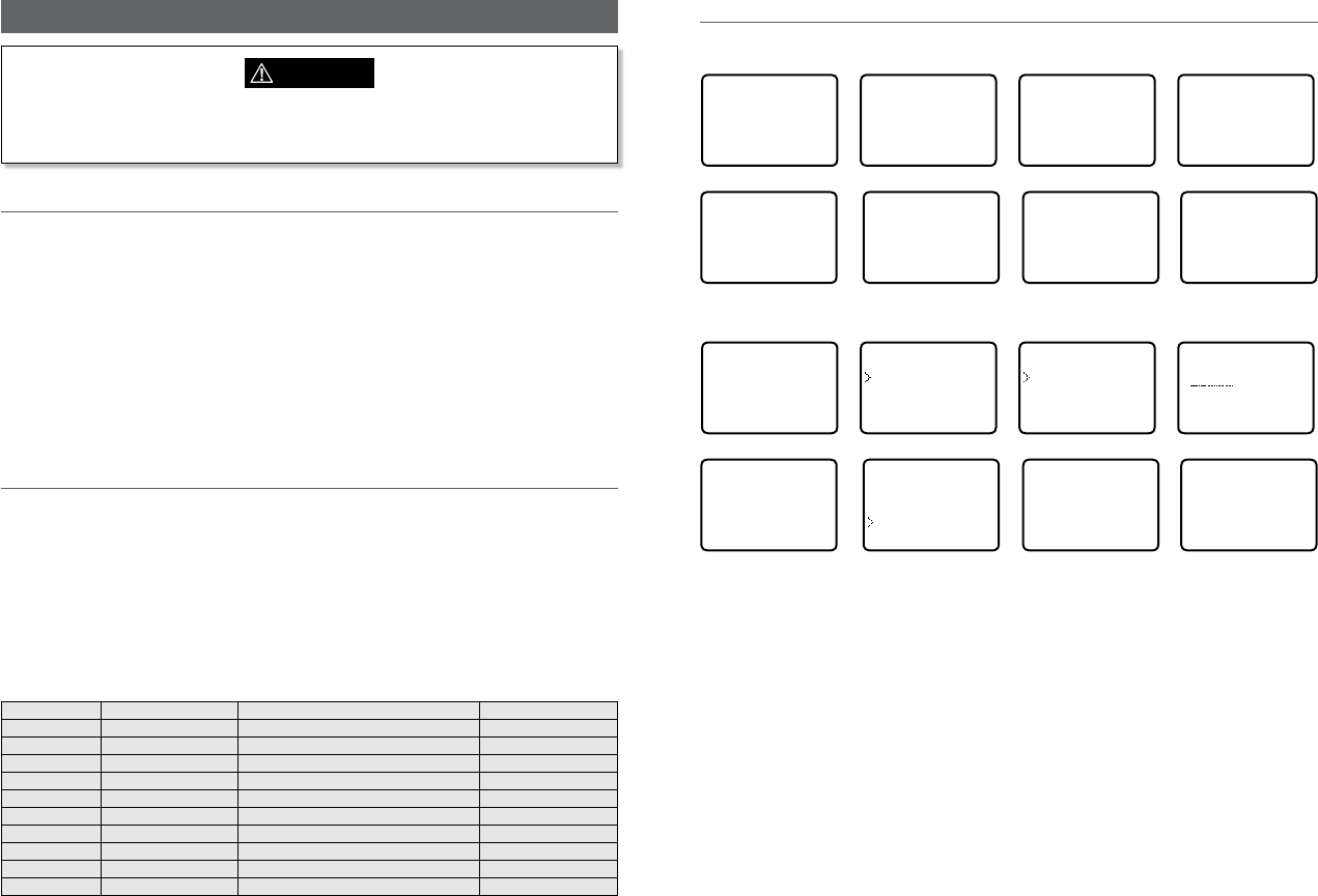
Section 8 - Sending and receiving DSC Calls
WARNING
A valid USER MMSI must be entered into this radio before these DSC functions can be
used. See section 5-1.
8-1 What is DSC?
DSC (Digital Selective Calling) is a semi-automated method of establishing VHF, MF, and HF
radio calls. It has been designated as an international standard by the IMO (International
Maritime Organization) and is part of the GMDSS (Global Maritime Distress and Safety
System).
Currently, you are required to monitor Distress Channel 16, but DSC will eventually replace
listening watches on distress frequencies and will be used to broadcast routine and urgent
maritime safety information.
DSC enables you to send and receive calls from any vessel or coast station that is equipped
with DSC functionality and within geographic range. Calls can be categorized as distress,
urgency, safety, or routine, and DSC selects a working channel automatically.
8-2 Sending DSC Calls
You can call any other person that has another DSC equipped radio.
• Quick press the CALL / MENU key to access the following DSC CALL menu options – select
LAST CALL to quickly call back the person who called you.
• Note that only four DSC CALL menu options can be shown on the LCD at any one time.
• Press + or – on the microphone or turn the Channel Select knob on the base station to
scroll up or down through the menu until the cursor is positioned at the desired option.
Press ENT (the center of the Channel Select knob) to display that option.
The following options are available:
DSC CALL INDIVIDUAL Make a DSC Call Section 8-3
LAST CALL Repeat the last DSC Call Section 8-5
GROUP Make a Group DSC Call Section 8-6
ALL SHIPS Make an All Ships DSC Call Section 8-7
CALL LOG View DSC Call Log Section 8-8
DISTR LOG View DSC Distress Log Section 8-9
SENT CALL View DSC Sent Call Log Section 8-10
LL REQUEST Request a position report Section 8-11
TRACK BUDDY Automatically track Buddy’s Section 8-12
DSC TEST Make a DSC Test Call Section 8-13
MMSI/GPS View MMSI and GPS information Section 8-14
8-3 Send an individual call (INDIVIDUAL)
Call to a Buddy
DSC CALL
►INDIVIDUAL
LAST CALL
GROUP
ALL SHIPS ▼
INDIVIDUAL
►ROUTINE
SAFETY
URGENCY
INDIVIDUAL
MANUAL NEW
►MERMAID IV
SEAROSE
CHOOSE CH
►INTER-SHIP
MANUAL
MERMAID IV
INDIVIDUAL
ROUTINE
►SET INTER
MERMAID IV
INDIVIDUAL
ROUTINE
►SEND?
MERMAID IV
INDIVIDUAL
ROUTINE
WAIT.. 00:00
INDIVIDUAL
ROUTINE
ACK FROM
MERMAID IV
▼ 00:00
Call to others
DSC CALL
►INDIVIDUAL
LAST CALL
GROUP
ALL SHIPS ▼
INDIVIDUAL
ROUTINE
SAFETY
URGENCY
INDIVIDUAL
MANUAL NEW
MERMAID IV
SEAROSE
MANUAL MMSI
0
CHOOSE CH
►INTER-SHIP
MANUAL
678912345
INDIVIDUAL
ROUTINE
SEND?
678912345
INDIVIDUAL
ROUTINE
CALLING...
678912345
INDIVIDUAL
ROUTINE
WAIT.. 00:00
1. Select DSC CALL then INDIVIDUAL.
2. Select the priority level: ROUTINE, SAFETY, URGENCY.
3. Select the buddy you want to call from your buddy list - or Select MANUAL NEW then
enter the MMSI of the individual you want to call and press ENT.
4. Choose a working channel to talk on. Select the INTER-SHIP and press ENT. The radio
automatically lists all Inter-ship (Simplex) channels that can be used. Duplex channels
cannot usually be called, however, If you wish to use a Duplex channel, select MANUAL
instead, then select your channel of choice. If the call is to a Coast Station (MMSI begins
with 00) the radio will recognize this and specify the correct channel to talk on.
5. Press ENT to SEND the call. Channel 70 is selected automatically and the Tx symbol is
shown on the LCD while the call is being sent.
6. The radio waits for an acknowledgement (WAIT). If the call is acknowledged (INDIV ACK)
press PTT to talk. Rotate the Channel Select knob to view additional options.
7. If there is no reply (UNABLE TO ACKNOWLEDGE) a message asks if you want to retry
(SEND AGAIN?). Press ENT to retry the call.
Simrad - RS35 Operation InstructionsSimrad - RS35 Operation Instructions 4746

8-4 Acknowledgement of an individual incoming call (INDIV)
When an incoming call is received, the alarm sounds for 2 minutes and INDIVIDUAL is
displayed.
123456789
NO AUTO SW
CH12 REQUEST
12:45 UTC
▲ 00:03
ROUTINE FROM
123456789
NO AUTO SW
CH12 REQUEST
▲▼ 00:02
INDIVIDUAL
ROUTINE FROM
123456789
NO AUTO SW
▼ 00:01
1. Press SILENC softkey (AIS/IC key) to silence the alert.
2. Press +/- button or rotate the CH knob to scroll any further information about the call.
3. Press NEW-CH softkey (AIS/IC key) to request a different working channel, or press
ABLE softkey (WX/NAV key) to acknowledge the call.
4. Or press EXIT to return to standby.
8-5 Reply to the Last Call (LAST CALL)
This facility is useful and used frequently.
DSC CALL
INDIVIDUAL
►LAST CALL
GROUP
ALL SHIPS ▼
SEAROSE
INDIVIDUAL
ROUTINE
10:22AM LOC
CHOOSE CH
►INTER-SHIP
MANUAL
SEAROSE
INDIVIDUAL
ROUTINE
►SEND?
1. Select DSC CALL then LAST CALL.
2. The contact details of the most recent incoming call are displayed. Press ENT.
3. Choose a working channel to talk on. Select the INTER-SHIP and press ENT. The radio
automatically lists all Inter-ship (Simplex) channels that can be used. Duplex channels
cannot usually be called, however, If you wish to use a Duplex channel, select MANUAL
instead, then select your channel of choice. If the call is to a Coast Station (MMSI begins
with 00) the radio will recognize this and specify the correct channel to talk on.
4. The call details are shown. Press ENT to send the call. The Tx symbol is displayed on the
LCD while the call is being sent.
5. If the call is acknowledged (INDIV ACK) press PTT to talk. If there is no reply a message
asks if you want to retry (SEND AGAIN?). Press ENT to retry the call.
8-6 Send a group call (GROUP)
You must already have stored a GROUP MMSI before making the call - see Section 5-2. Group
calls are always sent with ROUTINE priority.
DSC CALL
INDIVIDUAL
►LAST CALL
GROUP
ALL SHIPS ▼
GROUP
►DIVE 1
DIVE 2
CHOOSE CH
►INTER-SHIP
MANUAL
DIVE 1
GROUP CALL
►SEND?
1. Select DSC CALL then GROUP.
The radio displays the names of your pre-programed groups.
2. Select the group that you want to call (the GROUP MMSI must be set before making the
call).
3. Choose a working channel to talk on. Select the INTER-SHIP and press ENT. The radio
automatically lists all Inter-ship (Simplex) channels that can be used. Duplex channels
cannot usually be called, however, If you wish to use a Duplex channel, select MANUAL
instead, then select your channel of choice.
4. The call details are shown. Press ENT to send the call. The Tx symbol is displayed on the
LCD while the call is being sent.
8-7 Send an all ships call (ALL SHIPS)
DSC CALL
LAST CALL ▲
GROUP
►ALL SHIPS
CALL LOG ▼
ALL SHIPS
►SAFETY
URGENCY
CHOOSE CH
►INTER-SHIP
MANUAL
ALL SHIPS
SAFETY
►SEND?
1. Select DSC CALL then ALL SHIPS.
2. Select one of the following call priorities:
• SAFETY To send safety information to all other vessels in range.
• URGENCY For use when a serious situation or problem arises that could lead to a
distress situation.
3. Choose a working channel to talk on. Select the INTER-SHIP and press ENT. The radio
automatically lists all Inter-ship (Simplex) channels that can be used. Duplex channels
cannot usually be called, however, If you wish to use a Duplex channel, select MANUAL
instead, then select your channel of choice.
4. The call details are shown. Press ENT to send the call. The Tx symbol is displayed on the
LCD while the call is being sent.
Simrad - RS35 Operation InstructionsSimrad - RS35 Operation Instructions 4948

When the call log is full, the oldest entry is overwritten.
8-8 Send using the call log (CALL LOG)
The Call Log contains the contact details for the 20 most recent incoming calls, so that you
can call any of them again quickly.
DSC CALL
GROUP ▲
ALL SHIPS
►CALL LOG
DISTR LOG ▼
11 12345678
INDIVIDUAL
ROUTINE
09:45 UTC
11 12345678
►CALL BACK
DELETE
SAVE MMSI
CHOOSE CH
►INTER-SHIP
MANUAL
12345678
INDIVIDUAL
ROUTINE
►SEND?
1. Select DSC CALL then CALL LOG.
2. The radio displays the contact details for the most recent incoming call as the first entry
(01) in the call log. In the example, the contact details for the 11th most recent call are
displayed. Press ENT to move to the next screen.
3. Press ENT again to confirm the call back.
4. Choose a working channel to talk on. Select the INTER-SHIP and press ENT. The radio
automatically lists all Inter-ship (Simplex) channels that can be used. Duplex channels
cannot usually be called, however, If you wish to use a Duplex channel, select MANUAL
instead, then select your channel of choice. If the call is to a Coast Station (MMSI begins
with 00) the radio will recognize this and specify the correct channel to talk on.
5. The call details are shown. Press ENT to send the call. The Tx symbol is displayed on the
LCD while the call is being sent.
8-9 Send using the distress log (DIST LOG)
DSC CALL
ALL SHIPS ▲
CALL LOG
►DISTR LOG
SENT CALL ▼
02 SEASPRAY
DISTRESS
FLOODING
ENT-- OPTION
CHOOSE CH
►INTER-SHIP
MANUAL
02 SEASPRAY
►CALL BACK
DELETE
INFO
02 SEASPRAY
INDIVIDUAL
ROUTINE
►SEND?
The Distress Log contains the Distress Log data for the 20 most recent received Distress Calls,
so that you can call any of them quickly. Always try to make voice contact on CH16 first, as
follows:
1. Select DSC CALL then DIST LOG.
2. The most recently received Distress Call is the first entry (01) in the Distress Log. Select
the entry that you want to call and press ENT.
3. Select one of the following options:
• CALL BACK To CALL the station.
• DELETE To delete the details from the distress log.
• INFO To view additional information about the station.
4. Select CALL BACK and press ENT.
5. Choose a working channel to talk on. Select the INTER-SHIP and press ENT. The radio
automatically lists all Inter-ship (Simplex) channels that can be used. Duplex channels
cannot usually be called, however, If you wish to use a Duplex channel, select MANUAL
instead, then select your channel of choice. If the call is to a Coast Station (MMSI begins
with 00) the radio will recognize this and specify the correct channel to talk on.
6. The call details are shown. Press ENT to send the call. The Tx symbol is displayed on the
LCD while the call is being sent.
Simrad - RS35 Operation InstructionsSimrad - RS35 Operation Instructions 5150

8-10 View sent call log (SENT CALL)
The Sent Call log contains the contact details for the 20 most recent sent calls, so that you
review details of the call.
BOBBY D
►DELETE
01 BOBBY D
INDIVIDUAL
ROUTINE
10:45 UTC
DSC CALL
CALL LOG ▲
DISTR LOG
►SENT CALL
LL REQUEST ▼
1. Select DSC CALL then SENT CALL. Scroll down to the desired sent call details.
2. The radio displays the details for the most recent sent call as the first entry (01) in the
call log. In the example, the contact details for the most recent call are displayed.
3. Press ENT to advance to next screen. You now have the following options:
• DELETE To delete the entry from the sent call log.
8-11 Request the LL position of a Buddy (LL REQUEST)
DSC CALL
DIST LOG ▲
SENT CALL
►LL REQUEST
TRACK BUDD▼
LL REQUEST
►STARFISH
SEAROSE
MERMAID IV
STARFISH
LL REQUEST
►SEND?
STARFISH
LL REQUEST
CALLING...
STARFISH
LL REQUEST
WAIT.. 00:00
1. Press CALL to enter DSC mode, then select LL REQUEST.
2. Select the buddy whose LL position you want to request then press ENT to send the
request.
3. The radio waits for an acknowledgement from your buddy. If there is no reply after 30
seconds the radio asks if you want to retry. Press ENT to retry the call.
4. If the call is acknowledged, press SILENC softkey (AIS/IC key) to silence the alert, press
+/- button or rotate the CH knob to scroll any further information about the call.
POSITION
REPLY FROM
STARFISH
99°99.999'X
▼ 00:00
8-12 Track your Buddy (TRACK BUDDY)
You can select a buddy or buddy’s to automatically track their positions. You must setup a
tracklist first and set their track status to ON before buddy track can begin. You can also start
and stop tracking your buddy and add or remove buddies from your buddy tracklist.
8-12-1 Start or stop tracking a Buddy (START TRACK)
Use START TRACK to track the position of a buddy(s) on your TRACKLIST whose status is ON
(see the following section). The buddy’s position is updated at the interval you select in
INTERVAL (15, 30, or 60 minutes).
Note: START TRACK will only track buddy(s) on your TRACKLIST whose status is ON.
DSC CALL
SENT CALL ▲
LL REQUEST
►TRACK BUDD
DSC TEST ▼
TRACK BUDDY
►START TRACK
SET BUDDY
TRACKLIST
INTERVAL
START TRACK
SEAROSE OFF
MERMAID ON
SEASPRA ON
START TRACK
YES
NO
MERMAID IV
LL REQUEST
CALLING...
SEASPRAY
LL REQUEST
CALLING...
1. Select DSC CALL then TRACK BUDDY.
2. Select START TRACK. The status of each buddy on your tracklist (ON or OFF) is displayed.
3. Check that the status of the buddy (or buddies) that you want to track is ON, then press
ENT.
4. Select YES then press ENT to start tracking (in this example, MERMAID IV and SEASPRAY.)
An LL Request is sent to each buddy on CH70 and your radio waits for your buddy’s LL
position to be displayed on the LCD. See Section 7-20 for more information.
(Select NO in the START TRACK page to STOP tracking your buddies.)
8-12-2 Select a Buddy to Track (SET BUDDY)
DSC CALL
SENT CALL ▲
LL REQUEST
►TRACK BUDD
DSC TEST ▼
TRACK BUDDY
START TRACK
►SET BUDDY
TRACKLIST
INTERVAL
SET BUDDY
SEAROSE OFF
►MERMAID OFF
SET BUDDY
MERMAID IV
►ON
OFF
1. Select DSC CALL then TRACK BUDDY.
2. Select SET BUDDY to show the status of each buddy on your tracklist (ON or OFF).
3. Select the buddy whose status you want to change, then select the new status and
press ENT to confirm.
Simrad - RS35 Operation InstructionsSimrad - RS35 Operation Instructions 5352

8-12-3 Add or delete a Buddy on your track list (TRACKLIST)
DSC CALL
SENT CALL ▲
LL REQUEST
►TRACK BUDD
DSC TEST ▼
TRACK BUDDY
START TRACK
SET BUDDY
►TRACKLIST
INTERVAL
TRACKLIST
►ADD NEW
SEAROSE
ADD NEW
►MERMAID IV
SEASPRAY
1. Select DSC CALL then TRACK BUDDY.
2. Select TRACKLIST. Any buddies already on the tracklist will be listed.
Note: To delete a buddy from the tracklist, select that buddy then press ENT. Select YES
then press ENT again to delete.
3. Select ADD NEW to show your buddy list. Buddy’s must be already setup in your Buddy
list - see section 3-3.
4. Select a buddy then press ENT to add that buddy to the tracklist.
8-12-4 Set the track your Buddy update interval (INTERVAL)
Set the interval rate at which the position of your buddy is updated - options are 15, 30 or 60
minutes.
DSC CALL
SENT CALL ▲
LL REQUEST
►TRACK BUDD
DSC TEST ▼
TRACK BUDDY
START TRACK
SET BUDDY
TRACKLIST
►INTERVAL
TRACKLIST
►15 MINUTES
30 MINUTES
1 HOUR
8-13 Make a DSC test call (DSC TEST)
You can test your radio’s DSC operation by sending a DSC TEST CALL to a Buddy or other
station equipped with a DSC radio.
Note: You should not use a routine DSC call to test your radio and you should minimize the
use of the safety channel for test purposes.
8-13-1 Send a DSC TEST call
1. Select DSC CALL then DSC TEST.
2. Select the buddy you want to call from your buddy list, or Select MANUAL NEW then
enter the MMSI of the individual you want to call.
3. Press ENT to accept the selection.
4. Press ENT again to SEND the call. Channel 70 is selected automatically and the
TX
symbol is shown on the LCD while the call is being sent.
5. The radio waits for an acknowledgement (WAIT). If the call is acknowledged a
notification is displayed.
TOM
DSC TEST
►SEND?
DSC TEST
MANUAL NEW
SAM
►TOM
DSC CALL
LL REQUEST▲
TRACK BUDDY
►DSC TEST
MMSI/GPS
TOM
DSC TEST
WAIT.. 00:17
6. If there is no reply after 30 seconds, the radio asks you if you want to retry.
8-13-2 Receiving an incoming DSC TEST call reply (DSC TEST ACK)
1. When you receive notification of a DSC TEST reply, press SILENC softkey (AIS/IC key) to
silence the alert.
2. If the radio recognizes the user MMSI as one of your buddies, the buddy’s name is
displayed in place of the user MMSI.
8-13-3 Acknowledging an incoming DSC TEST call
The radio sounds a friendly two-tone alert when it detects an incoming DSC TEST call.
Note: If TEST REPLY is set to AUTO, no sound will be emitted.
1. If the radio recognizes the MMSI as one of your buddies, your buddy’s name is displayed
in place of the MMSI.
2. Press SILENC softkey (AIS/IC key) to silence the alert.
3. The radio will automatically acknowledge the call if TEST REPLY is set to AUTO (See sec-
tion 5-9) and after a TIMEOUT period set for AUTO REPLY (See section 5-10).
CALL FROM
TOM
AUTO ACK
IN 10S
▲▼ 00:02
TEST
CALL FROM
TOM
AUTO ACK
▼ 00:01
4. Alternatively, if TEST REPLY is set to MANUAL, a manual response is required, press ACK
(AIS/IC key) to acknowledge the DSC Test Call.
CALL FROM
TOM
AUTO ACK
IS OFF
▲▼ 00:02
TEST
CALL FROM
TOM
AUTO ACK
▼ 00:01
5. Press +/- button or rotate the CH knob to scroll any further information (if available), or
press EXIT to cancel.
Simrad - RS35 Operation InstructionsSimrad - RS35 Operation Instructions 5554
8-14 View user MMSI and GPS information
The radio’s MMSI can be viewed as well as the current position.
ID:123456789
99°99.999’X
999°99.000’Y
DSC CALL
LL REQUEST▲
TRACK BUDDY
DSC TEST
►MMSI/GPS
8-15 Receiving DSC calls
Several types of DSC calls can be received from vessels within range at various priority levels:
• DISTRESS See Section 8.
• ALL SHIPS Urgency or Safety priority (see Section 7-16)
• INDIVIDUAL Urgency, Safety, or Routine priority (see Section 7-17)
• GROUP Routine priority only (see Section 7-18)
• GEOGRAPHIC Routine priority only see Section 7-19)
• POLLED POSITION Routine or Safety priority (see Section 7-20)
In addition to the audible alert, the telephone icon will flash on the screen.
This is to remind you that a call is stored in the CALL LOG. Polled position call data is NOT
stored.
8-16 Receiving an all ships call (ALL SHIPS)
ALL SHIPS
SAFETY FROM
123456789
AUTO SWITCH
▼ 00:01
ALL SHIPS
SAFETY FROM
123456789
AUTO SW OFF
▼ 00:01
ALL SHIPS
SAFETY FROM
123456789
CHANGE TO
▼ 00:11
1. When you receive notification of an ALL SHIPS call, press SILENC softkey (AIS/IC key) to
silence the alert. The priority level and the user MMSI are displayed on the screen. If the
radio recognises the user MMSI as one of your buddies, the buddy name is shown in
place of the user MMSI.
2. Press ACCEPT softkey (AIS/IC key) to switch to the designated channel immediately,
Press +/- button or rotate the CH knob to scroll any further information about the call, or
press EXIT to return the current DSC receive process.
3. If the display shows "AUTO SWITCH", the radio will automatically switch to the
designated channel after 10s if no user intervention. For "AUTO SW OFF", a manual
change is required - for "AUTO SWITCH" options , see section 7-18.
4. Press PTT to initiate voice contact on current display channel.
The call data is stored in your Call Log (see Section 7-8).
8-17 Receiving an individual call (INDIV)
INDIVIDUAL
ROUTINE FROM
123456789
AUTO SWITCH
▼ 00:01
INDIVIDUAL
ROUTINE FROM
123456789
AUTO SW OFF
▼ 00:01
1. When you receive notification of an INDIV call, press SILENC softkey (AIS/IC key) to
silence the alert. INDIV calls are almost always routine priority. If the radio recognises the
user MMSI as one of your buddies, the buddy’s name is displayed in place of the user
MMSI.
2. Press +/- button or rotate the CH knob to scroll any further information about the call, or
press EXIT to return the current DSC receive process.
3. You have the following options to respond the call:
• ABLE softkey (WX/NAV key) respond to the call with requested channel
• NEW-CH softkey (AIS/IC key) respond to the call with but request a different channel
• UNABLE softkey (GO/MOB key) respond to the call with unable to use the requested
channel ( Note: this option is not available with ROUTINE calls)
4. If the display shows "AUTO SWITCH", the radio will automatically respond to the call
after 10s if no user intervention. For "AUTO SW OFF", a manual responce is required - for
"INDIV REPLY" options , see section 5-5.
5. The caller should respond to your acknowledgement by making voice contact
designated channel. If this does not happen, you can press PTT to initiate voice contact
instead.
The call data is stored in your Call Log (see Section 7-8).
8-18 Receiving a group call (GROUP)
GP: SAM
CALL FROM
123456789
AUTO SWITCH
▼ 00:01
GP: SAM
CALL FROM
123456789
AUTO SW OFF
▼ 00:01
GP: SAM
CALL FROM
012345678
CHANGE TO
▼ 00:11
1. When you receive notification of a GROUP call, press SILENC softkey (AIS/IC key) to
silence the alert. Press +/- button or rotate the CH knob to scroll any further information
about the call.
The priority level is always routine, and the group is identified on the screen. The group
will be one of the 20 groups of frequently called people that you set up earlier (see
Section 5-2).
2. Press ACCEPT softkey (AIS/IC key) to switch to the designated channel immediately, or
Simrad - RS35 Operation InstructionsSimrad - RS35 Operation Instructions 5756
press EXIT to return the current DSC receive process.
3. If the display shows "AUTO SWITCH", the radio will automatically switch to the
designated channel after 10s if no user intervention. For "AUTO SW OFF", a manual
change is required - for "AUTO SWITCH" options , see section 5-8.
4. You do not need to send an acknowledgement. If desired, press PTT to initiate voice
contact on the designated channel.
The call data is stored in your Call Log (see Section 7-8).
8-19 Receiving a geographic area call (GEOGRAPH)
GEOGRAPHICAL
CALL FROM
254622211
CH12 REQUEST
▼ 00:01
GEOGRAPHICAL
CALL FROM
254622211
CHANGE TO
▼ 00:08
A geographic call is received by vessels within a specific geographic boundary area.
1. When you receive notification of a GEOGRAPHICAL call, press SILENC softkey (AIS/IC
key) to silence the alert. Then press ACCEPT softkey (AIS/IC key) to manually select the
channel designated in the incoming call.
The user MMSI or name is displayed on the screen. If the radio recognises the user MMSI
as one of your buddies, the buddy’s name is displayed in place of the user MMSI.
2. Press +/- button or rotate the CH knob to scroll any further information about the call, or
press EXIT to return the current DSC receive process.
3. Monitor the working channel for an announcement from the calling vessel.
8-20 Receiving a polled position call (POSITION)
POSITION
REPLY FROM
123456789
82°50.1234 N
▼ 00:01
When you receive GPS position data from a buddy in response to your LL request (see
Section 7-12) you are recommended to make a written note of the position, especially is it is a
good fishing position.
If enhanced LL position information is available from your buddy, press SILENC softkey
(AIS/IC key) to silence the alert. Press +/- button or rotate the CH knob to scroll any further
information about the call, or press EXIT to return the current DSC receive process.
Note: DSC & DSE sentence will be output on the NMEA 0183 port for indication on a
connected chartplotter / MFD.
Section 9 - DISTRESS calls
WARNING
A valid USER MMSI must be entered into this radio before these DSC functions can be
used. See section 5-1.
9-1 Sending a Distress Call
DISTRES CALL
►UNDEFINED
FIRE
FLOODING
COLLISION
DISTRES CALL
►UNDEFINED
HOLD DISTRES
3 SECONDS..
DISTRES CALL
UNDEFINED
11:23 UTC
22°12.023’N
▼TX IN 00:01
1. Open the red cover labelled DISTRESS.
If time is available to specify the nature of the distress, go to step 2. Otherwise, go
directly to step 3.
2. Press and release the DISTRESS key to display the following categories. Press +/- button
or rotate the CH knob to select the category that describes your situation then press
ENT.
• UNDEFINED (Undefined)
• FIRE (Fire)
• FLOODING (Flooding)
• COLLISION (Collision)
• GROUNDING (Grounding)
• LISTING (Listing)
• SINKING (Sinking)
• ADRIFT (Adrift)
• ABANDONING (Abandoning)
• PIRACY (Piracy)
• OVER BOARD (Overboard)
3. Press and hold down the DISTRESS key for about 3 seconds, until you see the distress
call sending message (DISTRESS CALL SENDING) on the screen. The whole display starts
to flash and beep loudly.
4. After the Distress Call is sent, the radio waits for an acknowledgment.
•The Distress call is automatically transmitted every 3.5 to 4.5 minutes, until an
acknowledgement is received ("Call repeat" mode).
•Press ▼ / ▲ to display the transmitted Distress call information.
Simrad - RS35 Operation InstructionsSimrad - RS35 Operation Instructions 5958

5. You now have the following options: RESEND, PAUSE, CANCEL:
6. To RESEND the call, press RESEND softkey (AIS/IC key) to enter "HOLD DISTRESS 3
SECONDS TO SEND" screen. Hold down DISTRESS key for 3s to resend the call or press
EXIT softkey (AIS/IC key) to return to waiting for an acknowledgement call.
7. To PAUSE the call, press PAUSE softkey (WX/NAV key) to pause the "Call repeat" mode,
press EXIT softkey (AIS/IC key) to resume the same call.
8. To CANCEL the call, press CANCEL softkey (GO/MOB key) to enter "DISTRESS CALL SEND
CANCEL" screen.
•Press NO softkey (WX/NAV key) to return to waiting for an acknowledgement call.
•Press YES softkey (AIS/IC key) to send the DISTRESS CANCEL call. Then press PTT to report
your situation using the handset mic, after the report, press EXIT to return to the normal
operating mode.
9. After receiving the acknowledgment, press SILENC softkey (AIS/IC key) then reply using
the microphone, or press EXIT key to quit the current distress acknowledgment.
Note: Prior to receiving an acknowledgement, the distress alert call cannot immediately be
terminated by you, it can only be cancelled by completing the distress call cancel process as
described above (step 8).
9-2 Receiving a distress call (DISTRESS!)
DISTRESS
UNDEFINED
123456789
82°50.123'N
▼ 00:01
An alert sounds when a distress call (DISTRESS!) is received.
1. Press SILENC softkey (AIS/IC key) to silence the alert. You do not need to send an
acknowledgement.
2. The radio automatically selects CH16 after 10 seconds if no user intervention, or press
ACCEPT softkey (AIS/IC key) to change to CH16 immediately.
3. Press +/- button or rotate the CH knob to view details of the distress call. Details
include the user MMSI and nature of the emergency (if specified), also the time and the
location (if specified). If the location and time are not specified, these are replaced with
sequences of 9s and 8s respectively.
•The radio is capable of receiving enhanced LL position data if the vessel transmitting the
distress call is sending this. This provides the position of the distressed vessel to within
20 m (60 ft).
4. Press PTT to establish voice contact or press EXIT key to quit the DISTRESS RECEIVE call.
Note: The call data is stored in the Distress Log and location data (DSC & DSE) sentence will
be output on the NMEA 0183 port for indication on a connected chartplotter / MFD.
9-3 Distress acknowledgement (DISTRESS ACK) or distress relay all
ships (DISTRESS REL)
1. An alert sounds when a Distress ACK or Distress Relay all ship call is received. Press
SILENC softkey (AIS/IC key) to silence the alert.
2. The radio automatically selects CH16 after 10 seconds if no user intervention, or press
ACCEPT softkey(AIS/IC key) to change to CH16 immediately.
3. Press +/- button or rotate the CH knob to view details of the distress call.
Details include the user MMSI and nature of the emergency (if specified), also the
time and the location (if specified). If the location and time are not specified, these are
replaced with sequences of 9s and 8s respectively.
4. Press PTT to make voice contact with the calling vessel. Maintain a listening watch on
CH16 and standby to lend assistance
• For a Distress Acknowledgement (DISTRESS ACK) sent from the Search and Rescue
(SAR) authorities of your country, your radio automatically cancels Distress Mode
transmissions and CH16 appears. Press PTT to establish voice contact with the Search
and Rescue (SAR) authority.
• The Search and Rescue (SAR) authorities of your country are the only instance allowed
to send a Distress Acknowledgement (DISTRESS ACK).
5. Press EXIT key to quit the current DSC receive process.
Note: The call data is stored in the Distress Log and location data (DSC & DSE) sentence is
sent on the NMEA 0183 port for indication on a connected chartplotter / MFD.
DISTRESS
ACK FROM
567890123
FIRE
▼ 00:01
9-4 Distress relay individual (INDIV DISTR RELAY)
When an incoming Individual Distress Relay call is received, the alarm sounds and INDIV
DISTR RELAY is displayed.
1. Press SILENC softkey (AIS/IC key) to silence the alarm.
2. Press +/- button or rotate the CH knob to view details of the distress call. Details
include the user MMSI and nature of the emergency (if specified), also the time and the
location (if specified). If the location and time are not specified, these are replaced with
sequences of 9s and 8s respectively.
3. ALL MODELS: Press ACCEPT softkey (AIS/IC key) to immediately accept the channel
change before the 10s timer expires
4. US MODELS: Press ACK softkey (AIS/IC key) to ACK the call after the 10s delay - for "INDIV
REPLY" options, see section 5-15.
5. Press EXIT key to quit current receive DSC process..
Note: The call data is stored in the Distress Log and location data (DSC & DSE) sentence is
sent on the NMEA 0183 port for indication on a connected chartplotter / MFD.
87654321
ALL DISTR
RELAY
123456789
▼ 00:01
Simrad - RS35 Operation InstructionsSimrad - RS35 Operation Instructions 6160
Section 10 - AIS functionality
WARNING
A valid USER MMSI must be entered into this radio before these AIS functions can be
used. See section 5-1.
10-1 About AIS
The marine Automatic Identification System (AIS) is a location and vessel information
reporting system. It allows vessels equipped with AIS to automatically and dynamically share
and regularly update their position, speed, course and other information such as vessel
identity with similarly equipped vessels. Position is derived from the Global Positioning
System (GPS) and communication between vessels is by Very High Frequency (VHF) digital
transmissions.
There are a number of types of AIS device as follows:
• Class A transceivers. These are similar to class B transceivers, but they are designed to be
fitted on large vessels such as cargo ships and large passenger vessels. Class A transceivers
transmit at a higher VHF signal power than class B transceivers and therefore can be
received by more distant vessels, and also transmit more frequently. Class A transceivers
are mandatory on all vessels over 300 gross tonnes on international voyages and certain
types of passenger vessels under the SOLAS regulations.
• Class B transceivers. Similar to class A transceivers in many ways, but are normally lower
cost due to the less stringent performance requirements. Class B transceivers transmit at
a lower power and at a lower reporting rate than class A transceivers.
• AIS base stations. AIS base stations are used by Vessel Traffic Systems to monitor and control
the transmissions of AIS transceivers.
• Aids to Navigation (AtoN) transceivers. AtoNs are transceivers mounted on buoys or other
hazards to shipping which transmit details of their location to the surrounding vessels.
• AIS receivers. AIS receivers will generally receive transmissions from class A transceivers,
class B transceivers, AtoNs and AIS base stations but do not transmit any information about
the vessel on which they are installed.
This radio contains an AIS receiver only function.
10-2 AIS - Static and dynamic information
Defined transmit rates for Class A vessels shown below are provided for reference purposes
only. The frequency of messages received will vary due to a number of factors including but
not limited to such factors as antenna height, gain and signal interference.
• Static information is either broadcast every 6 minutes, when data has been amended, or
upon request.
• Dynamic information is broadcast depending on speed and course alteration based on
the following tables:
Ships dynamic conditions Normal reporting interval
At anchor or moored 3 Minutes
0-14 knots 10 Seconds
0-14 knots and changing course 3 1/3 Seconds
14-23 knots 6 Seconds
14-23 knots and changing course 2 Seconds
Ship faster than 23 knots 2 Seconds
Ship faster than 23 knots and changing course 2 Seconds
Platforms condition Normal reporting interval
Class B Shipborne mobile equipment not moving
faster than 2 Knots
3 Minutes
Class B Shipbome mobile equipment moving 2-14
Knots
30 Seconds
Class B Shipbome mobile equipment moving 14-23
Knots
15 Seconds
Class B Shipbome mobile equipment moving faster
than 23 Knots
5 Seconds
Search and Rescue aircraft (airborne mobile
equipment)
10 Seconds
Aids to Navigation 3 Minutes
AIS base station 10 Seconds
Source of information for above tables 1-1, 1-2: (ITU recommendations technical document:
ITU-R M.1371-1)
10-3 Using the AIS receiver
Providing that other vessels with AIS transceivers installed are within radio range of your
vessel, you should see their details appear on the AIS plotter screen. These details are also
repeated on the NMEA ports for display on a compatible chartplotter / MFD.
Specific details of how to configure your chartplotter to make use of the AIS receiver features
will be given in your chartplotter manual. If you are using charting software running on a PC,
please refer to the instructions provided with your chartplotting software for details of how to
configure it to display AIS information.
Simrad - RS35 Operation InstructionsSimrad - RS35 Operation Instructions 6362
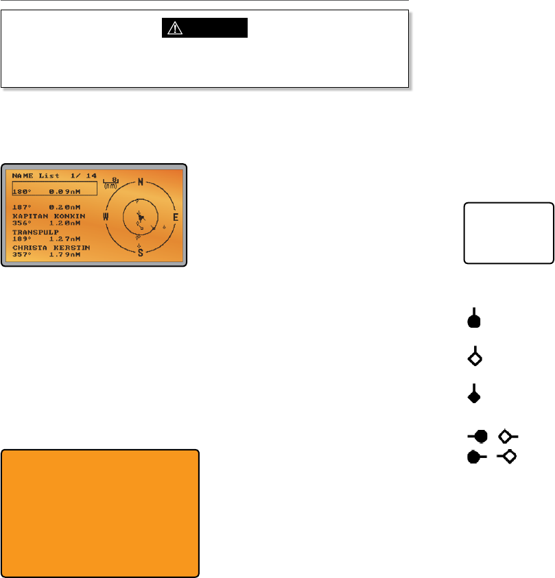
10-4 AIS Information and display
CAUTION
Not all vessels transmit AIS information and therefore not all vessels will be displayed
or listed in the following AIS screens.
AIS vessel information can be displayed on the radios LCD screen:
1. Press the AIS/IC button to display the AIS plotter screen
Note: You must have LAT/LON position information for targets to be displayed on the
plotter PPI.
2. AIS target details will be displayed on the left of the screen. Either the vessels name or
MMSI will be displayed (if the information is available) depending on the setting you
selected in Section "6-2 AIS data display format (AIS DISPLAY)". Also the targets bearing
and distance to you are displayed.
Note: it could take some time before AIS targets are displayed.
3. A simple plotter PPI on the right hand side of the LCD shows the geographical location
of the AIS targets with respect to your position which is in the center of the plotter PPI.
4. Press the Zoom In (3CH +/-) or Zoom Out (Scan) keys to change the scale of the plotter.
The scale available is 1nm / 2 nm / 4 nm / 8 nm / 16 nm / 32 nm.
5. Press the AIS/IC key again to change the display to T/CPA Approach screen.
6. Rotate the knob to highlight any AIS target shown on the plotter screen. The selected
target will have the target symbol filled in.
NAME:OCEANIC.DISCOVERER
MMSI:503492000 IMO: 9292747
CALL SIGN:VMQ8808
DIST: 1.62nM BEAR: 285°
TCPA: ----- HEADING: 195.0°
CPA: 1.62nM ROT: 0.0 /min
WIDTH: 0.0m SOG: 9.9KTS
LENGTH: 60.0m COG: 219.0°
RECEIVED: 1M19S LAT: 36°45.785’S
DRAUGHT:----- LON:174°49.157’E
TYPE: PASSENGER SHIP - ALL SHIPS
OF THIS TYPE
STATUS:UNDERWAY USING ENGINE
7. Press ENT to view full details of the highlighted target such as MMSI, Vessel name,
distance, bearing, heading, ROT, COG, SOG, status and other vessel information.
10-4-1 T/CPA approach screen
1. When in AIS mode, press the AIS/IC key again to toggle between the standard AIS
screen and the T/CPA Approach screen.
2. In TCPA Approach mode, the approaching AIS target's details are listed on the left side
along with it's geographical position on the plotter PPI.
3. The zoom range is automatically selected to the best range according to the selected
target on the left. You can’t change the zoom range in this mode.
4. Press +/- button or rotate the CH knob to select the target, press ENT key to display
target information, or press EXIT key to return to the previous display.
Note: If the radio detects a TCPA or CPA breach, the T/CPA Approach screen will
automatically popup with an alert tone. Press EXIT to stop the alert. The alert will sound again
after 1 minute if the AIS alarm has not been released.
T/CPA APPROACH
228278700
0.59Min 1.0nM
10-4-2 Plotter symbols and meanings
Your vessel is always in the center of the plotter screen. You are represented by a
solid circle, along with a small line that indicates your bearing with respect to North.
All other vessels or targets displayed on the plotter screen are represented by a
diamond shape. These are targets around your vessel that are within the current
zoom distance setting. The small line indicates the targets bearing.
When a target is selected, it is represented by a solid diamond.
Examples:
You and the target vessel are heading away from each other.
You and the target vessel are heading towards each other.
Note: Nautical Miles is the only unit used in AIS mode.
Simrad - RS35 Operation InstructionsSimrad - RS35 Operation Instructions 6564
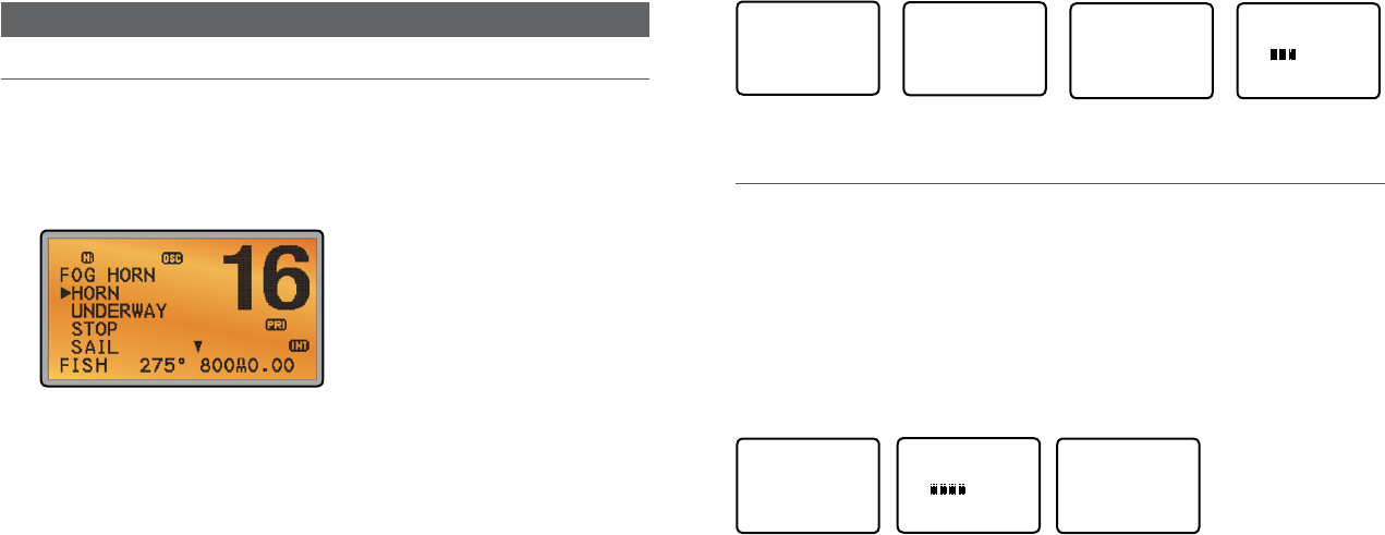
Section 11 - General functionality
11-1 Using the Fog Horn
An appropriate PA speaker must be connected to the Hailer wiring before the FOG HORN
function can be used. The FOG HORN will sound certain international standard fog horn
tones through the hailer speaker depending on the mode selected.
1. Press and hold the AIS/IC button for about 1 second to enter HAILER mode. Select FOG
HORN and press ENT.
2. There are 8 choices of internationally recognized fog horn sounds and timing:
• HORN (Horn) Manual operation
• UNDERWAY (Underway) One long tone
• STOP (Stop) Two long tone
• SAIL (Sail) One long, two short
• ANCHOR (Anchor) One long warble
• TOW ( Tow) One long, three short
• AGROUND (Aground) Warble sequence
• SIREN (Siren) Manual operation
3. Scroll through the menu to select a fog horn type, then press ENT to start the selected
fog horn sounding. All except HORN and SIREN will sound automatically.
4. The fog horn will sound automatically approximately every two minutes until you press
EXIT to cancel it. When the fog horn is not sounding, it is in LISTEN mode.
5. To change the volume, turn the Channel Select knob, or press + or – when the fog horn
is sounding.
6. To operate HORN or SIREN, once selected, press and hold ENT button. This will sound
as long as the ENT button is pressed. You can then also operate PTT to talk through the
Hailer.
HAILER
PA
►FOG HORN
INTERCOM
FOG HORN
►HORN
UNDERWAY
STOP
SAIL ▼
FOG HORN
UNDERWAY ▲
STOP
►SAIL
ANCHOR ▼
SAIL
OUTPUT
VOL
LO HI
Note: you cannot change the volume of the HORN or SIREN.
11-2 Using the PA (Public Address) Hailer
An appropriate Hailer speaker must be connected to the Hailer wiring before the PA function
can be used. The PA allows you to make an announcement at high volume to people or
vessels using the RS35 hand mic. The PA function also features a listen-back mode where the
speaker is used as a microphone to listen for a response.
1. Press and hold the AIS/IC button for about 1 second to enter HAILER mode. Select PA
and press ENT.
2. Press PTT to talk through the hailer. Turn the Channel Select knob, or press + or – to
change the volume. Volume can only be changed while the PTT is pressed.
3. Release PTT to LISTEN for a response.
HAILER
►PA
FOG HORN
INTERCOM
PA
OUTPUT
VOL
LO HI
PA
LISTEN
4. Press EXIT to return to operational mode.
Simrad - RS35 Operation InstructionsSimrad - RS35 Operation Instructions 6766

Section 12 - Wireless Handset functionality
This radio can operate with up to two optional HS35 wireless handsets. When an HS35
wireless handset is successfully 'subscribed' to the radio, the button and screens on each
device will be mimicked.
Note: The HS35 must be subscribed to the RS35 base-station radio before it can be used. See
Section 7 on how to subscribe the wireless handset to the RS35.
Note: Maximum of two handsets can be subscribed to the RS35.
12-1 Using the Wireless Handset
Once the HS35 handset has been paired (subscribed) to the RS35, the screen and button
functionality are mimicked on each device.
Most functions that are provided for on the RS35 can be accessed by the HS35 with the
following differences:
• AIS: There is no AIS PPI on the HS35 screen
• SETUP: Some setup functions are not available on the HS35
When the HS35 is not in use, it should be placed back into the charger cradle. The HS35 is
charged when placed in the cradle via a contact-less inductive charging system.
12-2 Using the Intercom / Conference facility
The Intercom mode works ONLY when one or two optional HS35 handset(s) are installed.
Conference mode is only available when 2 handsets are connected and is used to connect all
3 units together. This disables the radio receiver except for incoming DSC calls.
1. Hold down AIS/IC key to enter INTERCOM or CONFERENCE mode.
HAILER
PA
FOG HORN
►INTERCOM
INTERCOM
PUSH TO TALK
2. The intercom calls the other unit.
3. Press PTT when invited.
4. Press ESC to exit the INTERCOM mode
Simrad - RS35 Operation InstructionsSimrad - RS35 Operation Instructions 6968

Appendix A - Technical specications
Simrad RS35
GENERAL Unit LIMIT
Standard Operation Temperature °C -20ºC to +55ºC (-4ºF to 131ºF)
Normal Working Voltage V 12 V DC battery system (negative ground)
Low battery detect Voltage V 10.5
Rx Current Drain at : Max Audio Power A ≤1.5
: Stand-By A ≤0.25
: Hailer Power A ≤3.5
Tx Current Drain at : Hi Power A ≤6 (@13.6 V DC)
: Lo Power A ≤1.5 (@13.6 V DC)
Dimensions mm 180.5 x 96.3 x 171
Weight kg 1.63
VHF Frequency Range: Transmit MHz 156.025 To 157.425 (default)
VHF Frequency Range: Receive MHz 156.025 To 163.275 (default)
Oscillate Mode PLL
Modulation FM (16KOG3E) DSC (16K0G2B)
Usable channels International, USA, Canada, Weather
(country specific)
Channel Spacing KHz 25
Frequency Stability PPM ±5
Audio power of speaker in mike dBA 80 dBA @ 1m
Audio power of speaker in base dBA 94 dBA @ 1m (Ø=57mm)
Digital Selectivity Calling (DSC) Class-D (EN301025) with dual receiver (individual
CH70)
Standards – DSC ITU-R M.493-13 (US models),
EN 300-338-3 (EU models)
Standards – AIS ITU-R M.1371-4
Standards - Other EN 60950-1:2006 /A1:2010
LCD display 128 x 256 pixel LCD FSTN – 1.3” x 2.6”
Contrast control Yes
Dimming control Yes
Antenna connector SO-239 (50 ohm)
NMEA 2000 connector Micro-C (5 pin)
Waterproof JIS-7
Compass safe distance: 0.5 m (1.5’)
RECEIVER: Unit LIMIT
Intermediate Frequency : 1st MHz 21.4
: 2nd KHz 450
Sensitivity : 12dB SINAD dBuV ≤-6
Squelch Sensitivity : at tight dBuV ≤6
Spurious Response Rejection Ratio dB ≥70
Adjacent Channel Selectivity dB ≥70
Intermodulation Response dB ≥68
S/N at 3KHz Dev. dB ≥40
Audio Output Power At THD 10% W 5W (external speaker output)
Audio Distortion % ≤5
Audio Response dB +1 to -3 dB of 6 dB/octave from 300 Hz to 3 kHZ
TRANSMITTER:
Frequency error PPM ±5
RF Power W Hi: 23 ± 2 / Lo: 0.8 ± 0.2
Maximum Deviation KHz ± 5
S/N at 3KHz Dev. dB 40
Modulation Distortion ±3KHz % ≤5
Audio Response at 1KHz Dev. dB +1 to -3 dB of 6 dB/octave from 300 Hz to 3 kHZ
Spurious/Harmonic Emissions : Hi/LO uW <0.25
Modulation Sensitivity mV ≤20
Transmitter Protection Open/short circuit of antenna
COMMUNICATIONS:
Comm. port - NMEA 0183 NMEA 0183, 4800 baud
Comm. port - NMEA 2000 NMEA 2000
NMEA 0183 input (receive): RMC, GGA, GLL, GNS
NMEA 0183 output (transmit): DSC (for DSC call), DSE (for enhanced position).
AIVDM (AIS)
HAILER:
Audio Power Out W 30W @ 4 Ohms
AIS:
AIS function Yes, dual receivers only
Receiver Frequency MHz 161.975, 162.025
CH87 - 161.975; CH88 - 162.025 (default channel)
Supported AIS Information: –Status/Destination/ETA
–Vessel Name –Type of vessel
–Call sign –MMSI number
–IMO number –Draft/Size of vessel
–Vessel position –SOG/COG/Rate of turn/Heading
Simrad - RS35 Operation InstructionsSimrad - RS35 Operation Instructions 7170

RS35 NMEA 2000 PGNS
127250 Vessel Heading
127258 Magnetic Variation
129025 Position, Rapid Update
129026 COG & SOG, Rapid Update
129029 GNSS Position Data
129033 Time & Date
129038 Class A position report (Rx,Tx)
129039 Class B position report (Rx,Tx)
129040 Class B extended position report (Rx, Tx)
129041 AIS Aids to Navigation (AtoN) Report
129283 Cross Track Error
129284 Navigation Data
129285 Navigation Route/WP Information
129792 DGNSS Broadcast binary message (Tx)
129793 UTC and date report (Tx)
129794 Class A static and voyage related data (rx, tx)
129795 Addressed binary message (tx)
129796 Acknowledge (tx)
129797 Binary broadcast message (tx)
129798 SAR Aircraft Position report (tx)
129799 Radio Frequency/Mode/Power
129800 UTC/Date enquiry (tx)
129801 Addressed safety msg (rx,tx)
129802 Broadcast safety msg (rx,tx)
129803 Interrogation (tx)
129804 Assignment Mode Command (tx)
129805 Data Link Management message (tx)
129807 AIS Group Assignment
129808 DSC Call Information
129809 AIS Class B “CS” Static Data Report, Part A
129810 AIS Class B “CS” Static Data Report, Part B
130074 Route and WP Service - WP List - WP Name & Position
130842 AIS and VHF Messages (Simrad Proprietary for AIS Class B ‘CS’)
Wireless Handset: Unit LIMIT
Rx Frequency MHz 2401~2480
Rx Channel Number 80
Rx Sensitivity @ PER <=1% dBm -92
Rx Current mA <60
Nominal Transmit Power/Peak Power dBm 18+/-2
Tx Frequency Error ppm <+/-30
Tx Current mA <150
Functional range mtrs
HS35 cradle voltage V 12 V DC battery system (negative ground)
HS35 cradle current drain A ≤0.5
Specications are subject to change without notice.
Simrad - RS35 Operation InstructionsSimrad - RS35 Operation Instructions 7372

Appendix B - Troubleshooting
1. The transceiver will not power up.
A fuse may have blown or there is no voltage getting to the transceiver.
a) Check the power cable for cuts, breaks, or squashed sections.
b) After checking the wiring, replace the 7 Amp fuse.
c) Check the battery voltage. This must be greater than 10.5V.
2. The transceiver blows the fuse when the power is switched on.
The power wires may have been reversed.
a) Check that the red wire is connected to the positive battery terminal, and the black wire
is connected to the negative battery terminal.
3. The speaker makes popping or whining noises when the engine is running.
Electrical noise may be interfering with the transceiver.
a) Re-route the power cables away from the engine.
b) Add a noise suppressor to the power cable.
c) Use resistive spark plug wires and/or use an alternator whine filter.
4. No sound from the external speaker.
a) Check that the external speaker cable is physically connected.
b) Check the soldering of the external speaker cable.
5. Transmissions are always on low power, even when high (Hi) power is selected.
The antenna may be faulty.
a) Test the transceiver with a different antenna.
b) Have the antenna checked out.
6. Battery symbol is displayed.
The power supply is too low.
a) Check the battery voltage. This should be at least 10.5 V ± 0.5 V DC.
b) Check the alternator on the vessel.
7. GPS alarm sounds and LCD shows: Please check GPS link! The NO GPS symbol is
shown.
GPS data has been lost. This sequence will repeat every 4 hours until GPS data from an opera-
tional GPS receiver is available. The GPS cable may faulty or the GPS setting may be incorrect:
a) Manually enter your position and UTC time data (see Section 3.6.1)
b) Check that the GPS cable is physically connected.
c) Check the polarity of the GPS cable.
d) Check the baud rate setting of the GPS if applicable. The baud rate setting should be
4800. Parity should be set to NONE.
Appendix C - US & ROW VHF marine channel charts
The following channel charts are provided for reference only and may not be correct for all regions.
It is the operators responsibility to ensure correct channels and frequencies are used for local
regulations.
C-1 International channel chart
CH TX (MHz) RX (MHz) MODE TRAFFIC TYPE SHIP TO
SHIP
SHIP TO
SHORE
NAME TAG REMARK
01 156.050 160.650 D Public Correspondence No Yes TELEPHONE
02 156.100 160.700 D Public Correspondence No Yes TELEPHONE
03 156.150 160.750 D Public Correspondence No Yes TELEPHONE
04 156.200 160.800 D Port Operations No Yes PORT OPS
05 156.250 160.850 D Port Operations No Yes PORT OPS/VTS
06 156.300 156.300 S Inter-ship Safety Yes No SAFETY
07 156.350 160.950 D Port Operations No Yes PORT OPS
08 156.400 156.400 S Commercial (inter-ship only) Yes No COMMERCIAL
09 156.450 156.450 S Inter-ship Yes Yes CALLING
10 156.500 156.500 S Commercial Yes Yes COMMERCIAL
11 156.550 156.550 S Port Operations Yes Yes VTS
12 156.600 156.600 S Port Operations Yes Yes PORT OPS/VTS
13 156.650 156.650 S Inter-ship Navigation Safety
(bridge-to bridge) Yes No BRIDGE COM
14 156.700 156.700 S Port Operations Yes Yes PORT OPS/VTS
15 156.750 156.750 S Port Operations Yes Yes PORT OPS 1 1W only
16 156.800 156.800 S International Distress, Safety,
and Calling Yes Yes DISTRESS
17 156.850 156.850 S State Controlled Yes Yes SAR 1 1W only
18 156.900 161.500 D Port Operations No Yes PORT OPS
19 156.950 161.550 D Ship to Shore No Yes SHIP-SHORE
20 157.000 161.600 D Port Operations No Yes PORT OPS
21 157.050 161.650 D Port Operations No Yes PORT OPS
22 157.100 161.700 D Port Operations No Yes PORT OPS
23 157.150 161.750 D Public Correspondence No Yes TELEPHONE
24 157.200 161.800 D Public Correspondence No Yes TELEPHONE
25 157.250 161.850 D Public Correspondence No Yes TELEPHONE
26 157.300 161.900 D Public Correspondence No Yes TELEPHONE
27 157.350 161.950 D Public Correspondence No Yes TELEPHONE
28 157.400 162.000 D Public Correspondence No Yes TELEPHONE
60 156.025 160.625 D Public Correspondence No Yes TELEPHONE
61 156.075 160.675 D Port Operations No Yes PORT OPS
Simrad - RS35 Operation InstructionsSimrad - RS35 Operation Instructions 7574
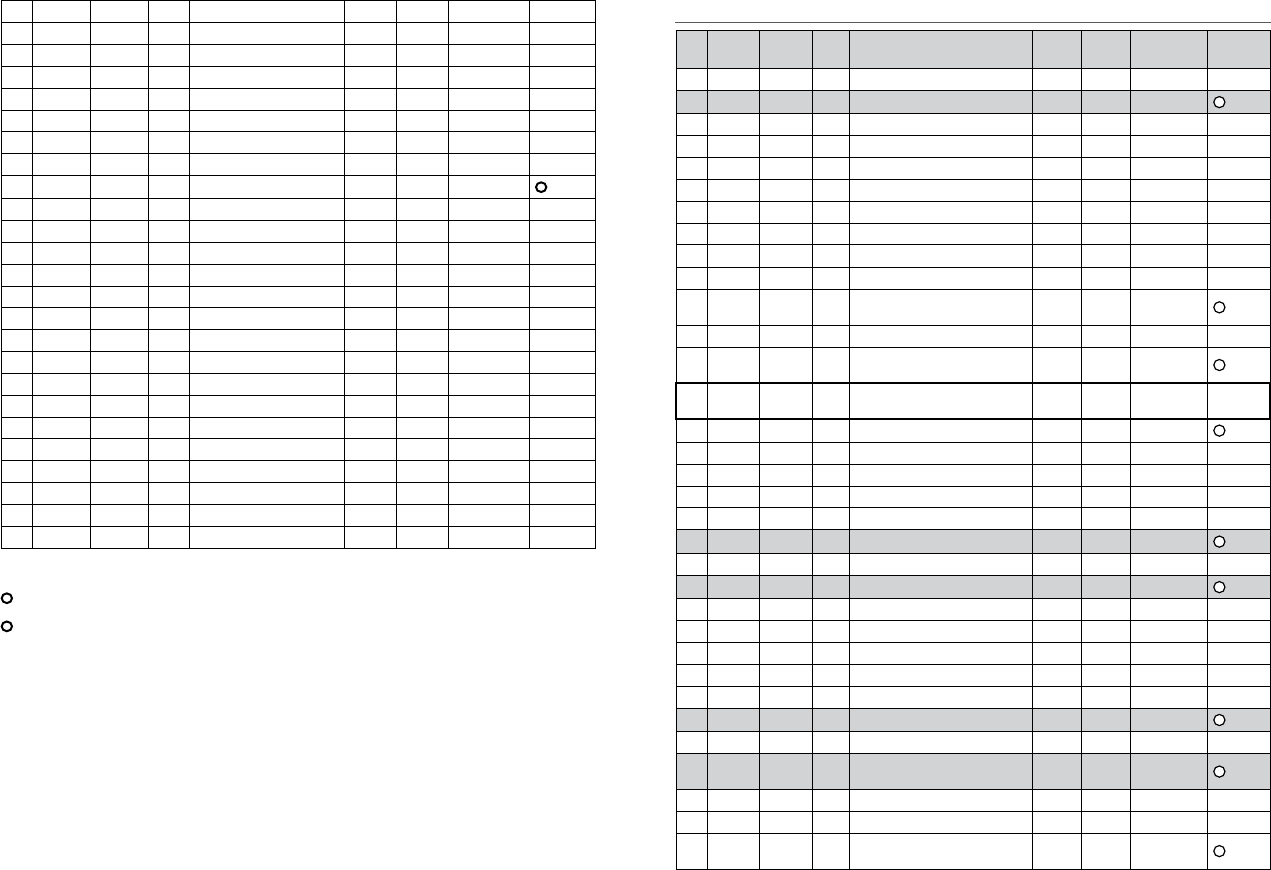
62 156.125 160.725 D Port Operations No Yes PORT OPS
63 156.175 160.775 D Port Operations No Yes PORT OPS
64 156.225 160.825 D Public Correspondence No Yes TELEPHONE
65 156.275 160.875 D Port Operations No Yes PORT OPS
66 156.325 160.925 D Port Operations No Yes PORT OPS
67 156.375 156.375 S Commercial, bridge-to-bridge Yes No BRIDGE COM
68 156.425 156.425 S Inter-ship Yes No SHIP-SHIP
69 156.475 156.475 S Port Operations Yes Yes PORT OPS
70 156.525 156.525 - Digital Selective Calling - DSC ------ ------ DSC 2
71 156.575 156.575 S Port Operations Yes Yes PORT OPS
72 156.625 156.625 S Inter-ship Yes No SHIP-SHIP
73 156.675 156.675 S Port Operations Yes Yes PORT OPS
74 156.725 156.725 S Port Operations Yes Yes PORT OPS
77 156.875 156.875 S Ship to Shore Yes No SHIP-SHORE
78 156.925 161.525 D Ship to Shore No Yes SHIP-SHORE
79 156.975 161.575 D Port Operations No Yes PORT OPS
80 157.025 161.625 D Port Operations No Yes PORT OPS
81 157.075 161.675 D Public Correspondence No Yes TELEPHONE
82 157.125 161.725 D Public Correspondence No Yes TELEPHONE
83 157.175 161.775 D Public Correspondence No Yes TELEPHONE
84 157.225 161.825 D Public Correspondence No Yes TELEPHONE
85 157.275 161.875 D Public Correspondence No Yes TELEPHONE
86 157.325 161.925 D Public Correspondence No Yes TELEPHONE
87 157.375 161.975 D Public Correspondence No Yes TELEPHONE
88 157.425 162.025 D Public Correspondence No Yes TELEPHONE
Special notes on international channel usage
1. LOW POWER (1W) only.
2. Channel 70 is designated for use exclusively for Digital Selective Calling (DSC), such as Distress,
Safety, and Ship Calls. No voice communication is allowed on CH70.
This channel is only available on DSC enabled radios.
Note:
• The INTERNATIONAL channel bank is not legal for use in U.S. or Canada waters.
• Select the INTERNATIONAL channel bank for use in Australia, New Zealand and other Asia Pacific
regions, and all other regions where otherwise not specified.
KEY: S = Simplex operating channel; D = Duplex operating channel.
C-2 USA channel chart
CH TX (MHz) RX (MHz) MODE TRAFFIC TYPE SHIP TO
SHIP
SHIP TO
SHORE
NAME TAG REMARK
01A 156.050 156.050 S Port Operations, Selected VTS Areas Yes Yes PORT OPS/VTS
03A 156.150 156.150 S US Government, Coast Guard Yes Yes UNAUTHORIZED 4
05A 156.250 156.250 S Port Operations, Selected VTS Areas Yes Yes PORT OPS/VTS
06 156.300 156.300 S Inter-ship Safety Yes No SAFETY
07A 156.350 156.350 S Commercial Yes Yes COMMERCIAL
08 156.400 156.400 S Commercial (inter-ship only) Yes No COMMERCIAL
09 156.450 156.450 S Recreational Calling Channel Yes Yes CALLING
10 156.500 156.500 S Commercial Yes Yes COMMERCIAL
11 156.550 156.550 S Commercial, VTS in Selected Areas Yes Yes VTS
12 156.600 156.600 S Port Operations, Selected VTS Areas Yes Yes PORT OPS/VTS
13 156.650 156.650 S Inter-ship Navigation Safety (bridge-to
bridge), 1W with Power-up Yes No BRIDGE COM 3 1W
14 156.700 156.700 S Port Operations, Selected VTS Areas Yes Yes PORT OPS/VTS
15 --- 156.750 S Environmental ------ ------ ENVIRONMEN-
TAL 2 RX only
16 156.800 156.800 S International Distress, Safety, and
Calling Yes Yes DISTRESS
17 156.850 156.850 S State Controlled Yes Yes SAR 1 1W only
18A 156.900 156.900 S Commercial Yes Yes COMMERCIAL
19A 156.950 156.950 S Commercial Yes Yes COMMERCIAL
20 157.000 161.600 D Port Operations, Canadian Coast Guard No Yes PORT OPS
20A 157.000 157.000 S Port Operations Yes Yes PORT OPS
21A 157.050 157.050 S U.S. Government, Canadian Coast Guard Yes Yes UNAUTHORIZED 4
22A 157.100 157.100 S Coast Guard Liaison Yes Yes COAST GUARD
23A 157.150 157.150 S U.S. Government, Coast Guard Yes Yes UNAUTHORIZED 4
24 157.200 161.800 D Public Correspondence, Marine operator No Yes TELEPHONE
25 157.250 161.850 D Public Correspondence, Marine operator No Yes TELEPHONE
26 157.300 161.900 D Public Correspondence, Marine operator No Yes TELEPHONE
27 157.350 161.950 D Public Correspondence, Marine operator No Yes TELEPHONE
28 157.400 162.000 D Public Correspondence, Marine operator No Yes TELEPHONE
61A 156.075 156.075 S U.S. Government, Canadian Coast Guard Yes Yes UNAUTHORIZED 4
63A 156.175 156.175 S Port Operations, VTS in Selected Areas Yes Yes PORT OPS/VTS
64A 156.225 156.225 S U.S. Government, Canadian Commercial
Fishing Yes Yes UNAUTHORIZED 4
65A 156.275 156.275 S Port Operations Yes Yes PORT OPS
66A 156.325 156.325 S Port Operations Yes Yes PORT OPS
67 156.375 156.375 S Commercial, bridge-to-bridge, 1W with
Power-up Yes No BRIDGE COM 3 1W
Simrad - RS35 Operation InstructionsSimrad - RS35 Operation Instructions 7776
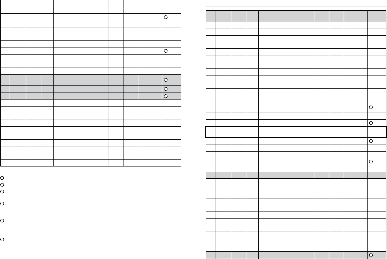
68 156.425 156.425 S Boat Operations, Recreational Yes No SHIP - SHIP
69 156.475 156.475 S Boat Operations, Recreational Yes Yes PLEASURE
70 156.525 156.525 Digital Selective Calling - DSC ------ ------ DSC 6
71 156.575 156.575 S Boat Operations, Recreational Yes Yes PLEASURE
72 156.625 156.625 S Boat Operations, Recreational Yes No SHIP - SHIP
73 156.675 156.675 S Port Operations Yes Yes PORT OPS
74 156.725 156.725 S Port Operations Yes Yes PORT OPS
77 156.875 156.875 S Port Operations Yes Yes PORT OPS 1 1W only
78A 156.925 156.925 S Boat Operations, Recreational Yes No SHIP - SHIP
79A 156.975 156.975 S Commercial Yes Yes COMMERCIAL
80A 157.025 157.025 S Commercial Yes Yes COMMERCIAL
81A 157.075 157.075 S U.S. Government, Environmental Protec-
tion Agency Operations Yes Yes UNAUTHORIZED 4
82A 157.125 157.125 S U.S. Government, Canadian Coast Guard Yes Yes UNAUTHORIZED 4
83A 157.175 157.175 S U.S. Government, Canadian Coast Guard Yes Yes UNAUTHORIZED 4
84 157.225 161.825 D Public Correspondence, Marine Operator No Yes TELEPHONE
84A 157.225 157.225 S Public Correspondence, Marine Operator
85 157.275 161.875 D Public Correspondence, Marine Operator No Yes TELEPHONE
85A 157.275 157.275 S Public Correspondence, Marine Operator
86 157.325 161.925 D Public Correspondence, Marine Operator No Yes TELEPHONE
86A 157.325 157.325 S Public Correspondence, Marine Operator
87 157.375 161.975 D Public Correspondence, Marine Operator No Yes TELEPHONE
87A 157.375 157.375 S Public Correspondence, Marine Operator
88 157.425 162.025 D Public Correspondence, Marine Operator No Yes TELEPHONE
88A 157.425 157.425 S Commercial, Inter-ship Only Yes No COMMERCIAL
Special notes on USA channel usage
1. LOW POWER (1 W) only.
2. Receive Only.
3. LOW POWER (1 W) initially. Override to HIGH POWER by holding down H/L key before transmitting.
Used normally in bridge-to-bridge communications.
4. Lightly shaded simplex channels 03A, 21A, 23A, 61A, 64A, 81A, 82A, and 83A cannot be lawfully used
in U.S. waters unless special authorization is obtained from the U.S. Coast Guard.
Not for use by the general public.
5. The letter “A” illuminated by the channel number indicates the USA channel is simplex.
This same channel is always duplex when selecting International. There is no “A” reference for Interna-
tional channels. The letter “B” is only used for some Canadian “Receive only” channels.
6. Channel 70 is designated for use exclusively for Digital Selective Calling (DSC), such as Distress,
Safety, and Ship Calls. No voice communication is allowed on CH70.
This channel is only available on DSC enabled radios.
KEY: S = Simplex operating channel; D = Duplex operating channel.
C-3 CANADA channel chart
CH TX (MHz) RX (MHz) MODE TRAFFIC TYPE SHIP TO
SHIP
SHIP TO
SHORE
NAME TAG REMARK
01 156.050 160.650 D Public Correspondence No Yes TELEPHONE
02 156.100 160.700 D Public Correspondence No Yes TELEPHONE
03 156.150 160.750 D Public Correspondence No Yes TELEPHONE
04A 156.200 156.200 S Canadian Coast Guard, SAR Yes Yes CANADIAN CG
05A 156.250 156.250 S Port Operations, VTS in Selected Areas Yes Yes PORT OPS/VTS
06 156.300 156.300 S Inter-ship Safety Yes No SAFETY
07A 156.350 156.350 S Commercial Yes Yes COMMERCIAL
08 156.400 156.400 S Commercial (inter-ship only) Yes No COMMERCIAL
09 156.450 156.450 S Recreational Calling Channel Yes Yes CALLING
10 156.500 156.500 S Commercial Yes Yes COMMERCIAL
11 156.550 156.550 S Commercial, VTS in Selected Areas Yes Yes VTS
12 156.600 156.600 S Port Operations, VTS in Selected Areas Yes Yes PORT OPS/VTS
13 156.650 156.650 S Inter-ship Navigation Safety (bridge-to
bridge) 1W with power-up Yes No BRIDGE COM 3 1W
14 156.700 156.700 S Port Operations, VTS in Selected Areas Yes Yes PORT OPS/VTS
15 156.750 156.750 S Commercial Yes Yes COMMERCIAL 1 1W only
16 156.800 156.800 S International Distress, Safety, and
Calling Yes Yes DISTRESS
17 156.850 156.850 S State Controlled Yes Yes SAR 1 1W only
18A 156.900 156.900 S Commercial Yes Yes COMMERCIAL
19A 156.950 156.950 S Canadian Coast Guard Yes Yes CANADIAN CG
20 157.000 161.600 D Canadian Coast Guard No Yes CANADIAN CG 1 1W only
21 157.050 161.650 D Port Operations No Yes PORT OPS
21A 157.050 157.050 S U.S. Government, Canadian Coast Guard Yes Yes UNAUTHORIZED
21B --- 161.650 S Port Operations ------ ------ PORT OPS RX only
22A 157.100 157.100 S Canadian Coast Guard Liaison Yes Yes CANADIAN CG
23 157.150 161.750 D Public Correspondence No Yes TELEPHONE
24 157.200 161.800 D Public Correspondence No Yes TELEPHONE
25 157.250 161.850 D Public Correspondence No Yes TELEPHONE
25B --- 161.850 S Public Correspondence ------ ------ TELEPHONE RX only
26 157.300 161.900 D Public Correspondence No Yes TELEPHONE
27 157.350 161.950 D Public Correspondence No Yes TELEPHONE
28 157.400 162.000 D Public Correspondence No Yes TELEPHONE
28B --- 162.000 S Public Correspondence ------ ------ TELEPHONE RX only
60 156.025 160.625 D Public Correspondence No Yes TELEPHONE
61A 156.075 156.075 S U.S. Government, Canadian Coast Guard Yes Yes UNAUTHORIZED 4
Simrad - RS35 Operation InstructionsSimrad - RS35 Operation Instructions 7978
62A 156.125 156.125 S Canadian Coast Guard Yes Yes CANADIAN CG
64 156.225 160.825 D Public Correspondence, Duplex No Yes TELEPHONE
64A 156.225 156.225 S U.S. Government, Canadian Commercial
Fishing Yes Yes UNAUTHORIZED 4
65A 156.275 156.275 S Port Operations Yes Yes PORT OPS
66A 156.325 156.325 S Port Operations Yes Yes PORT OPS 1 1W only
67 156.375 156.375 S Commercial, SAR Yes No COMMERCIAL
68 156.425 156.425 S Boat Operations, Recreational Yes No SHIP - SHIP
69 156.475 156.475 S Commercial Fishing Only Yes Yes COMMERCIAL
70 156.525 156.525 S Digital Selective Calling - DSC ------ ------ DSC 6
71 156.575 156.575 S Boat Operations, Recreational Yes Yes PLEASURE
72 156.625 156.625 S Inter-ship Yes No SHIP - SHIP
73 156.675 156.675 S Commercial Fishing Only Yes Yes COMMERCIAL
74 156.725 156.725 S Commercial Fishing Only Yes Yes COMMERCIAL
77 156.875 156.875 S Port Operations Yes Yes PORT OPS 1 1W only
78A 156.925 156.925 S Boat Operations, Recreational Yes No SHIP - SHIP
79A 156.975 156.975 S Commercial Yes Yes COMMERCIAL
80A 157.025 157.025 S Commercial Yes Yes COMMERCIAL
81A 157.075 157.075 S U.S. Government Operations Yes Yes UNAUTHORIZED 4
82A 157.125 157.125 S U.S. Government, Canadian Coast Guard Yes Yes UNAUTHORIZED 4
83 157.175 161.775 D Canadian Coast Guard Yes Yes CANADIAN CG
83A 157.175 157.175 S U.S. Government, Canadian Coast Guard Yes Yes UNAUTHORIZED 4
83B --- 161.775 S Canadian Coast Guard, RX Only ------ ------ CANADIAN CG
84 157.225 161.825 D Public Correspondence, Marine Operator No Yes TELEPHONE
85 157.275 161.875 D Public Correspondence, Marine Operator No Yes TELEPHONE
86 157.325 161.925 D Public Correspondence, Marine Operator No Yes TELEPHONE
87 157.375 161.975 D Public Correspondence, Marine Operator No Yes TELEPHONE
88 157.425 162.025 D Public Correspondence, Marine Operator No Yes TELEPHONE
Special notes on Canada channel usage
1. LOW POWER (1 W) only.
2. Receive Only.
3. LOW POWER (1 W) initially. Override to HIGH POWER by holding down H/L key before transmitting.
Used normally in bridge-to-bridge communications.
4. Lightly shaded simplex channels 21A, 23A, 61A, 64A, 81A, 82A, and 83A cannot be lawfully used in
Canada waters unless special authorization is obtained from the Canadian Coast Guard.
Not for use by the general public.
5. The letter “A” illuminated by the channel number indicates the Canada channel is simplex. This same
channel is always duplex when selecting International.
There is no “A” reference for International channels. The letter “B” is only used for some Canadian
“Receive only” channels.
6. Channel 70 is designated for use exclusively for Digital Selective Calling (DSC), such as Distress,
Safety, and Ship Calls. No voice communication is allowed on CH70.
This channel is only available on DSC enabled radios.
Note: The CANADA mode is not legal to use in U.S. waters.
KEY: S = Simplex operating channel; D = Duplex operating channel.
C-4 US & Canada WEATHER channels
CH RX (MHz) TRAFFIC TYPE NAME REMARK
WX01 162.550 NOAA Weather Channel NOAA WX RX only
WX02 162.400 NOAA Weather Channel NOAA WX RX only
WX03 162.475 NOAA Weather Channel NOAA WX RX only
WX04 162.425 NOAA Weather Channel NOAA WX RX only
WX05 162.450 NOAA Weather Channel NOAA WX RX only
WX06 162.500 NOAA Weather Channel NOAA WX RX only
WX07 162.525 NOAA Weather Channel NOAA WX RX only
WX08 161.650 CANADIAN Weather Channel CANADA WX RX only
WX09 161.775 CANADIAN Weather Channel CANADA WX RX only
WX10 163.275 NOAA Weather Channel NOAA WX RX only
Simrad - RS35 Operation InstructionsSimrad - RS35 Operation Instructions 8180

C-5 EAS (Emergency Alert Systems) alerts
National Codes
Nature of Activation
Event Codes Message
Emergency Action Notification (National only) EAN WARNING
EAT ADVISORY
National Information Center NIC ADVISORY
National Periodic Test NPT TEST
Required Monthly Test RMT TEST
Required Weekly Test RWT TEST
State and Local Codes
Nature of Activation
Event Codes Message
Avalanche Warning AVW WARNING
Avalanche Watch AVA WATCH
Blizzard Warning BZW WARNING
Child Abduction Emergency CAE WARNING
Civil Danger Warning CDW WARNING
Civil Emergency Message CEM WARNING
Coastal Flood Warning CFW WARNING
Coastal Flood Watch CFA WATCH
Dust Storm Warning DSW WARNING
Earthquake Warning EQW WARNING
Evacuation Immediate EVI WARNING
Fire Warning FRW WARNING
Flash Flood Warning FFW WARNING
Flash Flood Watch FFA WATCH
Flash Flood Statement FFS ADVISORY
Flood Warning FLW WARNING
Flood Watch FLA WATCH
Flood Statement FLS ADVISORY
Hazardous Materials Warning HMW WARNING
High Wind Warning HWW WARNING
High Wind Watch HWA WATCH
State and Local Codes
Nature of Activation
Event Codes Message
Hurricane Warning HUW WARNING
Hurricane Watch HUA WATCH
Hurricane Statement HLS ADVISORY
Law Enforcement Warning LEW WARNING
Local Area Emergency LAE WARNING
911 Telephone Outage Emergency TOE WARNING
Nuclear Power Plant Warning NUW WARNING
Radiological Hazard Warning RHW WARNING
Severe Thunderstorm Warning SVR WARNING
Severe Thunderstorm Watch SVA WATCH
Severe Weather Statement SVS ADVISORY
Shelter in Place Warning SPW WARNING
Special Marine Warning SMW WARNING
Special Weather Statement SPS ADVISORY
Tornado Warning TOR WARNING
Tornado Watch TOA WATCH
Tropical Storm Warning TRW WARNING
Tropical Storm Watch TRA WATCH
Tsunami Warning TSW WARNING
Tsunami Watch TSA WATCH
Volcano Warning VOW WARNING
Winter Storm Warning WSW WARNING
Winter Storm Watch WSA WATCH
For more information about the Emergency Alert System and event codes, visit:
http://www.nws.noaa.gov/os/eas_codes.shtml
Simrad - RS35 Operation InstructionsSimrad - RS35 Operation Instructions 8382
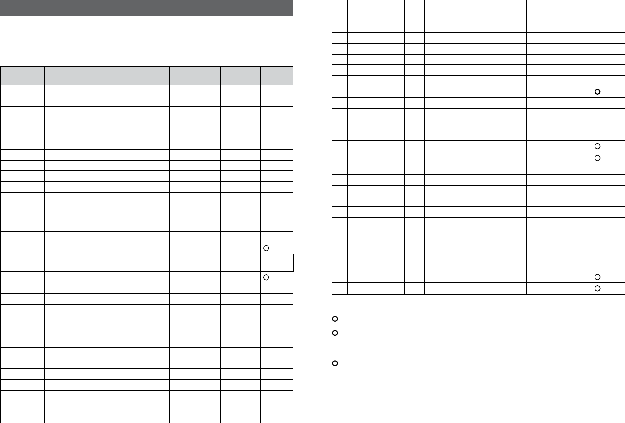
D-1 EU international channel chart
CH TX (MHz) RX (MHz) MODE TRAFFIC TYPE SHIP TO
SHIP
SHIP TO
SHORE
NAME TAG REMARK
01 156.050 160.650 D Public Correspondence, Port Op No Yes PHONE-PORTOP
02 156.100 160.700 D Public Correspondence, Port Op No Yes PHONE-PORTOP
03 156.150 160.750 D Public Correspondence, Port Op No Yes PHONE-PORTOP
04 156.200 160.800 D Public Correspondence, Port Op No Yes PHONE-PORTOP
05 156.250 160.850 D Public Correspondence, Port Op No Yes PHONE-PORTOP
06 156.300 156.300 S Inter-ship Safety Yes No SAFETY
07 156.350 160.950 D Public Correspondence, Port Op No Yes PHONE-PORTOP
08 156.400 156.400 S Commercial (inter-ship only) Yes No SHIP-SHIP
09 156.450 156.450 S Inter-ship Yes Yes SHIP-SHIP
10 156.500 156.500 S Inter-ship Yes Yes SHIP-SHIP
11 156.550 156.550 S Port Operations Yes Yes PORT OPS
12 156.600 156.600 S Port Operations Yes Yes PORT OPS
13 156.650 156.650 S Inter-ship Navigation Safety
(bridge-to bridge) Yes No SAFETY COM
14 156.700 156.700 S Port Operations Yes Yes PORT OPS
15 156.750 156.750 S Inter-ship Yes Yes PORT OPS 1 1W only
16 156.800 156.800 S International Distress, Safety,
and Calling Yes Yes DISTRESS
17 156.850 156.850 S Inter-ship Yes Yes PORT OPS 1 1W only
18 156.900 161.500 D Public Correspondence, Port Op No Yes PHONE-PORTOP
19 156.950 161.550 D Public Correspondence, Port Op No Yes PHONE-PORTOP
20 157.000 161.600 D Public Correspondence, Port Op No Yes PHONE-PORTOP
21 157.050 161.650 D Public Correspondence, Port Op No Yes PHONE-PORTOP
22 157.100 161.700 D Public Correspondence, Port Op No Yes PHONE-PORTOP
23 157.150 161.750 D Public Correspondence, Port Op No Yes PHONE-PORTOP
24 157.200 161.800 D Public Correspondence, Port Op No Yes PHONE-PORTOP
25 157.250 161.850 D Public Correspondence, Port Op No Yes PHONE-PORTOP
26 157.300 161.900 D Public Correspondence, Port Op No Yes PHONE-PORTOP
27 157.350 161.950 D Public Correspondence, Port Op No Yes PHONE-PORTOP
28 157.400 162.000 D Public Correspondence, Port Op No Yes PHONE-PORTOP
60 156.025 160.625 D Public Correspondence, Port Op No Yes PHONE-PORTOP
61 156.075 160.675 D Public Correspondence, Port Op No Yes PHONE-PORTOP
Appendix D - EU VHF marine channel charts
The following channel charts are provided for reference only and may not be correct for all regions.
It is the operators responsibility to ensure correct channels and frequencies are used for local regu-
lations. For specific channel information for your country, please refer to local authorities.
62 156.125 160.725 D Public Correspondence, Port Op No Yes PHONE-PORTOP
63 156.175 160.775 D Public Correspondence, Port Op No Yes PHONE-PORTOP
64 156.225 160.825 D Public Correspondence, Port Op No Yes PHONE-PORTOP
65 156.275 160.875 D Public Correspondence, Port Op No Yes PHONE-PORTOP
66 156.325 160.925 D Public Correspondence, Port Op No Yes PHONE-PORTOP
67 156.375 156.375 S Commercial, bridge-to-bridge Yes No SHIP-SHIP
68 156.425 156.425 S Port Operations Yes No PORT OPS
69 156.475 156.475 S Inter-ship Yes Yes SHIP-SHIP
70 156.525 156.525 - Digital Selective Calling - DSC ------ ------ DSC 2
71 156.575 156.575 S Port Operations Yes Yes PORT OPS
72 156.625 156.625 S Inter-ship Yes No SHIP-SHIP
73 156.675 156.675 S Inter-ship Yes Yes SHIP-SHIP
74 156.725 156.725 S Port Operations Yes Yes PORT OPS
75 156.775 156.775 S Port Operations Yes Yes PORT OPS 1 1W only
76 156.825 156.825 S Port Operations Yes Yes PORT OPS 1 1W only
77 156.875 156.875 S Inter-ship Yes No SHIP-SHIP
78 156.925 161.525 D Public Correspondence, Port Op No Yes PHONE-PORTOP
79 156.975 161.575 D Public Correspondence, Port Op No Yes PHONE-PORTOP
80 157.025 161.625 D Public Correspondence, Port Op No Yes PHONE-PORTOP
81 157.075 161.675 D Public Correspondence, Port Op No Yes PHONE-PORTOP
82 157.125 161.725 D Public Correspondence, Port Op No Yes PHONE-PORTOP
83 157.175 161.775 D Public Correspondence, Port Op No Yes PHONE-PORTOP
84 157.225 161.825 D Public Correspondence, Port Op No Yes PHONE-PORTOP
85 157.275 161.875 D Public Correspondence, Port Op No Yes PHONE-PORTOP
86 157.325 161.925 D Public Correspondence, Port Op No Yes PHONE-PORTOP
87 157.375 157.375 S Port Operations No Yes PORT OPS 3
88 157.425 157.425 S Port Operations No Yes PORT OPS 3
Special notes on EU international channel usage
1. LOW POWER (1W) only.
2. Channel 70 is designated for use exclusively for Digital Selective Calling (DSC), such as Distress,
Safety, and Ship Calls. No voice communication is allowed on CH70.
This channel is only available on DSC enabled radios.
3. Maybe Duplex in some regions
KEY: S = Simplex operating channel; D = Duplex operating channel.
Simrad - RS35 Operation InstructionsSimrad - RS35 Operation Instructions 8584

D-2 Inland waterways country specific table - ATIS ON
For specific channel information for your country, please refer to local authorities.
CH SPECIFIC FOOT-
NOTES
TRANSMITTING
FREQUENCY (MHZ)
SHIP-TO-SHIP SHIP-TO PORT NAUTICAL
INFORMATION
SHIP LAND
60 a) 156.025 160.625 x
01 a) 156.05 160.65 x
61 a) 156.075 160.675 x
02 a) 156.1 160.7 x
62 a) 156.125 160.725 x
03 a) 156.15 160.75 x
63 a) 156.175 160.775 x
04 a) 156.2 160.8 x
64 a) 156.225 160.825 x
05 a) 156.25 160.85 x
65 a) 156.275 160.875 x
06 a) b) 156.3 156.3 x
66 a) 156.325 160.925 x
07 a) 156.35 160.95 x
67 a) c) 156.375 156.375 x
08 a) q) 156.4 156.4 x
68 a) 156.425 156.425 x
09 a) b) c) 156.45 156.45 x
69 a) 156.475 156.475 x
10 e) 156.5 156.5 x
70 a) 156.525 156.525 Digital selective calling for distress, safety and calling
11 156.55 156.55 x
71 156.575 156.575 x
12 156.6 156.6 x
72 a) r) 156.625 156.625 x
13 f) 156.65 156.65 x
73 f) g) 156.675 156.675 x
14 q) 156.7 156.7 x
74 a) 156.725 156.725 x
15 h) 156.75 156.75 x
75 o) 156.775 156.775 x
16 i) 156.8 156.8 x
76 j) d) o) 156.825 156.825 x
17 h) 156.85 156.85 x
General remarks to Country Specic table:
1 The channels for service categories ship-to-ship and nautical information may also
be used for vessel traffic -sys tems by traffic centres.
2 In some countries, frequencies certain channels are used for an other service
category or other radio services. These countries are Austria, Bulgaria, Croatia, the
Federal Republic of Yugosla via, Hun gary, Moldova, Romania, the Russian Federation,
the Slovak Republic, the Czech Republic (with exemption of channels 08, 09, 72,
74 and 86), Ukraine and the Federal Republic of Yugosla via. The Administra tions
concerned should make any possible attempt to make these fre quencies channels
as soon as possible available for the radiotelephone service on Inland Waterways
and/or the required service catego ry.
77 a) k) 156.875 156.875 x
18 156.9 161.5 x
78 156.925 161.525 x
19 156.95 161.55 x
79 a) 156.975 161.575 x
20 157 161.6 x
80 157.025 161.625 x
21 a) 157.05 161.65 x
81 a) 157.075 161.675 x
22 157.1 161.7 x
82 l) m) 157.125 161.725 x
23 m) 157.15 161.75 x
83 a) m) 157.175 161.775 x
24 m) 157.2 161.8 x
84 m) 157.225 161.825 x
25 m) 157.25 161.85 x
85 a) m) 157.275 161.875 x
26 m) 157.3 161.9 x
86 a) m) 157.325 161.925 x
27 m) 157.35 161.95 x
87 a) d) 157.375 157.375 x
28 m) 157.4 162 x
88 a) p) 157.425 157.425 x
AIS 1 a) n) 161.975 161.975
AIS 2 a) n) 162.025 162.025
Simrad - RS35 Operation InstructionsSimrad - RS35 Operation Instructions 8786

Explanation of specic footnotes in Country Specic table:
a. In the countries mentioned under remark 2, it is strictly prohibited to use this channel.
b. This channel is not allowed to be used between Rhine km 150 and km 350.
c. In the Netherlands, this channel is used by for its on-scene communi cations during
safety operati ons on the North Sea, IJsselmeer, Wadden zee, Ooster- and Wester schelde.
d. This channel may also be used for piloting, mooring, tugging and for other nautical
purposes.
e. This channel is the first ship-to-ship channel, unless the competent authority has
designated an other channel. In the countries mentioned under remark 2, it is allowed
that the output power is set to a value between 6 and 25 W until 1 January 2005.
f. In the countries mentioned under remark 2, this channel is used for service category
ship-to-port authorities.
g. In the Netherlands, this channel is used by its national coastgu ard for communicati ons
during oil pollution operations on the North Sea and for safety messages for the North
Sea, Wadden zee, IJsselmeer, Ooster- and Westerschelde.
h. This channel may be used only for service category on-board communications.
i. This channel may be used only for communications between sea going vessels and
participating land stations in case of distress and safety communica ti ons within the
maritime sea-areas. In the countries mentioned under remark 2, this channel may be
used only for distress, safety and calling.
j. The output power shall be reduced automatically to a value between 0.5 and 1 W.
k. This channel may be used for communications with a social charac ter.
l. In the Netherlands and Belgium, this channel may be used for trans mit ting mes sages
concerning bunkering and victualling. The output power has to be reduced manually to
a value between 0.5 and 1 W.
m. This channel may also be used for public correspondence.
n. This channel will be used for an automatic ship identifi cation and surveillance sys tem
(AIS) capable of providing worldw ide operating on seas and Inland Waterways.
o. The availability of this channel is on a voluntary basis. All existing equipment shall be
capable to of operating on this channel within a ten-year period after the entry into
force of this Arrangement.
p. After permission of the competent authority, this channel may be used only for spe cial
events on a temporary basis.
q. In the Czech Republic this channel is used for service category nautical information.
r. In the Czech Republic this channel is used for service category ship-to-port authorities.
D-3 Special channels
Country Item Chart Primary channel
EU Standard, France, Greece,
Spain, Portugal DSC ON EUR Default
UK DSC ON EUR Default M, M2
Belgium DSC ON EUR Default 31, 37, 96 (1W)
ATIS ON EUR Default 31, 96 (1W)
Norway, Finland DSC ON L1, L2, L3, F1, F2, F3
Sweden, Denmark DSC ON L1, L2, F1, F2, F3
Italy DSC ON
Italy (with Coast) DSC ON A0, A1, A2, A3, A4, A5, A6, C0, C1, C2, C3, C4, C5,
C6, C7, C8, C9
Holland DSC ON 31 (1W), 37
ATIS ON EUR Default 31 (1W)
Germany DSC ON
ATIS ON EUR Default
Austria, Newsland DSC ON EUR Default
ATIS ON EUR Default
Simrad - RS35 Operation InstructionsSimrad - RS35 Operation Instructions 8988
Appendix E - MMSI and license information
You must obtain a user MMSI (Marine Mobile Service Identity) and enter it into your RS35 in
order to use the DSC functions. Contact the appropriate authorities in your country. If you are
unsure who to contact, consult your Simrad dealer.
The user MMSI is a unique nine digit number, similar to a personal telephone number. It is
used on marine transceivers that are capable of using DSC (Digital Select Calling).
Depending upon your location, you may need a radio station license for the RS35 . You may
also need an individual operator’s license.
Simrad recommends that you check the requirements of your national radio com-
munications authorities before operating DSC functions.
AT - Austria
BE - Belgium
BG - Bulgaria
CY - Cyprus
CZ - Czech Republic
DK - Denmark
EE - Estonia
FI - Finland
FR - France
DE - Germany
GR - Greece
HU - Hungary
IS - Iceland
IE - Ireland
IT - Italy
LI - Liechtenstein
LV - Latvia
LT - Lithuania
LU - Luxembourg
MT - Malta
NL - Netherlands
NO - Norway
PL - Poland
PT - Portugal
RO - Romania
SK - Slovakia
SI - Slovenia
ES - Spain
SE - Sweden
CH - Switzerland
TR - Turkey
UK - United Kingdom
Countries of intended use in the EU:
CAUTION
Under extreme operating conditions, the temperature of the rear heat-sink on
this radio may exceed normal surface temperatures.
Caution is advised to prevent possible skin burns.
Simrad - RS35 Operation Instructions90 1177
*988-10264-001*