Navico 3G4G FMCW RADAR WITH LINEAR FREQUENCY SWEEP User Manual MULTIBRAND RADAR 3G IG 988 10113 001 EN P indd
Navico Auckland Limited FMCW RADAR WITH LINEAR FREQUENCY SWEEP MULTIBRAND RADAR 3G IG 988 10113 001 EN P indd
Navico >
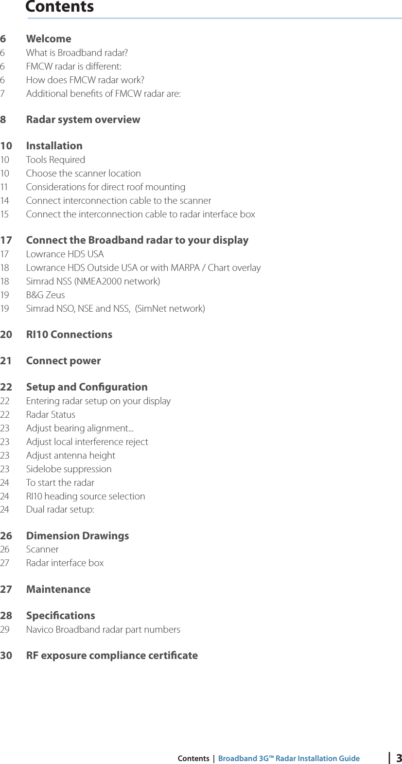
Contents
- 1. Users Manual
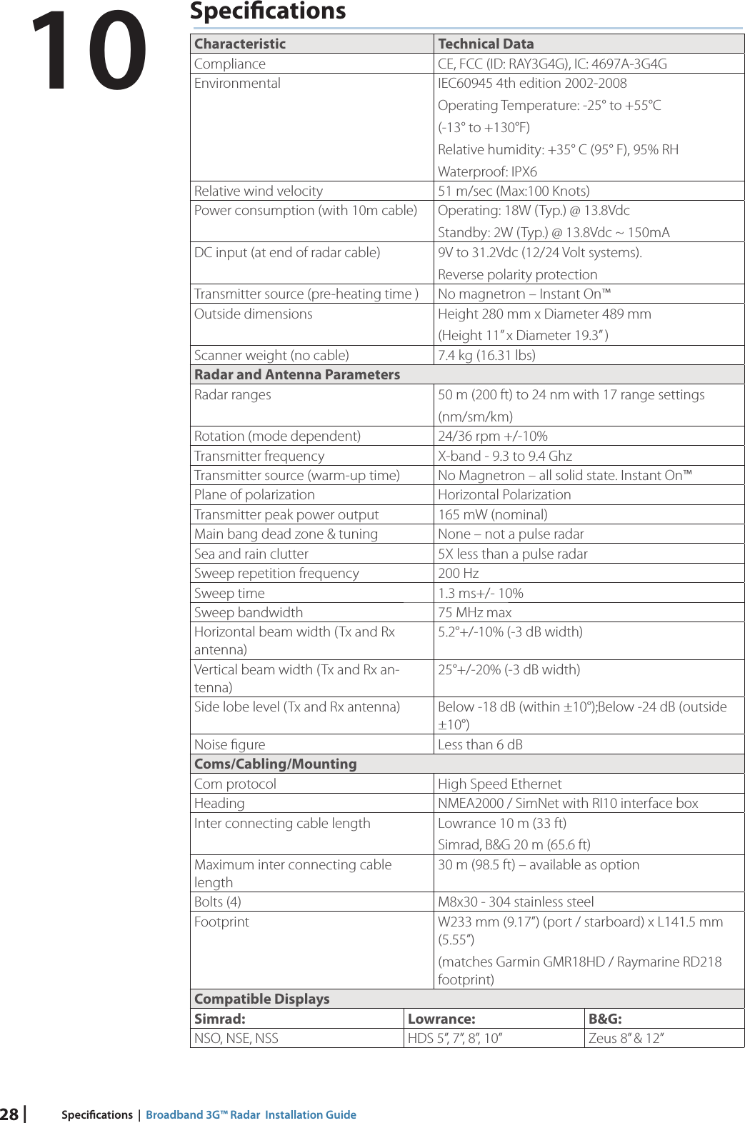
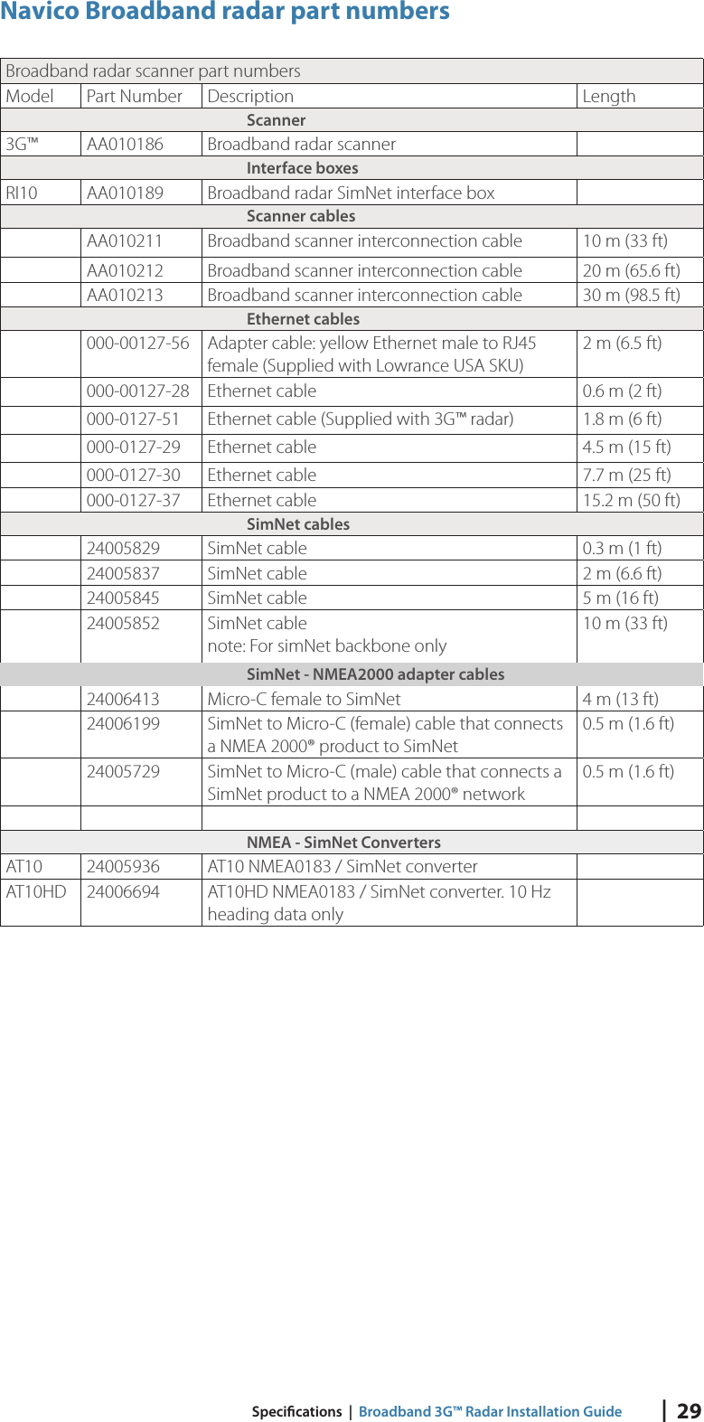
- 2. Radar Specifications 3G
- 3. Radar Specifications 4G
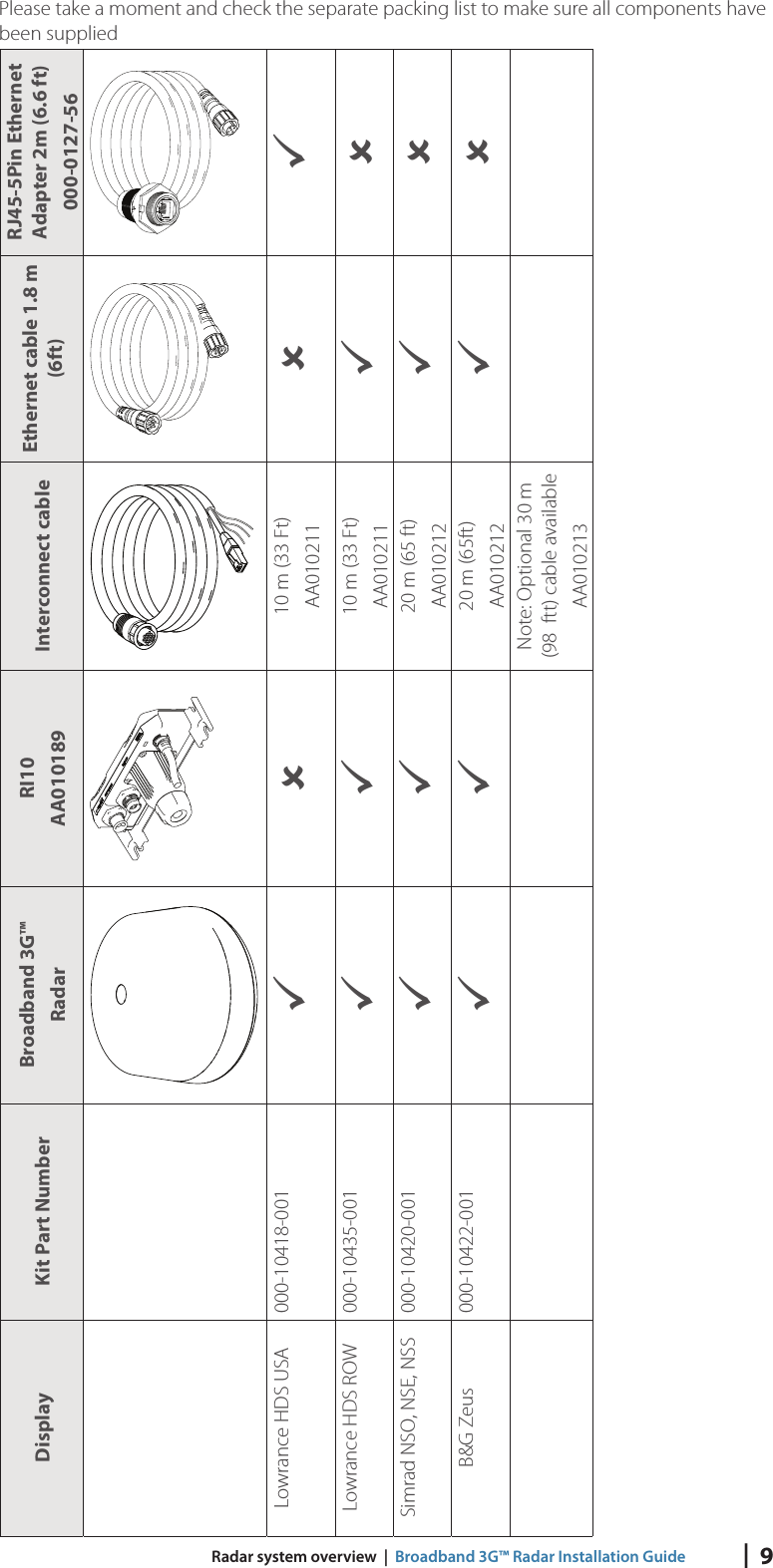
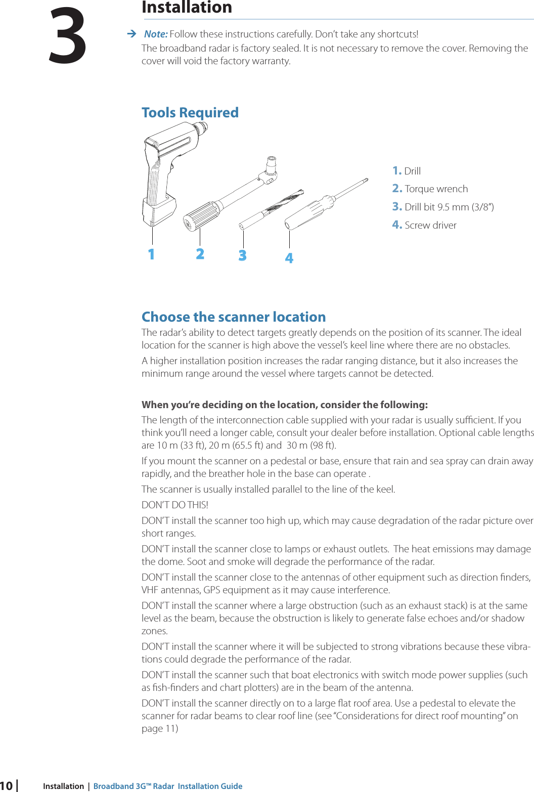
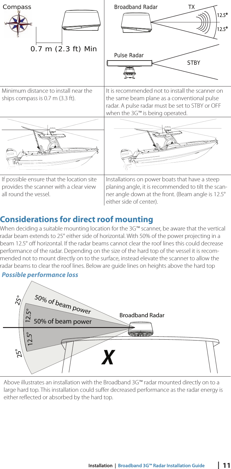
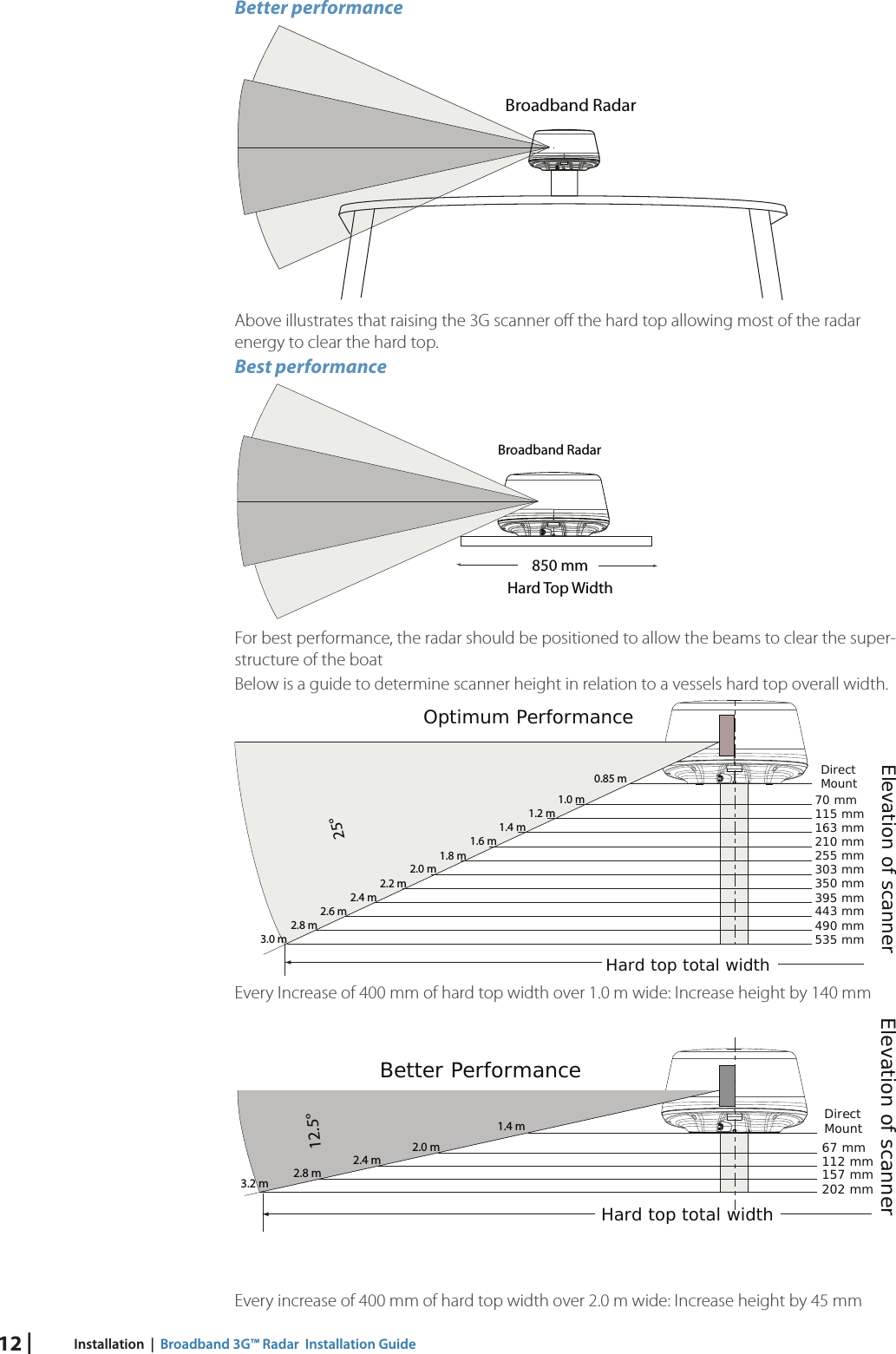
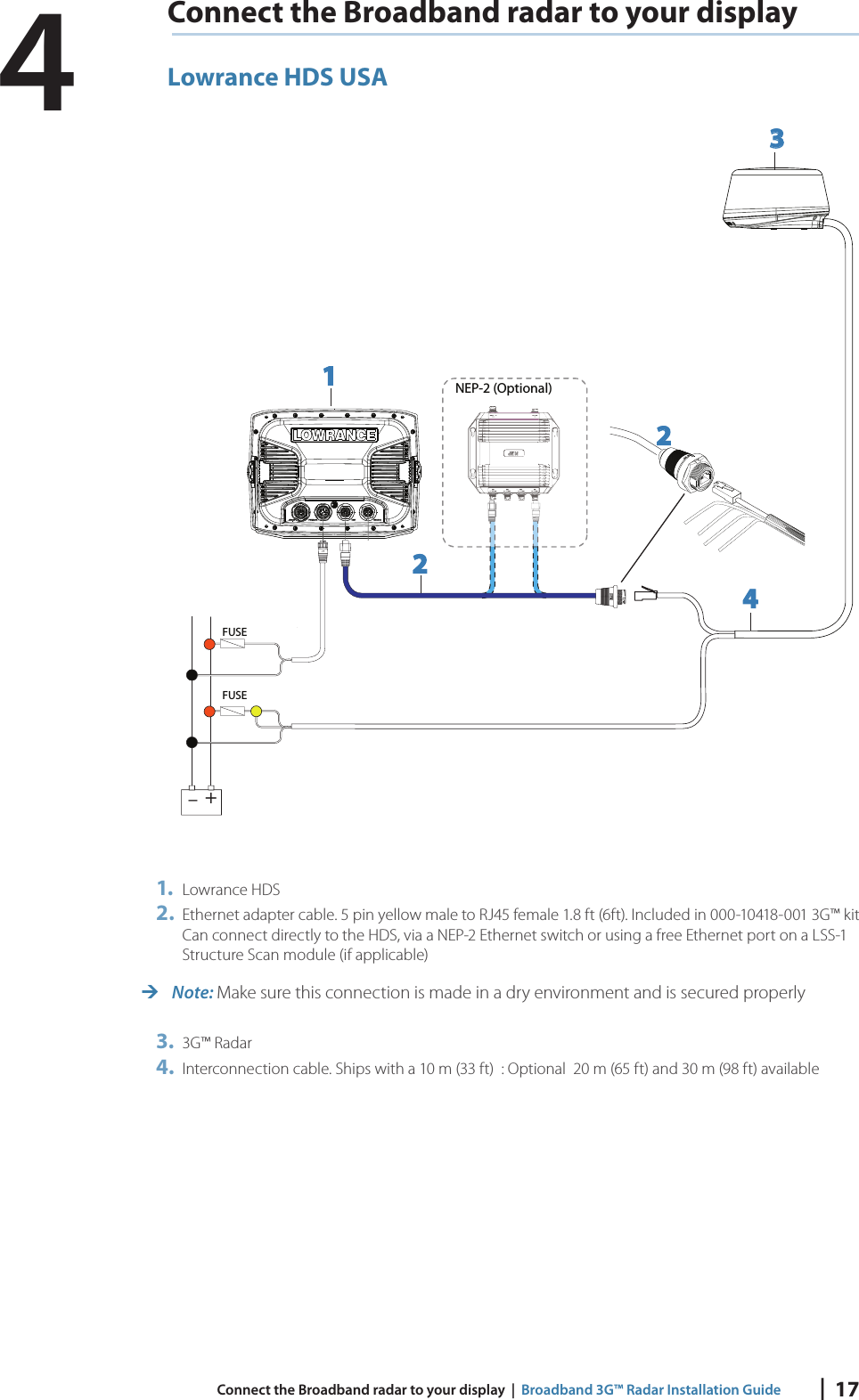
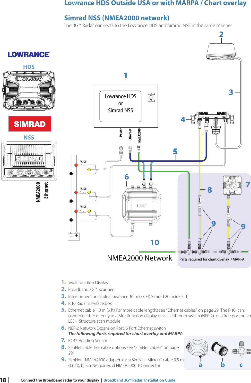
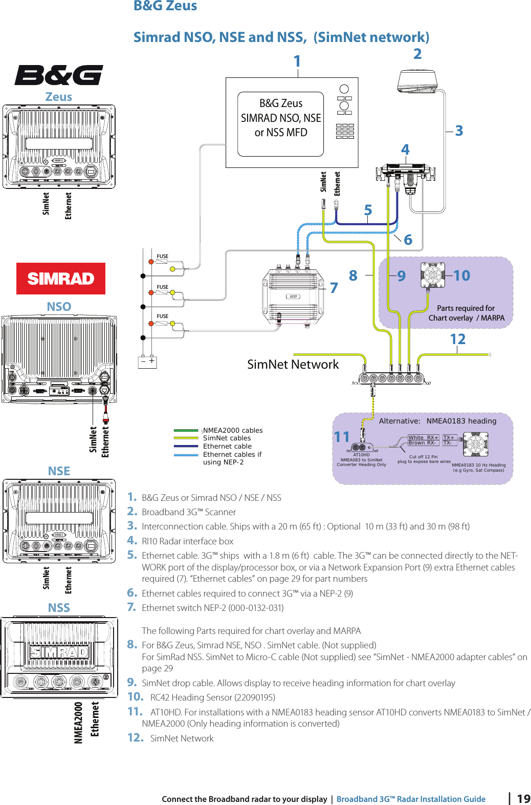
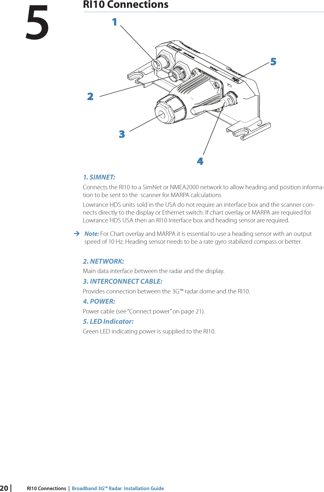
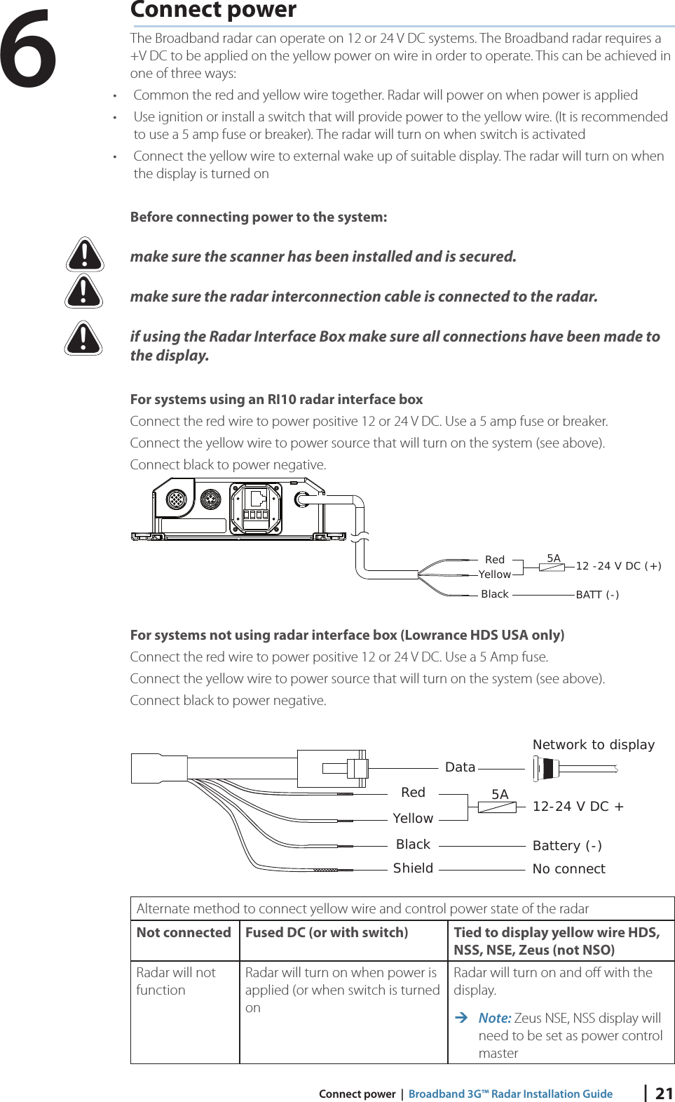
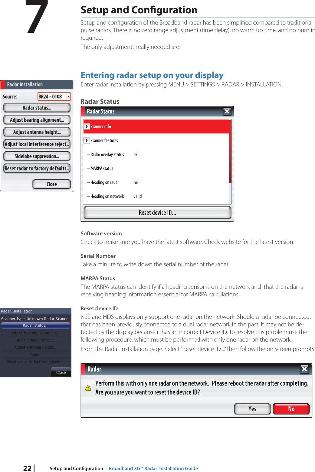
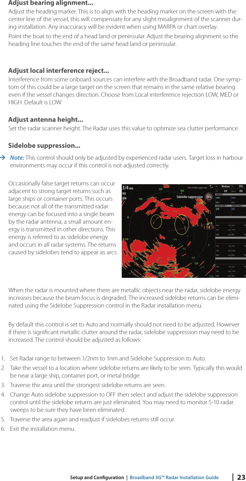
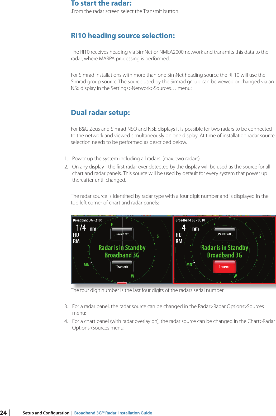
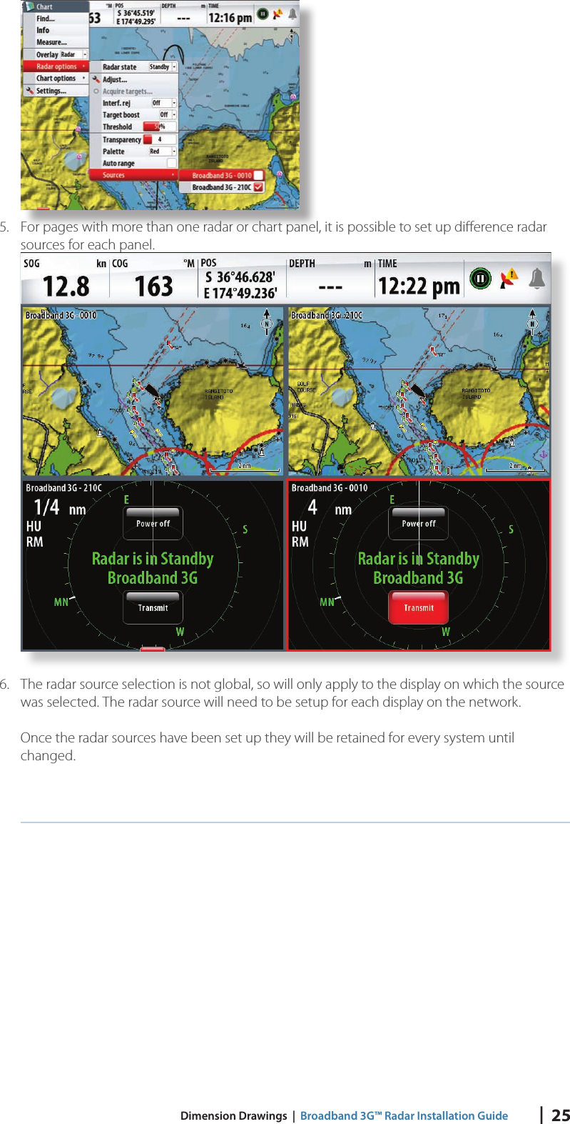
Users Manual