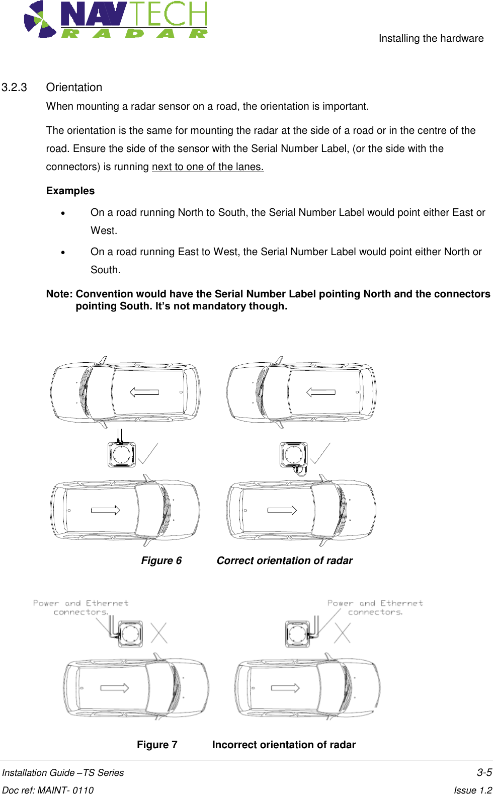
Navtech Radar TS350X-001 TS350-X Position Sensing Radar User Manual Installation Guide TS Series Radar
Navtech Radar Ltd TS350-X Position Sensing Radar Installation Guide TS Series Radar
UserManual.wiki
>
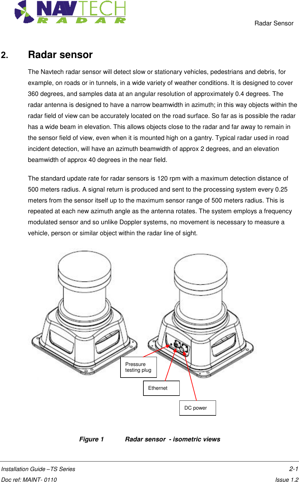
Navtech Radar
>
TS350X-001 User Manual
>
User Guide 1
Contents
1.
User Guide 1
2.
User Guide 2
User Guide 1
Navigation menu
Upload a User Manual
Namespaces
Wiki Guide
HTML
PDF
Info
Views
User Manual
Discussion / Help
Navigation
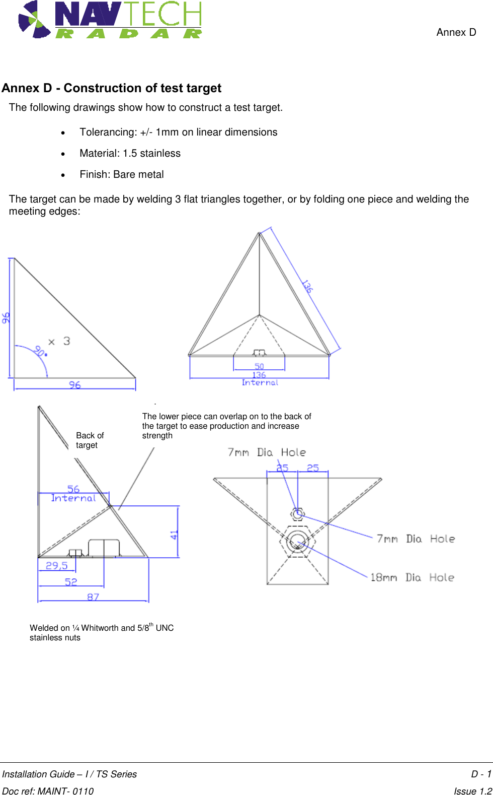
![Introduction Installation Guide –TS Series 1-1 Doc ref: MAINT- 0110 Issue 1.2 1. Introduction 1.1 Scope The Navtech Clearway Automatic Incident Detection system provides an automatic monitoring solution for highways incident detection and traffic management. The Clearway system comprises a high frequency radar sensor, linked to a software system, witness. This guide provides instruction for the radar sensor installation ONLY. The installation of the witness application is covered separately in [2]. Service and Maintenance procedures are also covered separately in [3]. The instructions in this guide are applicable to the following Navtech radar sensors: TS 350-X TS 200-X Details are provided for all the hardware components required for the installation. 1.2 Essential Items The following are essential additional items that you need to install a radar sensor: (i) Electrical Power Electrical power (110 to 230vAC) sourced from, for example, local mains, petrol generator, Pure Sine wave DC to AC convertor,(powered by a vehicle). - 110 to 230vAC power is required for the Radar’s 24vDC PSU. - 110 to 230vAC power is also required for the Laptop Computer. Note: Radars are network intensive. Some laptops reduce the performance of their network connection when only running on their internal battery. (ii) A way of working safely at height Most radars are mounted at a height of 4 to 5m, so some form of equipment or machine is required. You will need one of the following: - Podium steps - MEWP (Mobile Elevated Work Platform) / Cherry Picker / Sky Lift (iii) Laptop computer The laptop must have: - RJ45 Ethernet connection. - 9 pin Com port or USB to RS232 adapter - Software – SPxRadarViewLite-V1.47.1 or higher - Serial communication software – e.g. HyperTerminal, TeraTerm, Putty.](https://usermanual.wiki/Navtech-Radar/TS350X-001.User-Guide-1/User-Guide-1970751-Page-6.png)
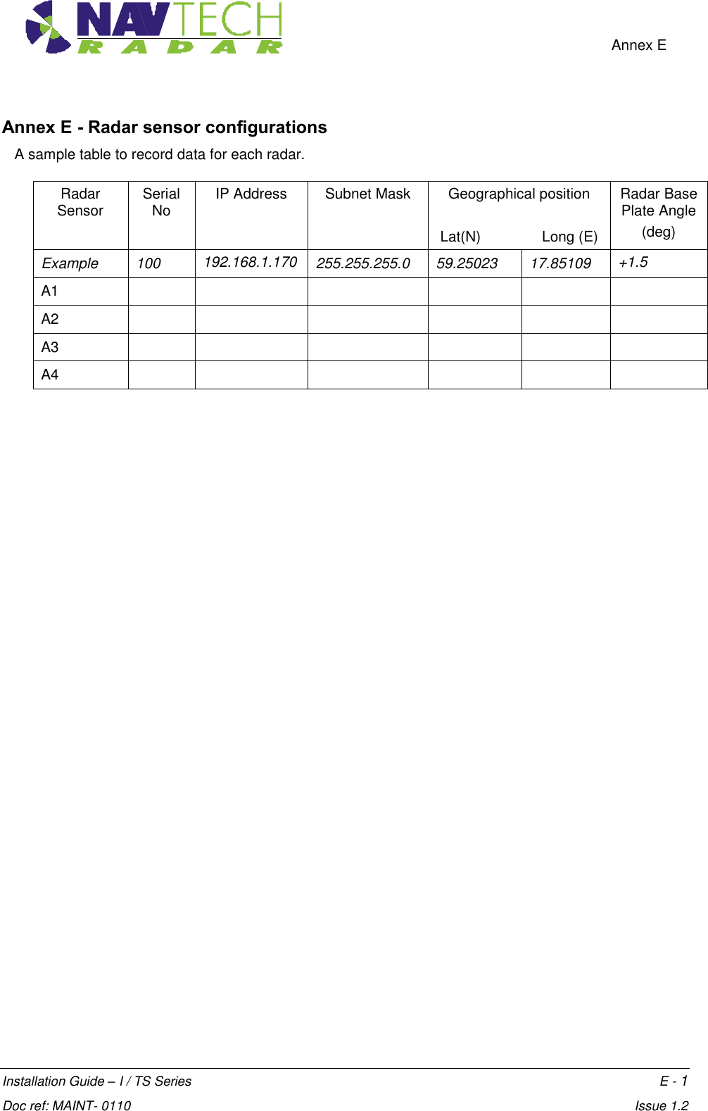
![Introduction Installation Guide –TS Series 1-2 Doc ref: MAINT- 0110 Issue 1.2 (iv) Cat5E shielded patch lead (or Cross over cable, if laptop doesn’t have Auto-MDIX) (v) M10 nuts and bolts for mounting radar The minimum for one radar, in A4 Stainless Steel. - x4 off M10x80 HEX Set Screw - x4 off M10 spring washers - x4 off M10 plain washers - x4 off Nyloc Nuts - x12 off M10 Full plain nuts - x2 off 17mm Spanner for the M10 nuts and bolts above. (vi) 5m tape measure (vii) Digital Level1 (viii) X2 off 25m² Radar Target and tripod (ix) Pair of 2 way radios (x) An assistant (xi) Handheld GPS (Optional) (xii) Power Supply cable (Minimum Requirement) - see Annex C - Table 1 for specification, or Inline Radar Power, Serial and Current Cable (Optional) - see [3]. 1.3 Pre requisites 1. If required, get permission to carry out the work, from the company or organisation that is responsible for the road that you are going to be installing on, or next to. 2. Consider what Traffic Management (TM) is required to perform the installation safely. 3. Before going out to the roadside, power up the radar and connect the laptop that is going to be used, to check that you have both Ethernet and Serial communications. 1 Recommended Fisco Solatronic EN17](https://usermanual.wiki/Navtech-Radar/TS350X-001.User-Guide-1/User-Guide-1970751-Page-7.png)
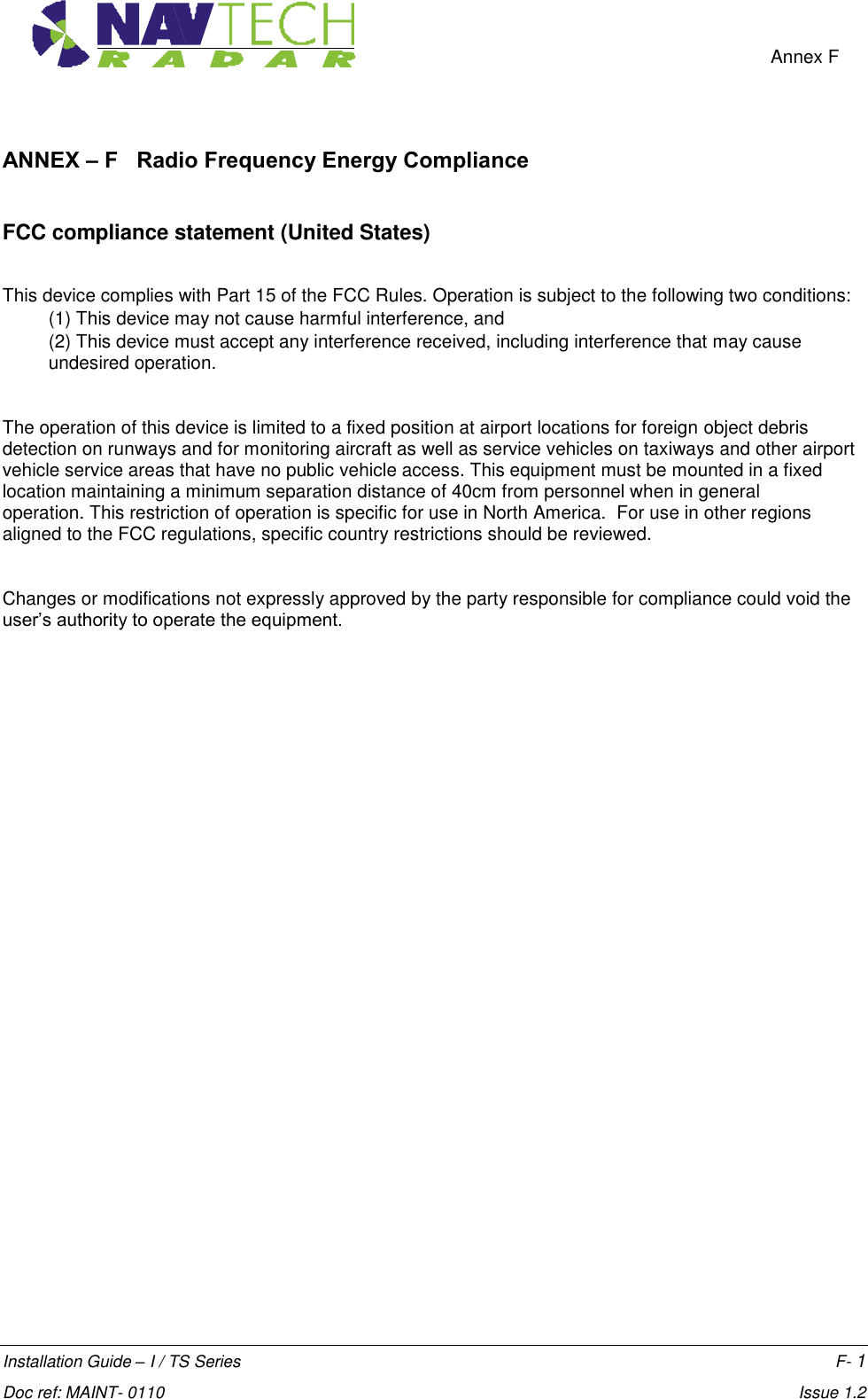
![Radar Sensor Installation Guide –TS Series 2-2 Doc ref: MAINT- 0110 Issue 1.2 Figure 2 Radar sensor - dimensions See [D1] for further details on the radar housing. See the relevant datasheet [6] to [7] for the radar sensor.](https://usermanual.wiki/Navtech-Radar/TS350X-001.User-Guide-1/User-Guide-1970751-Page-9.png)
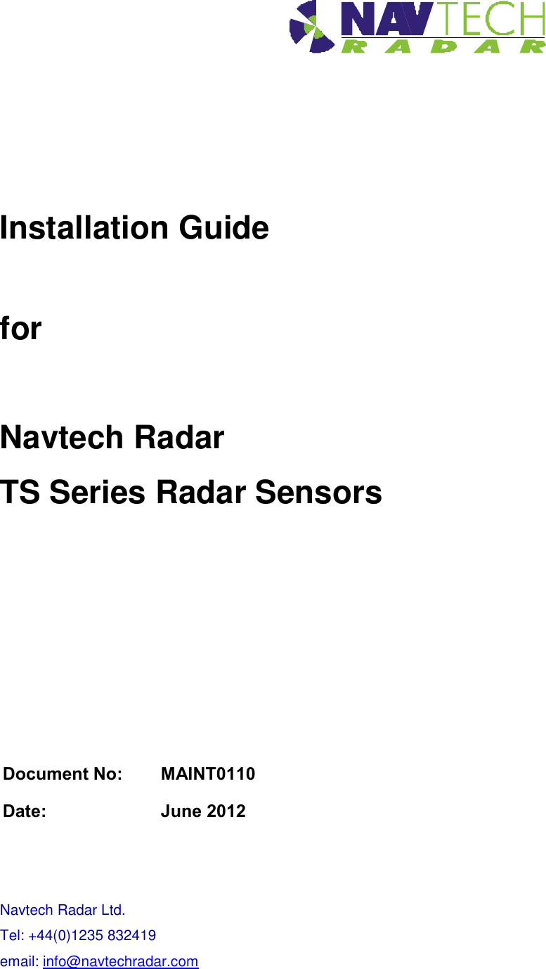
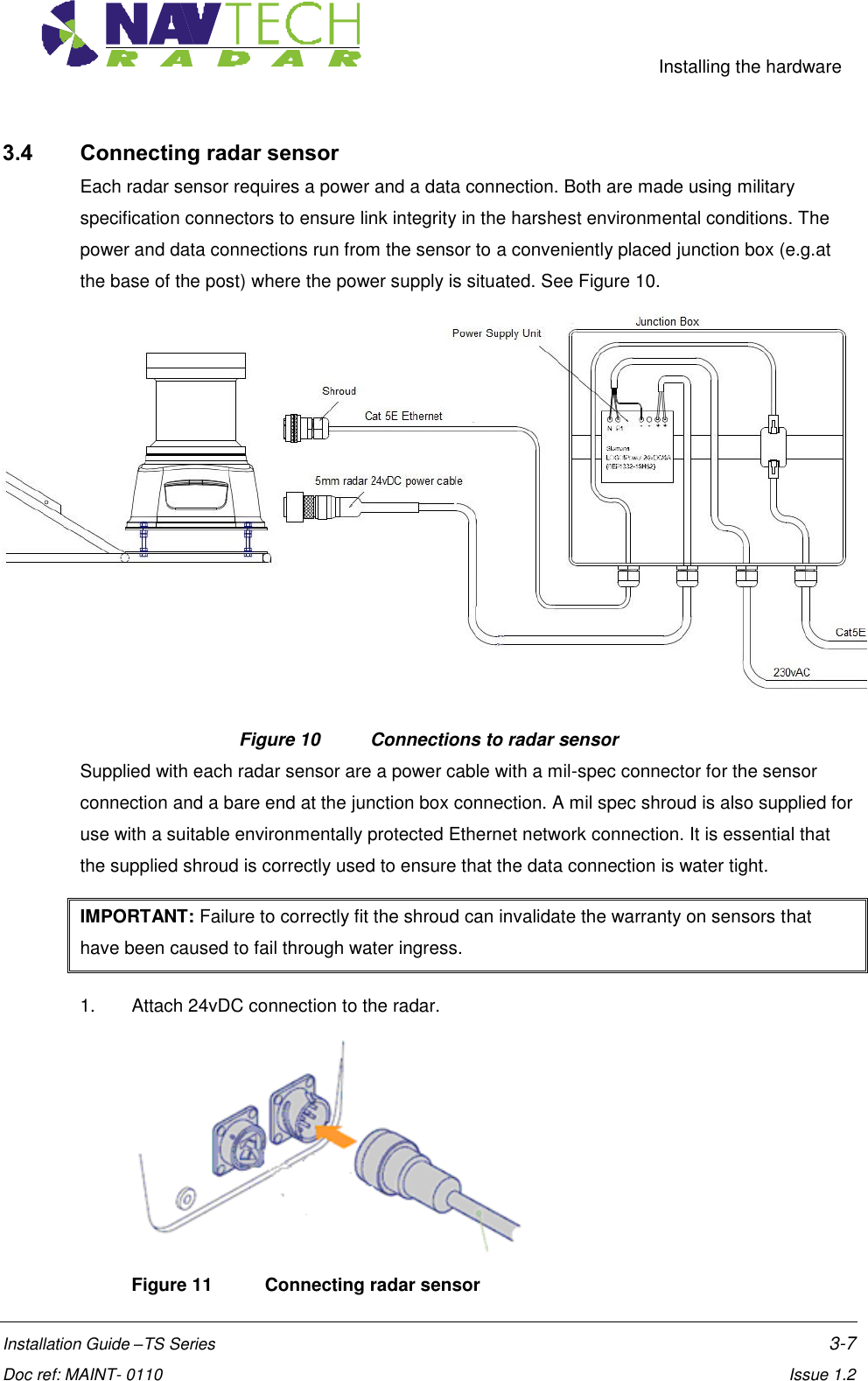
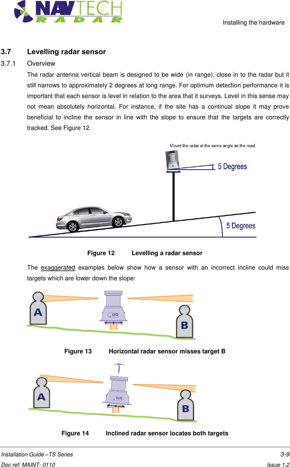
![Installing the hardware Installation Guide –TS Series 3-1 Doc ref: MAINT- 0110 Issue 1.2 3. Installing the Radar hardware 3.1 Overview This section details the installation process, which comprises the following steps: 1. Determine radar sensor locations 2. Mount radar 3. Connect radar sensor 4. Prepare laptop 5. Connect laptop 6. Level radar sensor 7. Install Navtech witness software 8. Confirm sensor coverage Note: The installation and configuration of the witness software is covered separately in [2]. CAUTION Before performing any installation task ensure you are aware of Health & Safety procedures. (See Section 4)](https://usermanual.wiki/Navtech-Radar/TS350X-001.User-Guide-1/User-Guide-1970751-Page-10.png)
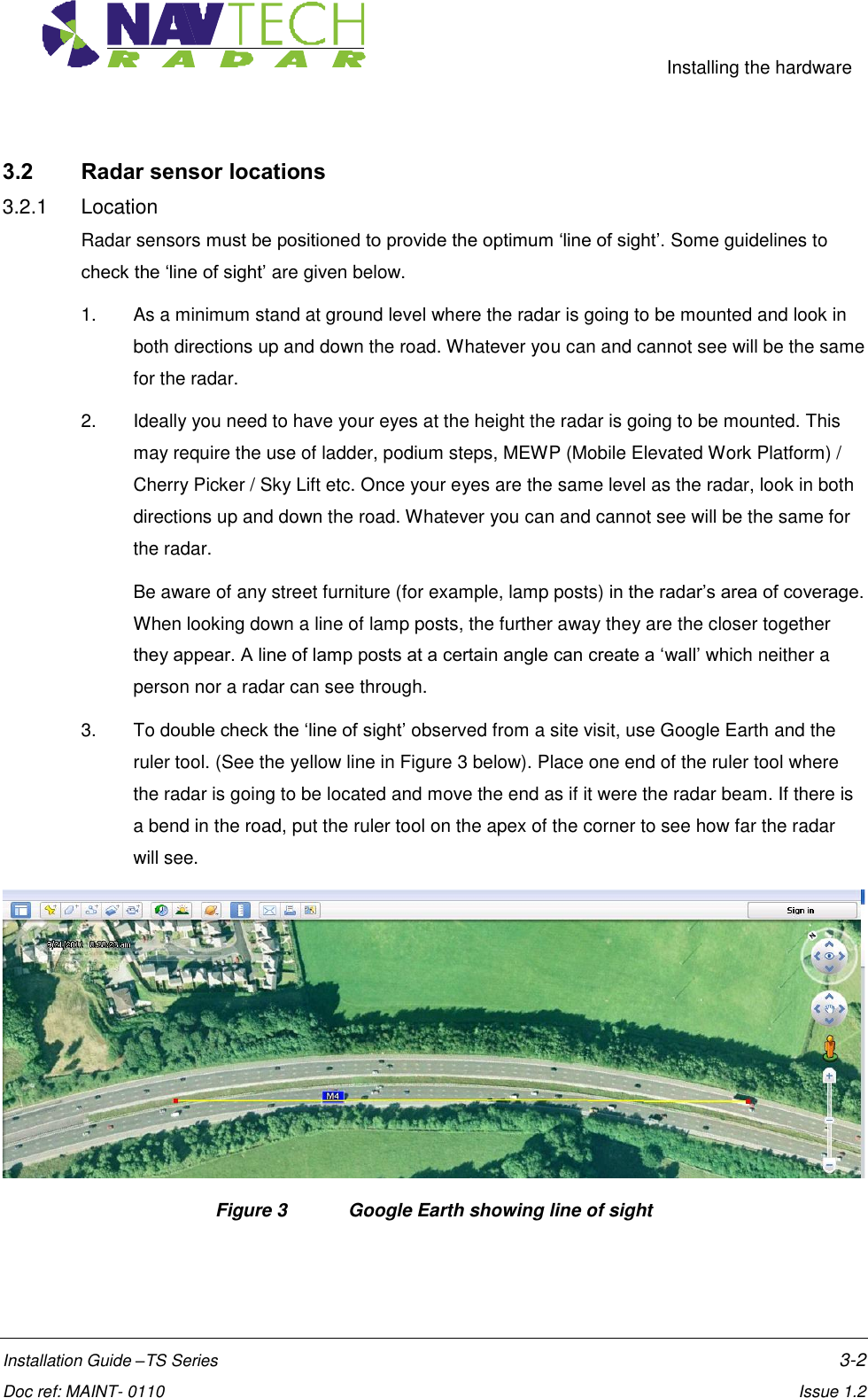
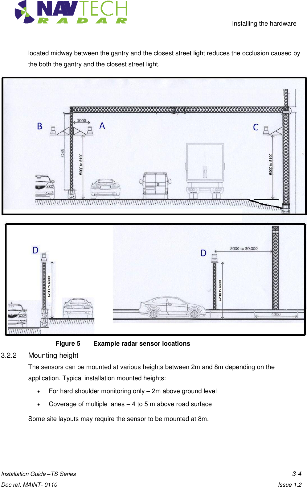
![Installing the hardware Installation Guide –TS Series 3-3 Doc ref: MAINT- 0110 Issue 1.2 In a straight line the radar can detect a person from 20m away to 350m away. If the person is closer than 20m they will be below the radar and further than 350m away, they are too small for the radar to detect. However, if the road curves, the radar cannot detect people, cars, etc. out of sight around the bend. This must be taken into account when calculating the number of radar required to provide complete coverage. Be aware that for slow or stopped vehicles, a stopped car that ultimately comes to rest directly beneath the radar will slow down well before this point. The slow vehicle alarm will be raised in this case. Reducing the radar mounting height can increase coverage close in to the radar. See [D2]. Figure 4 shows the radar mounted at 4m giving coverage to the ground of approximately16.25 m. Figure 4 Radar coverage (mounted at 4 metres) Refer 3.2.2 for typical installation mounting heights. Example Consider the positions of radar sensors used to provide coverage on a road. The position of the radar is determined by how straight or curved the road is either side of the mounting post/gantry and what affect the neighbouring street lights may have on the radar’s ‘line of sight’. When you have a line of street lights on a curve they can have the effect of creating a barrier the radar cannot see through. Moving the radar from one side to the other side of the central barrier can have a dramatic effect on improving the radar line of sight. In more extreme cases moving the radar to the roadside would be required. In this example, each radar has a possible four locations on, or near, a gantry on the road. See Figure 5 below. If the road has a shallow curve, radar Position A or B is selected. If the road has a pronounced curve, radar Position C is selected - where C is the outside of the curve. If the road is absolutely straight, the radar is mounted on a post (Position D). Having the radar on a post](https://usermanual.wiki/Navtech-Radar/TS350X-001.User-Guide-1/User-Guide-1970751-Page-12.png)
![Installing the hardware Installation Guide –TS Series 3-6 Doc ref: MAINT- 0110 Issue 1.2 3.3 Mounting radar sensor Radar sensors may be mounted on dedicated posts, or various other structures (e.g walls, roofs, gantries) using brackets. Sample posts and brackets are shown in Annex B. Radar sensors are fitted to a plate on top of the post, or on the bracket, using nuts and bolts, which allows you to adjust the tilt [See Figure 8 ]. Adjusting the tilt (levelling the sensor) ensures optimum detection performance and is detailed in Section 3.7. Figure 8 Mounting plate on post / bracket The sensor mounting plate (or bracket) design allows for a simple yet effective method to fine tune the incline of the sensor. For each of the mounting holes, the bolt is fed from underneath and locked onto the mounting plate with a nut. Two more nuts are used below the radar base plate and another is used above so that the sensor can be positioned anywhere up or down the bolt thread, as necessary. Figure 9 Levelling adjustment 1. Place the radar on the threaded studs of the plate. Bracket Post](https://usermanual.wiki/Navtech-Radar/TS350X-001.User-Guide-1/User-Guide-1970751-Page-15.png)
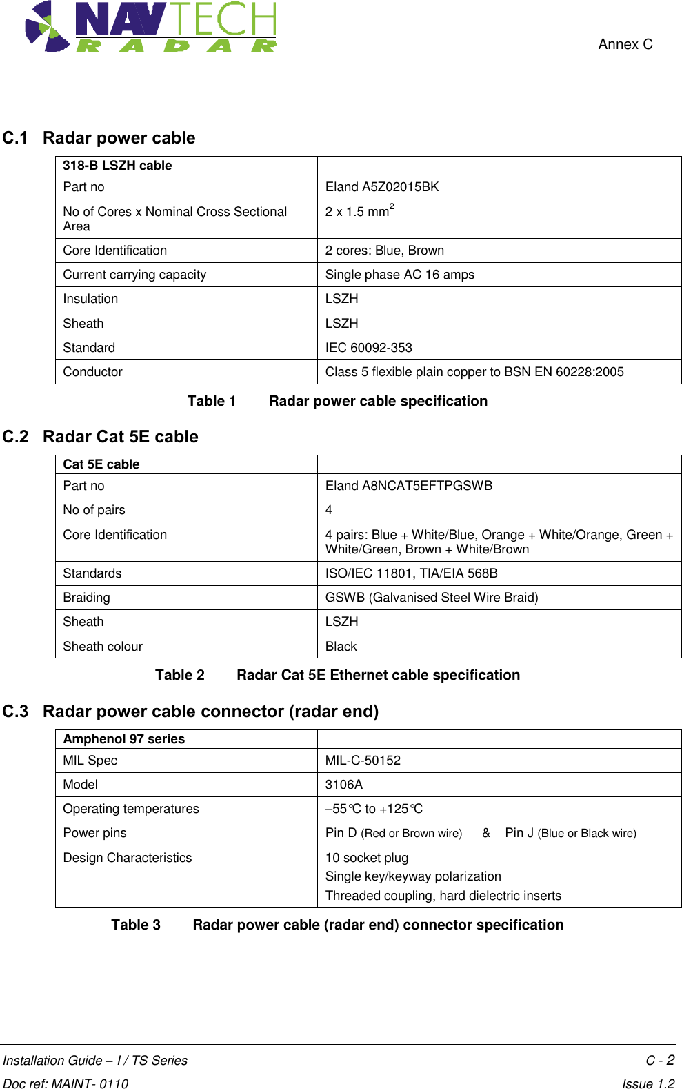
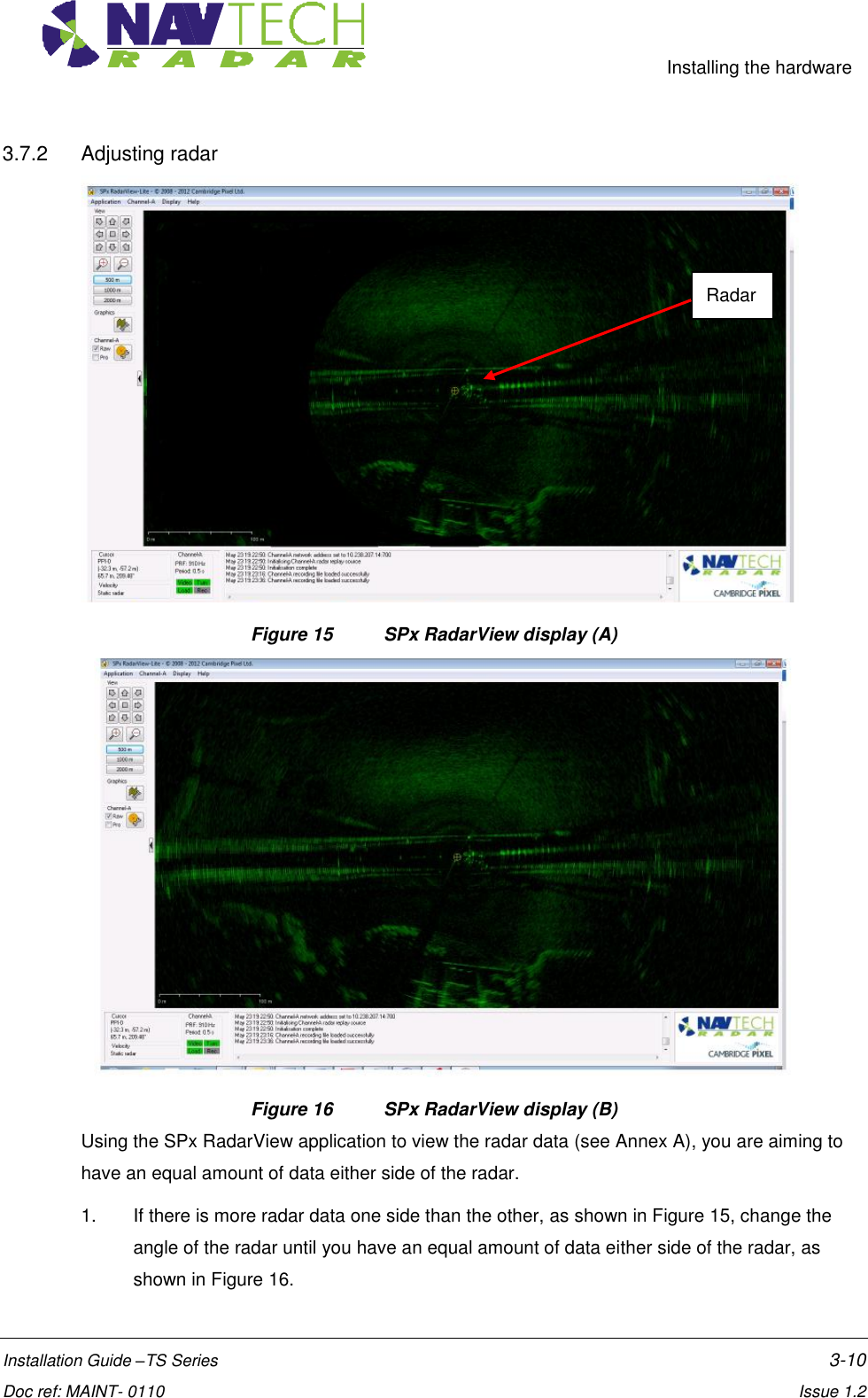
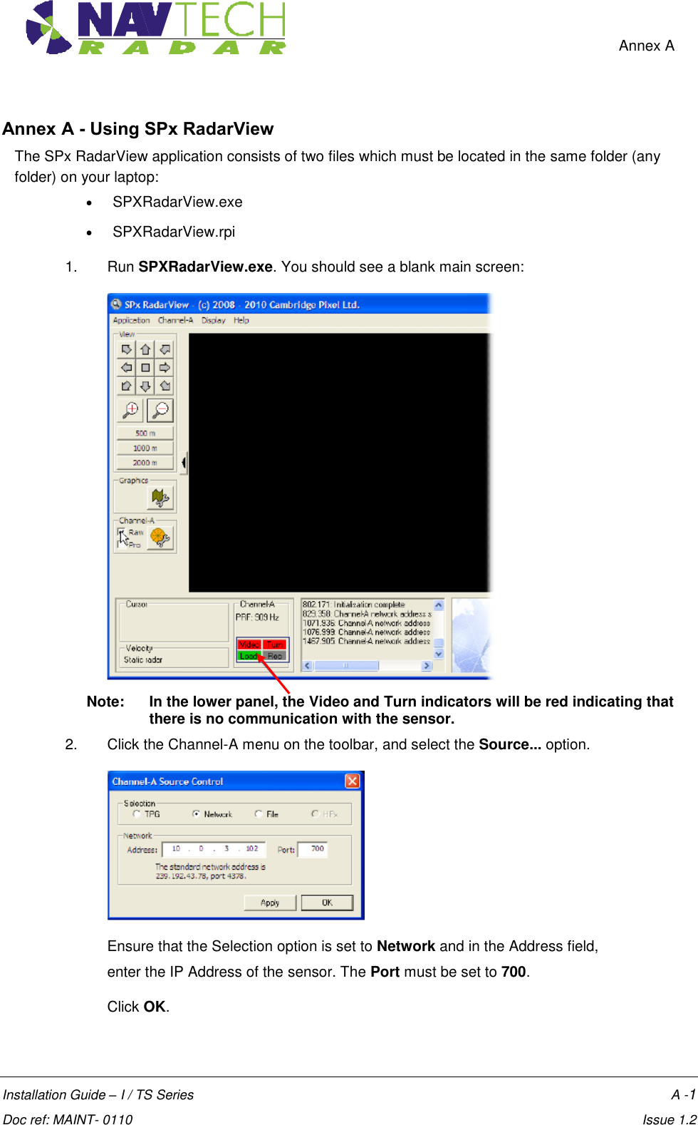
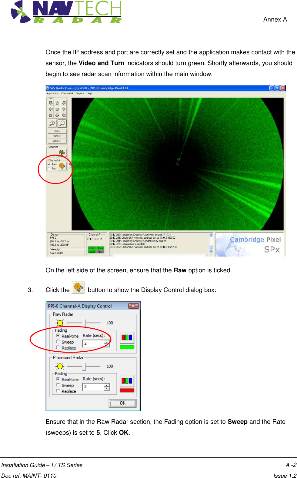
![Installing the hardware Installation Guide –TS Series 3-8 Doc ref: MAINT- 0110 Issue 1.2 2. Ensure the Power and Ethernet cables are securely connected into junction box. 3. Ensure the junction box has the Navtech supplied 24vDC power supply installed. (The power supply unit has a peak current capacity of 4 Amps, though typically the radar draws a continuous 1 Amp). See.[8]. 4. Ensure that the Power supply cabling is correctly terminated at the radar end with a secure Amphenol MIL spec connector. Pin D (Red or Brown) is 24vDC, Pin J (Blue or Black) is 0V. IMPORTANT: To prevent floating voltage levels on the low output of the radar sensor power supply unit, link the 0v output to earth. 5. Ensure the junction box has an Ethernet cable running to the infrastructure network switch. 3.5 Preparing the laptop IMPORTANT: Ensure that your laptop has its IP address set to operate within the same subnet as the radar sensor 3.5.1 Factory settings The IP address (e.g. 192.168.0.1) of the radar sensor is preset before leaving Navtech Radar Limited according to client specifications and will be declared on a label attached to the outer casing. The subnet mask of the radar sensor is often preset to 255.255.255.0 but could also be set wider (such as 255.255.0.0) if requested. Therefore, if the sensor IP address is 192.168.0.1 and the mask is 255.255.255.0, then your computer must use an IP address in the range: 192.168.0.2 to 192.168.0.254. 3.5.2 Changing factory settings The IP address and subnet mask can be changed using firmware commands sent to the radar either via Telnet (see [5]), or using a serial connection (see [D3]). 3.6 Connecting your laptop 1. At the radar, connect the laptop via CAT5 cable to the radar. 2. Ensure that the radar sensor is powered on and is rotating - you can faintly hear the rotor when it is running. 3. Use SPx Radar View application [1] to display the radar data. (See Annex A )](https://usermanual.wiki/Navtech-Radar/TS350X-001.User-Guide-1/User-Guide-1970751-Page-17.png)
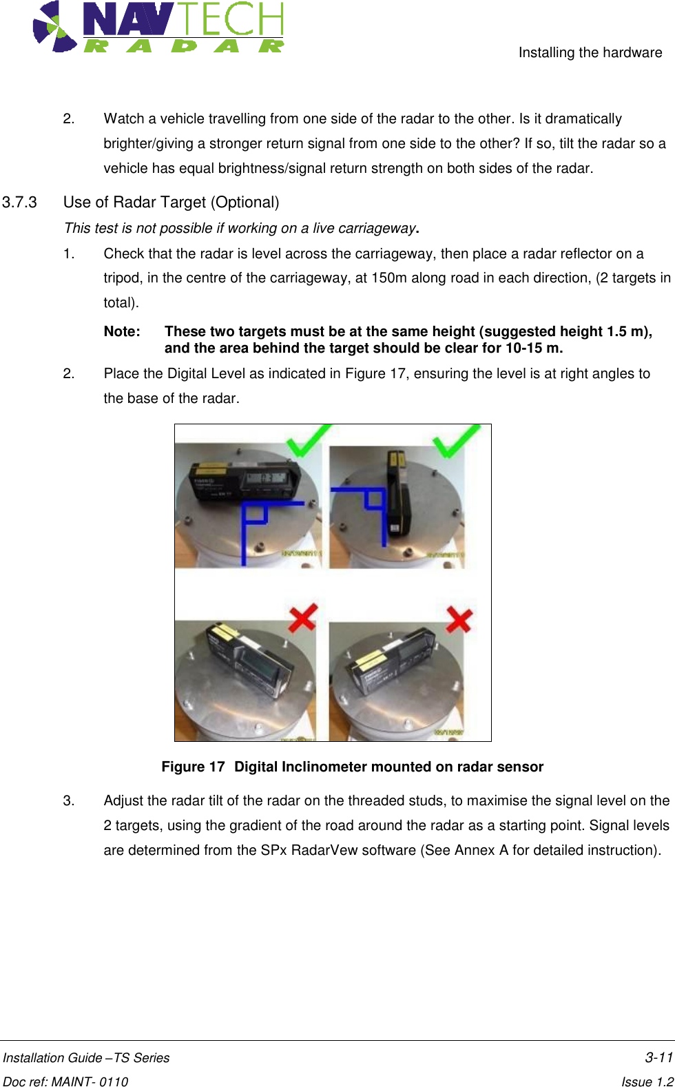
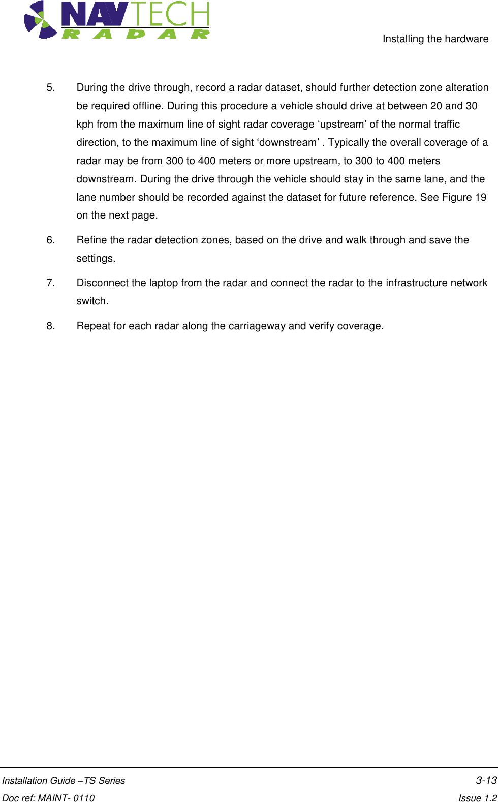
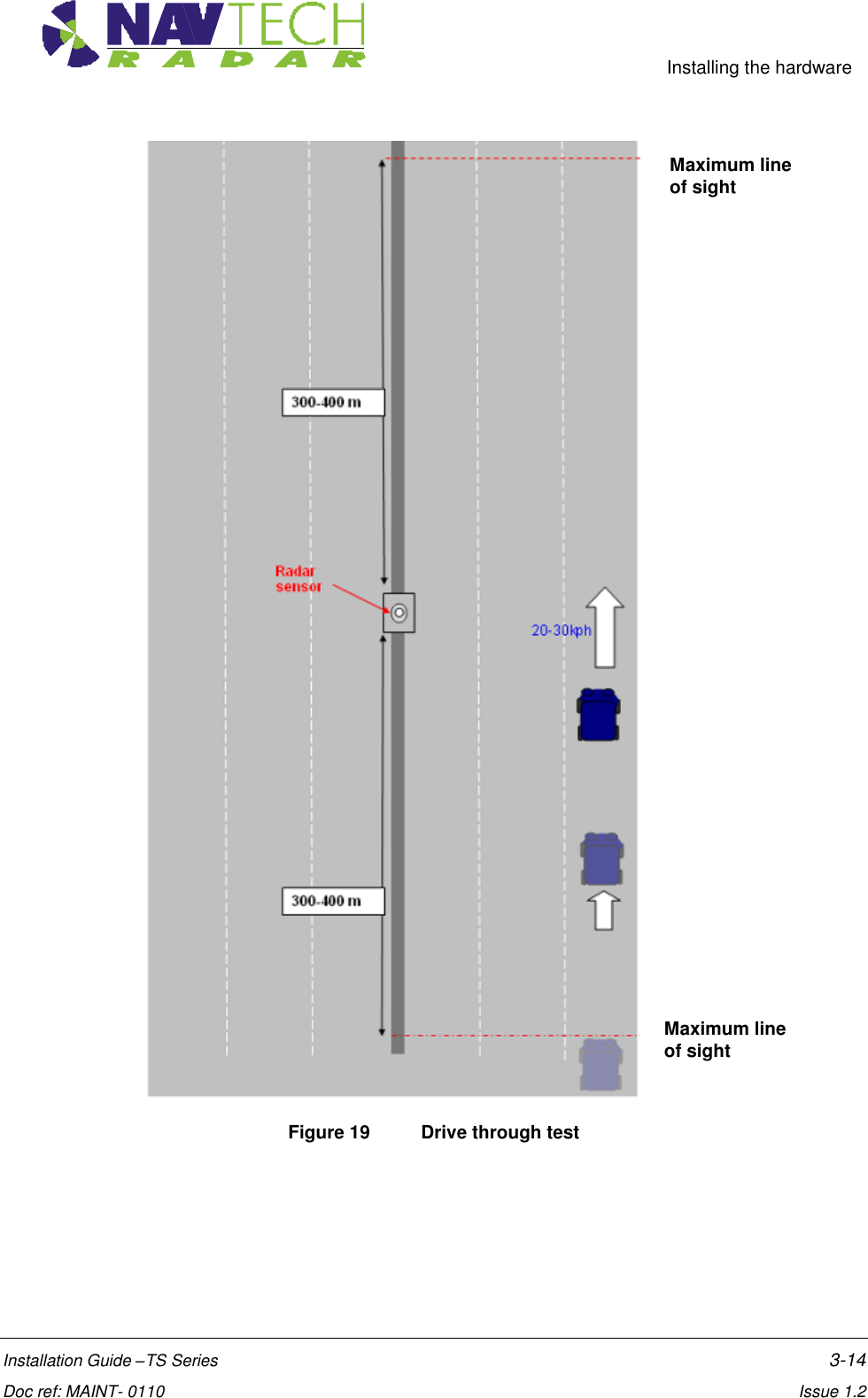
![Installing the hardware Installation Guide –TS Series 3-12 Doc ref: MAINT- 0110 Issue 1.2 Figure 18 Radar view to locate target 3.8 Securing the radar 1. Secure the radar on the mounting bracket, or post plate. To do this: lock off the two lower nuts on each stud by tightening one against the other. (This is to ensure that, if the radar is removed, the tilt angle is not changed) 2. Record the tilt angle from the digital inclinometer. See Annex E for a sample table. 3.9 Confirming sensor coverage 1. Install and configure the witness software as described in [2]. 2. Enter basic detection areas into Sentinel. (See [2]). 3. Perform a basic walk through tests of the radar and monitor the tracking performance along the carriageway, within radar line of site. See [4] for instruction on how to monitor the performance. 4. Perform a drive through test of this radar. Monitor the tracking performance along the carriageway, within radar line of site as this test is conducted.](https://usermanual.wiki/Navtech-Radar/TS350X-001.User-Guide-1/User-Guide-1970751-Page-21.png)

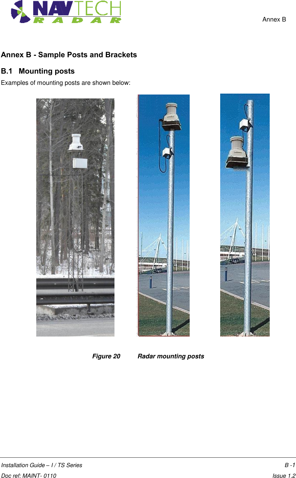
![Annex B Installation Guide – I / TS Series B -2 Doc ref: MAINT- 0110 Issue 1.2 B.2 Mounting brackets Typical radar sensor mounting brackets: See [D4] for dimensions. Figure 21 Mounting brackets](https://usermanual.wiki/Navtech-Radar/TS350X-001.User-Guide-1/User-Guide-1970751-Page-31.png)