Navtech Radar TS350X-001 TS350-X Position Sensing Radar User Manual Installation Guide TS Series Radar
Navtech Radar Ltd TS350-X Position Sensing Radar Installation Guide TS Series Radar
Contents
- 1. User Guide 1
- 2. User Guide 2
User Guide 1


Document History
Installation Guide –TS Series i
Doc ref: MAINT- 0110 Issue 1.2
Document History
Issue
Date
Description
1.0
01/06/2012
First Draft
1.1
18/03/2013
Update for FCC statement
1.2
20/03/2013
Updated the FCC statement

Contents
Installation Guide –TS Series ii
Doc ref: MAINT- 0110 Issue 1.2
Contents
Document History i
List of figures iii
List of tables iii
Referenced Documents iv
Drawings List iv
1. Introduction 1-1
1.1 Scope 1-1
1.2 Essential Items 1-1
1.3 Pre requisites 1-3
2. Radar sensor 2-1
3. Installing the Radar hardware 3-1
3.1 Overview 3-1
3.2 Radar sensor locations 3-2
3.2.1 Location 3-2
3.2.2 Mounting height 3-4
3.2.3 Orientation 3-5
3.3 Mounting radar sensor 3-6
3.4 Connecting radar sensor 3-7
3.5 Preparing the laptop 3-8
3.5.1 Factory settings 3-8
3.5.2 Changing factory settings 3-8
3.6 Connecting your laptop 3-9
3.7 Levelling radar sensor 3-9
3.7.1 Overview 3-9
3.7.2 Adjusting radar 3-11
3.7.3 Use of Radar Target (Optional) 3-12
3.8 Securing the radar 3-13
3.9 Confirming sensor coverage 3-13
4. Health & Safety 4-1
4.1.1 General 4-1
4.1.2 Design 4-1
4.1.3 Maintenance 4-1
Annex A - Using SPx RadarView
Annex B - Sample Posts and Brackets
Annex C - Specifications
Annex D - Construction of test target
Annex E - Radar sensor configurations

Contents
Installation Guide –TS Series iii
Doc ref: MAINT- 0110 Issue 1.2
List of figures
Figure 1 Radar sensor - isometric views ....................................................................................... 2-1
Figure 2 Radar sensor - dimensions .............................................................................................. 2-2
Figure 3 Google Earth showing line of sight .................................................................................. 3-2
Figure 4 Radar coverage (mounted at 4 metres) ........................................................................... 3-3
Figure 5 Example radar sensor locations ....................................................................................... 3-4
Figure 6 Correct orientation of radar .............................................................................................. 3-5
Figure 7 Incorrect orientation of radar ............................................................................................ 3-5
Figure 8 Mounting plate on post / bracket ...................................................................................... 3-6
Figure 9 Levelling adjustment ........................................................................................................ 3-6
Figure 10 Connections to radar sensor ............................................................................................ 3-7
Figure 11 Connecting radar sensor .................................................................................................. 3-7
Figure 12 Levelling a radar sensor ................................................................................................... 3-9
Figure 13 Horizontal radar sensor misses target B .......................................................................... 3-9
Figure 14 Inclined radar sensor locates both targets ....................................................................... 3-9
Figure 15 SPx RadarView display (A) ............................................................................................ 3-10
Figure 16 SPx RadarView display (B) ............................................................................................ 3-10
Figure 17 Digital Inclinometer mounted on radar sensor ............................................................... 3-11
Figure 18 Radar view to locate target ............................................................................................ 3-12
Figure 19 Drive through test ........................................................................................................... 3-14
Figure 20 Radar mounting posts ..................................................................................................... B -1
Figure 21 Mounting brackets .......................................................................................................... B -2
Figure 22 TS 350-X mounted on a wall ........................................................................................... B -3
List of tables
Table 1 Radar power cable specification ..................................................................................... C -2
Table 2 Radar Cat 5E Ethernet cable specification ..................................................................... C -2
Table 3 Radar power cable (radar end) connector specification ................................................. C -2
Table 4 Radar Cat 5E cable connector (radar end) specification ................................................ C -3

Referenced Documents
Installation Guide –TS Series iv
Doc ref: MAINT- 0110 Issue 1.2
Referenced Documents
Ref
Title
Supplier
Doc Ref No
1
SPx RadarView-Lite for Windows User
Manual
Cambridge
Pixel
CP-25-127-03
2
Clearway witness Commissioning
Guide
Navtech
3
Navtech Service & Maintenance
Manual I-TS Series Radar
Navtech
MAINT 0010
4
Clearway witness Operating Guide
Navtech
5
Entry and User Level Firmware
Commands for all W, I and AGS
Series
Navtech
RND – S0069
6
TS 350-X Datasheet
Navtech
7
TS 200-X Datasheet
Navtech
8
Power Supply unit datasheet
Siemens
https://support.automation.siemens.com
6EP1332-1SH52 Data sheet
Drawings List
Ref
Drawing No
Title
D1
ASM 0031
Radar Housing
D2
SIT 0055
Mounting Height Comparison
D3
SUB 0119
Inline Power and Serial Cable
D4
MBP 0260
Steel bracket

Introduction
Installation Guide –TS Series 1-1
Doc ref: MAINT- 0110 Issue 1.2
1. Introduction
1.1 Scope
The Navtech Clearway Automatic Incident Detection system provides an automatic monitoring
solution for highways incident detection and traffic management. The Clearway system
comprises a high frequency radar sensor, linked to a software system, witness. This guide
provides instruction for the radar sensor installation ONLY. The installation of the witness
application is covered separately in [2]. Service and Maintenance procedures are also covered
separately in [3].
The instructions in this guide are applicable to the following Navtech radar sensors:
TS 350-X
TS 200-X
Details are provided for all the hardware components required for the installation.
1.2 Essential Items
The following are essential additional items that you need to install a radar sensor:
(i) Electrical Power
Electrical power (110 to 230vAC) sourced from, for example, local mains,
petrol generator, Pure Sine wave DC to AC convertor,(powered by a
vehicle).
- 110 to 230vAC power is required for the Radar’s 24vDC PSU.
- 110 to 230vAC power is also required for the Laptop Computer.
Note: Radars are network intensive. Some laptops reduce the performance of their
network connection when only running on their internal battery.
(ii) A way of working safely at height
Most radars are mounted at a height of 4 to 5m, so some form of
equipment or machine is required. You will need one of the following:
- Podium steps
- MEWP (Mobile Elevated Work Platform) / Cherry Picker / Sky Lift
(iii) Laptop computer
The laptop must have:
- RJ45 Ethernet connection.
- 9 pin Com port or USB to RS232 adapter
- Software – SPxRadarViewLite-V1.47.1 or higher
- Serial communication software – e.g. HyperTerminal, TeraTerm, Putty.

Introduction
Installation Guide –TS Series 1-2
Doc ref: MAINT- 0110 Issue 1.2
(iv) Cat5E shielded patch lead (or Cross over cable, if laptop doesn’t have Auto-MDIX)
(v) M10 nuts and bolts for mounting radar
The minimum for one radar, in A4 Stainless Steel.
- x4 off M10x80 HEX Set Screw
- x4 off M10 spring washers
- x4 off M10 plain washers
- x4 off Nyloc Nuts
- x12 off M10 Full plain nuts
- x2 off 17mm Spanner for the M10 nuts and bolts above.
(vi) 5m tape measure
(vii) Digital Level
1
(viii) X2 off 25m² Radar Target and tripod
(ix) Pair of 2 way radios
(x) An assistant
(xi) Handheld GPS (Optional)
(xii) Power Supply cable (Minimum Requirement) - see Annex C - Table 1 for specification, or
Inline Radar Power, Serial and Current Cable (Optional) - see [3].
1.3 Pre requisites
1. If required, get permission to carry out the work, from the company or organisation that is
responsible for the road that you are going to be installing on, or next to.
2. Consider what Traffic Management (TM) is required to perform the installation safely.
3. Before going out to the roadside, power up the radar and connect the laptop that is going
to be used, to check that you have both Ethernet and Serial communications.
1
Recommended Fisco Solatronic EN17
Radar Sensor
Installation Guide –TS Series 2-1
Doc ref: MAINT- 0110 Issue 1.2
2. Radar sensor
The Navtech radar sensor will detect slow or stationary vehicles, pedestrians and debris, for
example, on roads or in tunnels, in a wide variety of weather conditions. It is designed to cover
360 degrees, and samples data at an angular resolution of approximately 0.4 degrees. The
radar antenna is designed to have a narrow beamwidth in azimuth; in this way objects within the
radar field of view can be accurately located on the road surface. So far as is possible the radar
has a wide beam in elevation. This allows objects close to the radar and far away to remain in
the sensor field of view, even when it is mounted high on a gantry. Typical radar used in road
incident detection, will have an azimuth beamwidth of approx 2 degrees, and an elevation
beamwidth of approx 40 degrees in the near field.
The standard update rate for radar sensors is 120 rpm with a maximum detection distance of
500 meters radius. A signal return is produced and sent to the processing system every 0.25
meters from the sensor itself up to the maximum sensor range of 500 meters radius. This is
repeated at each new azimuth angle as the antenna rotates. The system employs a frequency
modulated sensor and so unlike Doppler systems, no movement is necessary to measure a
vehicle, person or similar object within the radar line of sight.
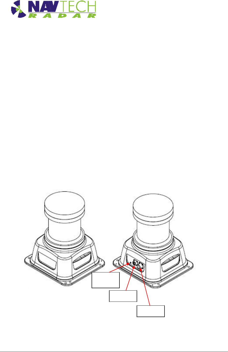
Figure 1 Radar sensor - isometric views
DC power
Ethernet
Pressure
testing plug
Radar Sensor
Installation Guide –TS Series 2-2
Doc ref: MAINT- 0110 Issue 1.2
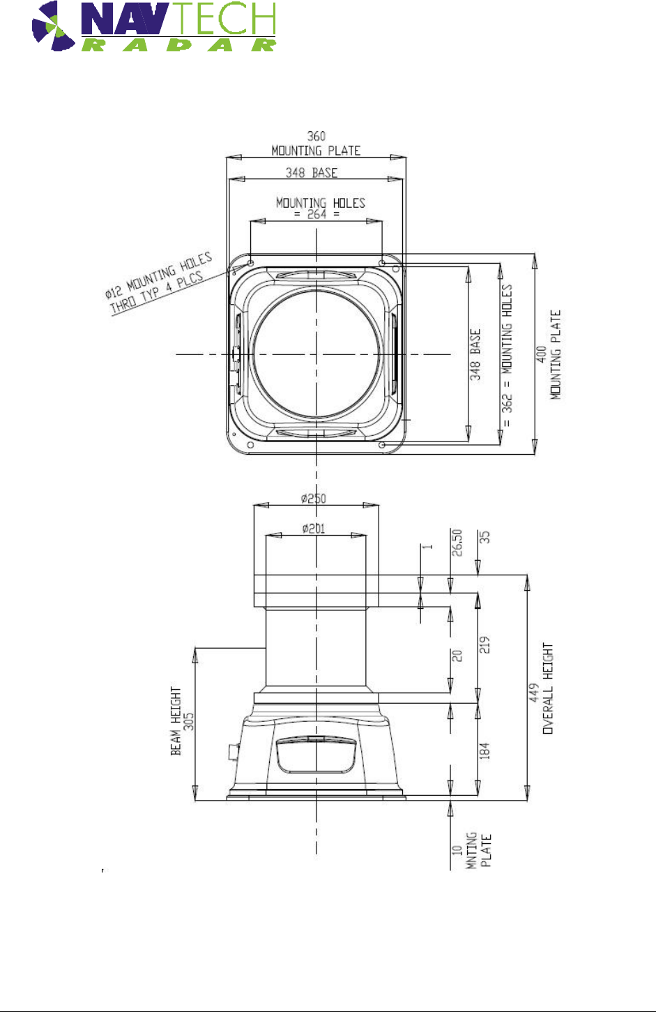
Figure 2 Radar sensor - dimensions
See [D1] for further details on the radar housing.
See the relevant datasheet [6] to [7] for the radar sensor.

Installing the hardware
Installation Guide –TS Series 3-1
Doc ref: MAINT- 0110 Issue 1.2
3. Installing the Radar hardware
3.1 Overview
This section details the installation process, which comprises the following steps:
1. Determine radar sensor locations
2. Mount radar
3. Connect radar sensor
4. Prepare laptop
5. Connect laptop
6. Level radar sensor
7. Install Navtech witness software
8. Confirm sensor coverage
Note: The installation and configuration of the witness software is covered
separately in [2].
CAUTION Before performing any installation task ensure you are aware of Health &
Safety procedures. (See Section 4)
Installing the hardware
Installation Guide –TS Series 3-2
Doc ref: MAINT- 0110 Issue 1.2
3.2 Radar sensor locations
3.2.1 Location
Radar sensors must be positioned to provide the optimum ‘line of sight’. Some guidelines to
check the ‘line of sight’ are given below.
1. As a minimum stand at ground level where the radar is going to be mounted and look in
both directions up and down the road. Whatever you can and cannot see will be the same
for the radar.
2. Ideally you need to have your eyes at the height the radar is going to be mounted. This
may require the use of ladder, podium steps, MEWP (Mobile Elevated Work Platform) /
Cherry Picker / Sky Lift etc. Once your eyes are the same level as the radar, look in both
directions up and down the road. Whatever you can and cannot see will be the same for
the radar.
Be aware of any street furniture (for example, lamp posts) in the radar’s area of coverage.
When looking down a line of lamp posts, the further away they are the closer together
they appear. A line of lamp posts at a certain angle can create a ‘wall’ which neither a
person nor a radar can see through.
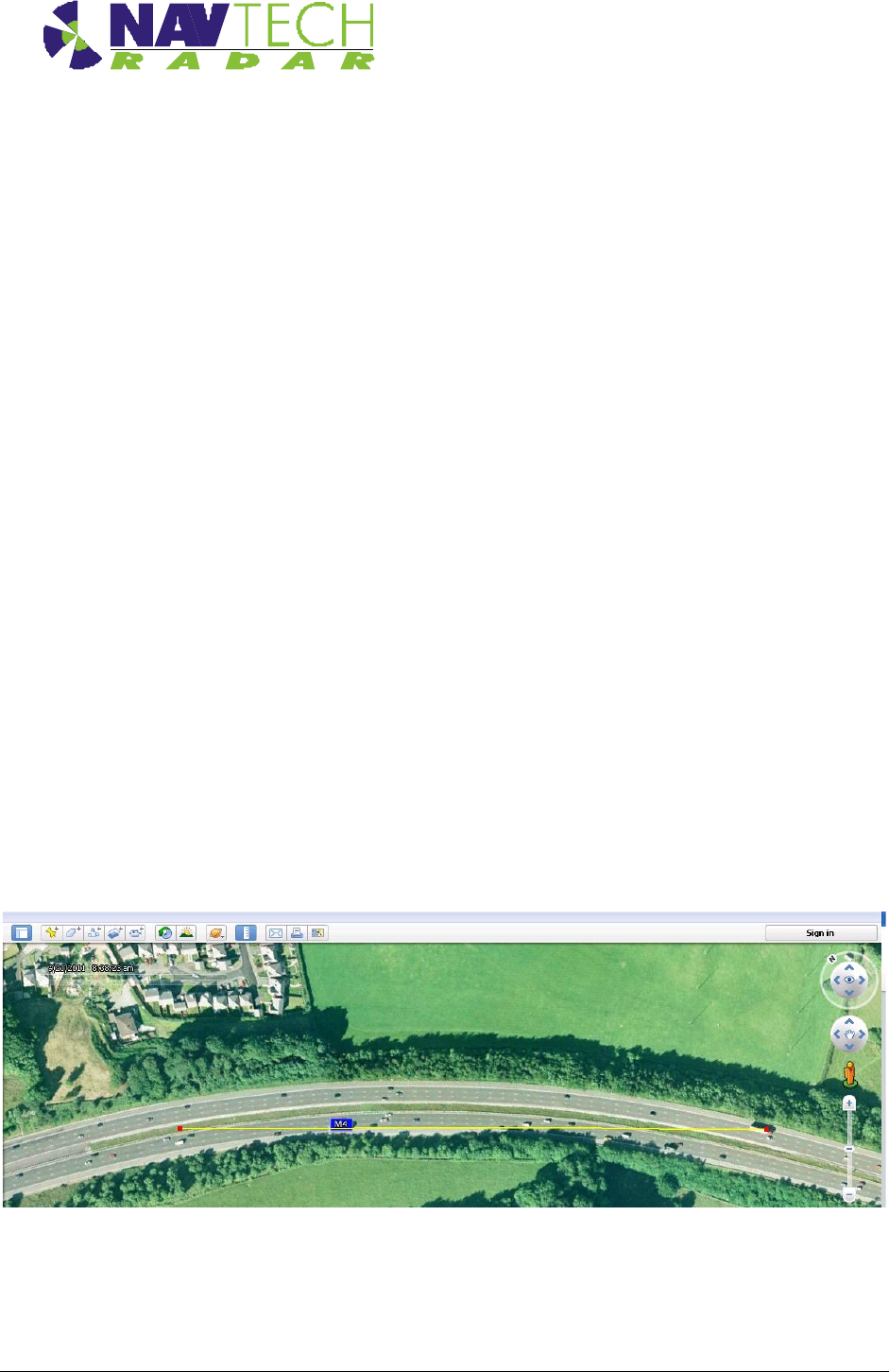
3. To double check the ‘line of sight’ observed from a site visit, use Google Earth and the
ruler tool. (See the yellow line in Figure 3 below). Place one end of the ruler tool where
the radar is going to be located and move the end as if it were the radar beam. If there is
a bend in the road, put the ruler tool on the apex of the corner to see how far the radar
will see.
Figure 3 Google Earth showing line of sight
Installing the hardware
Installation Guide –TS Series 3-3
Doc ref: MAINT- 0110 Issue 1.2
In a straight line the radar can detect a person from 20m away to 350m away. If the person is
closer than 20m they will be below the radar and further than 350m away, they are too small for
the radar to detect. However, if the road curves, the radar cannot detect people, cars, etc. out of
sight around the bend. This must be taken into account when calculating the number of radar
required to provide complete coverage.
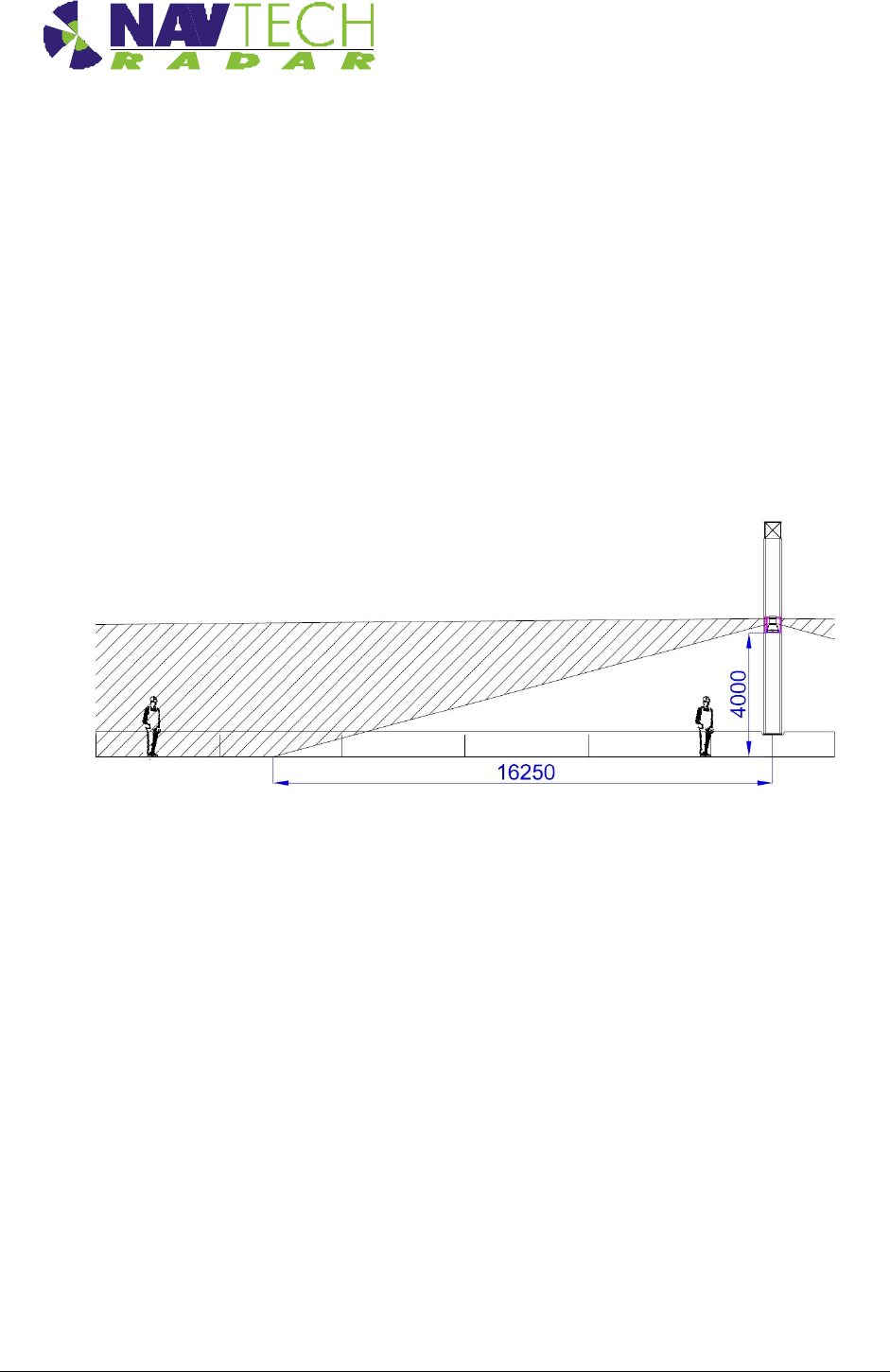
Be aware that for slow or stopped vehicles, a stopped car that ultimately comes to rest directly
beneath the radar will slow down well before this point. The slow vehicle alarm will be raised in
this case. Reducing the radar mounting height can increase coverage close in to the radar. See
[D2]. Figure 4 shows the radar mounted at 4m giving coverage to the ground of
approximately16.25 m.
Figure 4 Radar coverage (mounted at 4 metres)
Refer 3.2.2 for typical installation mounting heights.
Example
Consider the positions of radar sensors used to provide coverage on a road. The position of the
radar is determined by how straight or curved the road is either side of the mounting post/gantry
and what affect the neighbouring street lights may have on the radar’s ‘line of sight’. When you
have a line of street lights on a curve they can have the effect of creating a barrier the radar
cannot see through. Moving the radar from one side to the other side of the central barrier can
have a dramatic effect on improving the radar line of sight. In more extreme cases moving the
radar to the roadside would be required.
In this example, each radar has a possible four locations on, or near, a gantry on the road. See
Figure 5 below.
If the road has a shallow curve, radar Position A or B is selected. If the road has a pronounced
curve, radar Position C is selected - where C is the outside of the curve. If the road is
absolutely straight, the radar is mounted on a post (Position D). Having the radar on a post
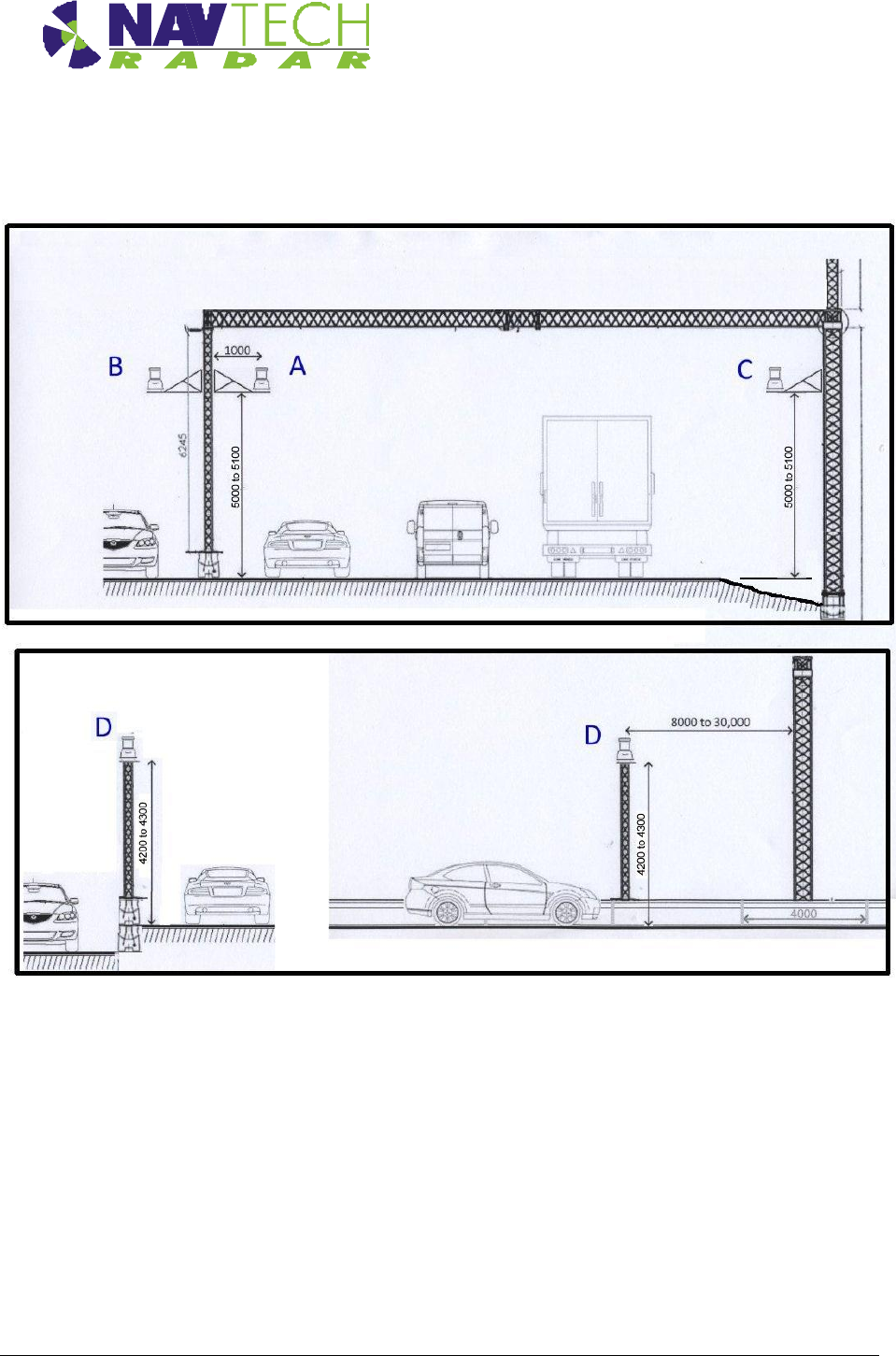
Installing the hardware
Installation Guide –TS Series 3-4
Doc ref: MAINT- 0110 Issue 1.2
located midway between the gantry and the closest street light reduces the occlusion caused by
the both the gantry and the closest street light.
Figure 5 Example radar sensor locations
3.2.2 Mounting height
The sensors can be mounted at various heights between 2m and 8m depending on the
application. Typical installation mounted heights:
For hard shoulder monitoring only – 2m above ground level
Coverage of multiple lanes – 4 to 5 m above road surface
Some site layouts may require the sensor to be mounted at 8m.
Installing the hardware
Installation Guide –TS Series 3-5
Doc ref: MAINT- 0110 Issue 1.2
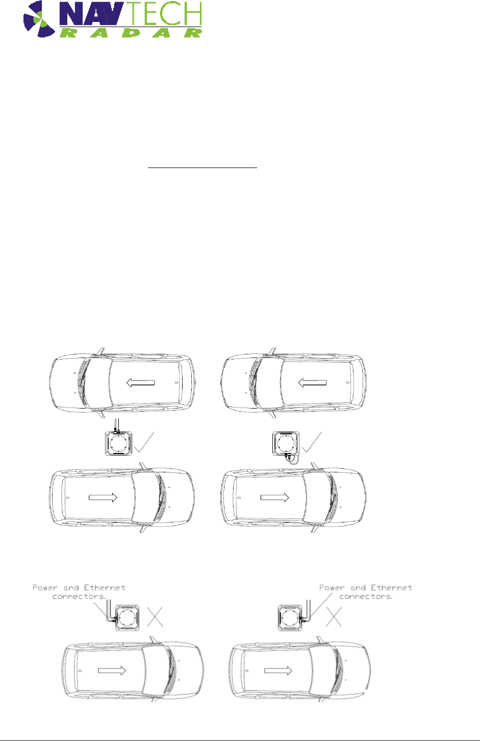
3.2.3 Orientation
When mounting a radar sensor on a road, the orientation is important.
The orientation is the same for mounting the radar at the side of a road or in the centre of the
road. Ensure the side of the sensor with the Serial Number Label, (or the side with the
connectors) is running next to one of the lanes.
Examples
On a road running North to South, the Serial Number Label would point either East or
West.
On a road running East to West, the Serial Number Label would point either North or
South.
Note: Convention would have the Serial Number Label pointing North and the connectors
pointing South. It’s not mandatory though.
Figure 6 Correct orientation of radar
Figure 7 Incorrect orientation of radar
Installing the hardware
Installation Guide –TS Series 3-6
Doc ref: MAINT- 0110 Issue 1.2
3.3 Mounting radar sensor
Radar sensors may be mounted on dedicated posts, or various other structures (e.g walls,
roofs, gantries) using brackets. Sample posts and brackets are shown in Annex B.
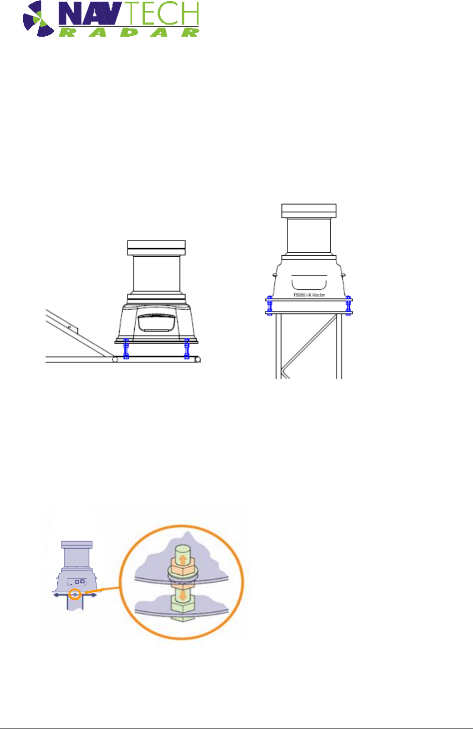
Radar sensors are fitted to a plate on top of the post, or on the bracket, using nuts and bolts,
which allows you to adjust the tilt [See Figure 8 ]. Adjusting the tilt (levelling the sensor) ensures
optimum detection performance and is detailed in Section 3.7.
Figure 8 Mounting plate on post / bracket
The sensor mounting plate (or bracket) design allows for a simple yet effective method to fine
tune the incline of the sensor. For each of the mounting holes, the bolt is fed from underneath
and locked onto the mounting plate with a nut. Two more nuts are used below the radar base
plate and another is used above so that the sensor can be positioned anywhere up or down the
bolt thread, as necessary.
Figure 9 Levelling adjustment
1. Place the radar on the threaded studs of the plate.
Bracket
Post
Installing the hardware
Installation Guide –TS Series 3-7
Doc ref: MAINT- 0110 Issue 1.2
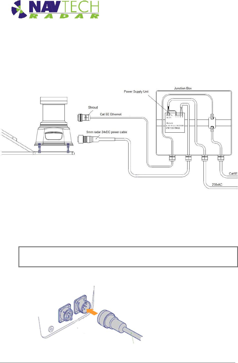
3.4 Connecting radar sensor
Each radar sensor requires a power and a data connection. Both are made using military
specification connectors to ensure link integrity in the harshest environmental conditions. The
power and data connections run from the sensor to a conveniently placed junction box (e.g.at
the base of the post) where the power supply is situated. See Figure 10.
Figure 10 Connections to radar sensor
Supplied with each radar sensor are a power cable with a mil-spec connector for the sensor
connection and a bare end at the junction box connection. A mil spec shroud is also supplied for
use with a suitable environmentally protected Ethernet network connection. It is essential that
the supplied shroud is correctly used to ensure that the data connection is water tight.
IMPORTANT: Failure to correctly fit the shroud can invalidate the warranty on sensors that
have been caused to fail through water ingress.
1. Attach 24vDC connection to the radar.
Figure 11 Connecting radar sensor

Installing the hardware
Installation Guide –TS Series 3-8
Doc ref: MAINT- 0110 Issue 1.2
2. Ensure the Power and Ethernet cables are securely connected into junction box.
3. Ensure the junction box has the Navtech supplied 24vDC power supply installed. (The
power supply unit has a peak current capacity of 4 Amps, though typically the radar
draws a continuous 1 Amp). See.[8].
4. Ensure that the Power supply cabling is correctly terminated at the radar end with a
secure Amphenol MIL spec connector. Pin D (Red or Brown) is 24vDC, Pin J (Blue or
Black) is 0V.
IMPORTANT: To prevent floating voltage levels on the low output of the radar sensor power
supply unit, link the 0v output to earth.
5. Ensure the junction box has an Ethernet cable running to the infrastructure network
switch.
3.5 Preparing the laptop
IMPORTANT: Ensure that your laptop has its IP address set to operate within the same
subnet as the radar sensor
3.5.1 Factory settings
The IP address (e.g. 192.168.0.1) of the radar sensor is preset before leaving Navtech Radar
Limited according to client specifications and will be declared on a label attached to the outer
casing.
The subnet mask of the radar sensor is often preset to 255.255.255.0 but could also be set
wider (such as 255.255.0.0) if requested. Therefore, if the sensor IP address is 192.168.0.1 and
the mask is 255.255.255.0, then your computer must use an IP address in the range:
192.168.0.2 to 192.168.0.254.
3.5.2 Changing factory settings
The IP address and subnet mask can be changed using firmware commands sent to the radar
either via Telnet (see [5]), or using a serial connection (see [D3]).
3.6 Connecting your laptop
1. At the radar, connect the laptop via CAT5 cable to the radar.
2. Ensure that the radar sensor is powered on and is rotating - you can faintly hear the rotor
when it is running.
3. Use SPx Radar View application [1] to display the radar data. (See Annex A )
Installing the hardware
Installation Guide –TS Series 3-9
Doc ref: MAINT- 0110 Issue 1.2
3.7 Levelling radar sensor
3.7.1 Overview
The radar antenna vertical beam is designed to be wide (in range), close in to the radar but it
still narrows to approximately 2 degrees at long range. For optimum detection performance it is
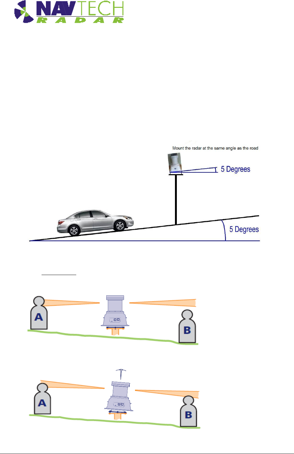
important that each sensor is level in relation to the area that it surveys. Level in this sense may
not mean absolutely horizontal. For instance, if the site has a continual slope it may prove
beneficial to incline the sensor in line with the slope to ensure that the targets are correctly
tracked. See Figure 12.
Figure 12 Levelling a radar sensor
The exaggerated examples below show how a sensor with an incorrect incline could miss
targets which are lower down the slope:
Figure 13 Horizontal radar sensor misses target B
Figure 14 Inclined radar sensor locates both targets
Installing the hardware
Installation Guide –TS Series 3-10
Doc ref: MAINT- 0110 Issue 1.2
3.7.2 Adjusting radar
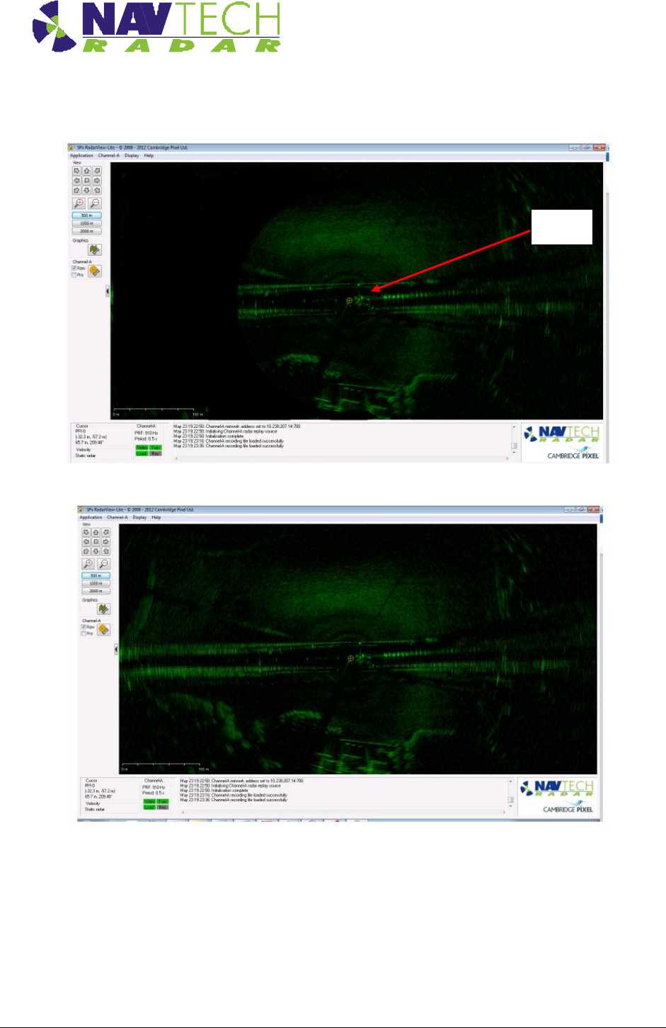
Figure 15 SPx RadarView display (A)
Figure 16 SPx RadarView display (B)
Using the SPx RadarView application to view the radar data (see Annex A), you are aiming to
have an equal amount of data either side of the radar.
1. If there is more radar data one side than the other, as shown in Figure 15, change the
angle of the radar until you have an equal amount of data either side of the radar, as
shown in Figure 16.
Radar
Installing the hardware
Installation Guide –TS Series 3-11
Doc ref: MAINT- 0110 Issue 1.2
2. Watch a vehicle travelling from one side of the radar to the other. Is it dramatically
brighter/giving a stronger return signal from one side to the other? If so, tilt the radar so a
vehicle has equal brightness/signal return strength on both sides of the radar.
3.7.3 Use of Radar Target (Optional)
This test is not possible if working on a live carriageway.
1. Check that the radar is level across the carriageway, then place a radar reflector on a
tripod, in the centre of the carriageway, at 150m along road in each direction, (2 targets in
total).
Note: These two targets must be at the same height (suggested height 1.5 m),
and the area behind the target should be clear for 10-15 m.
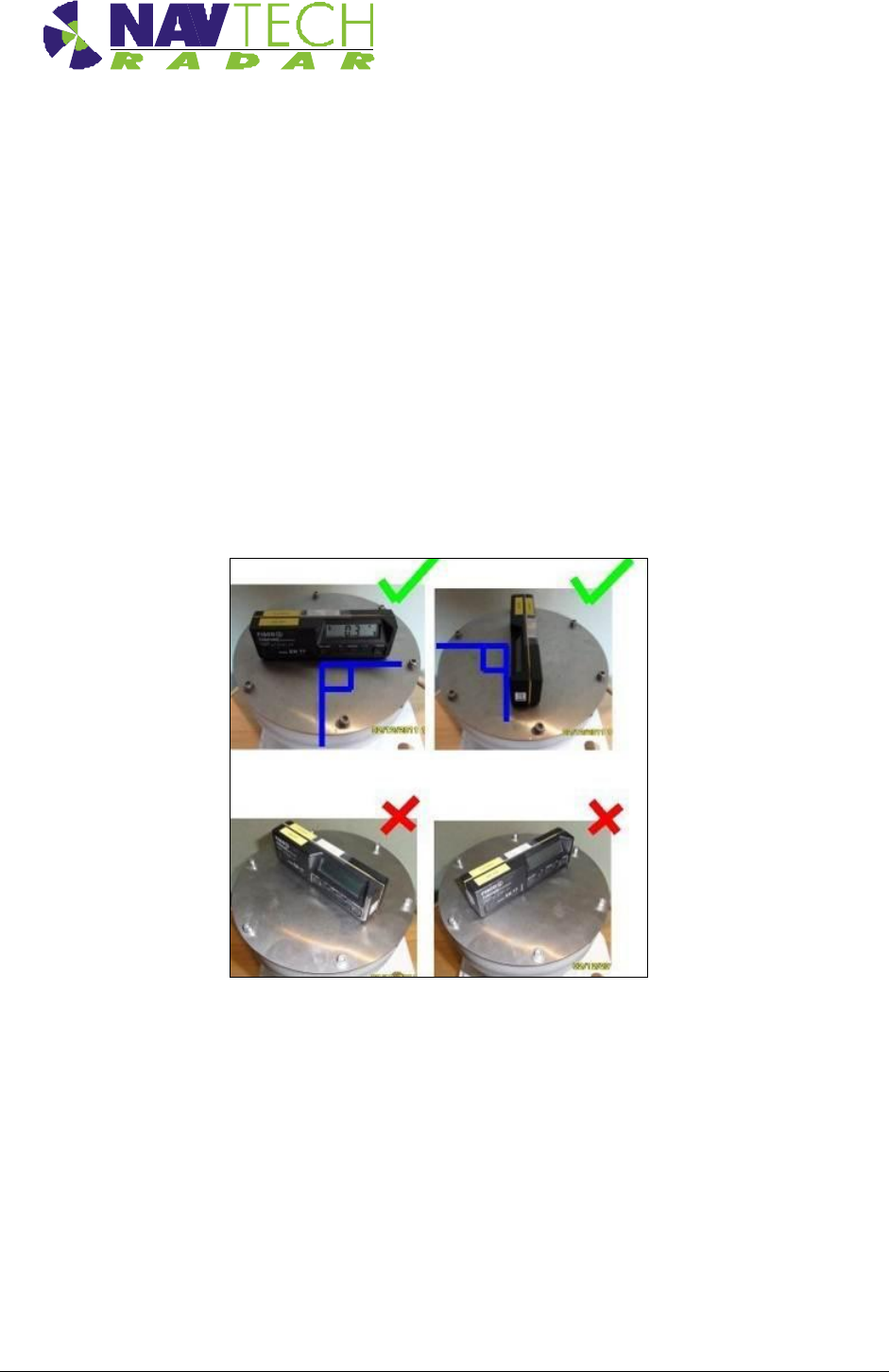
2. Place the Digital Level as indicated in Figure 17, ensuring the level is at right angles to
the base of the radar.
Figure 17 Digital Inclinometer mounted on radar sensor
3. Adjust the radar tilt of the radar on the threaded studs, to maximise the signal level on the
2 targets, using the gradient of the road around the radar as a starting point. Signal levels
are determined from the SPx RadarVew software (See Annex A for detailed instruction).

Installing the hardware
Installation Guide –TS Series 3-12
Doc ref: MAINT- 0110 Issue 1.2
Figure 18 Radar view to locate target
3.8 Securing the radar
1. Secure the radar on the mounting bracket, or post plate. To do this: lock off the two lower
nuts on each stud by tightening one against the other. (This is to ensure that, if the radar
is removed, the tilt angle is not changed)
2. Record the tilt angle from the digital inclinometer. See Annex E for a sample table.
3.9 Confirming sensor coverage
1. Install and configure the witness software as described in [2].
2. Enter basic detection areas into Sentinel. (See [2]).
3. Perform a basic walk through tests of the radar and monitor the tracking performance
along the carriageway, within radar line of site. See [4] for instruction on how to monitor
the performance.
4. Perform a drive through test of this radar. Monitor the tracking performance along the
carriageway, within radar line of site as this test is conducted.

Installing the hardware
Installation Guide –TS Series 3-13
Doc ref: MAINT- 0110 Issue 1.2
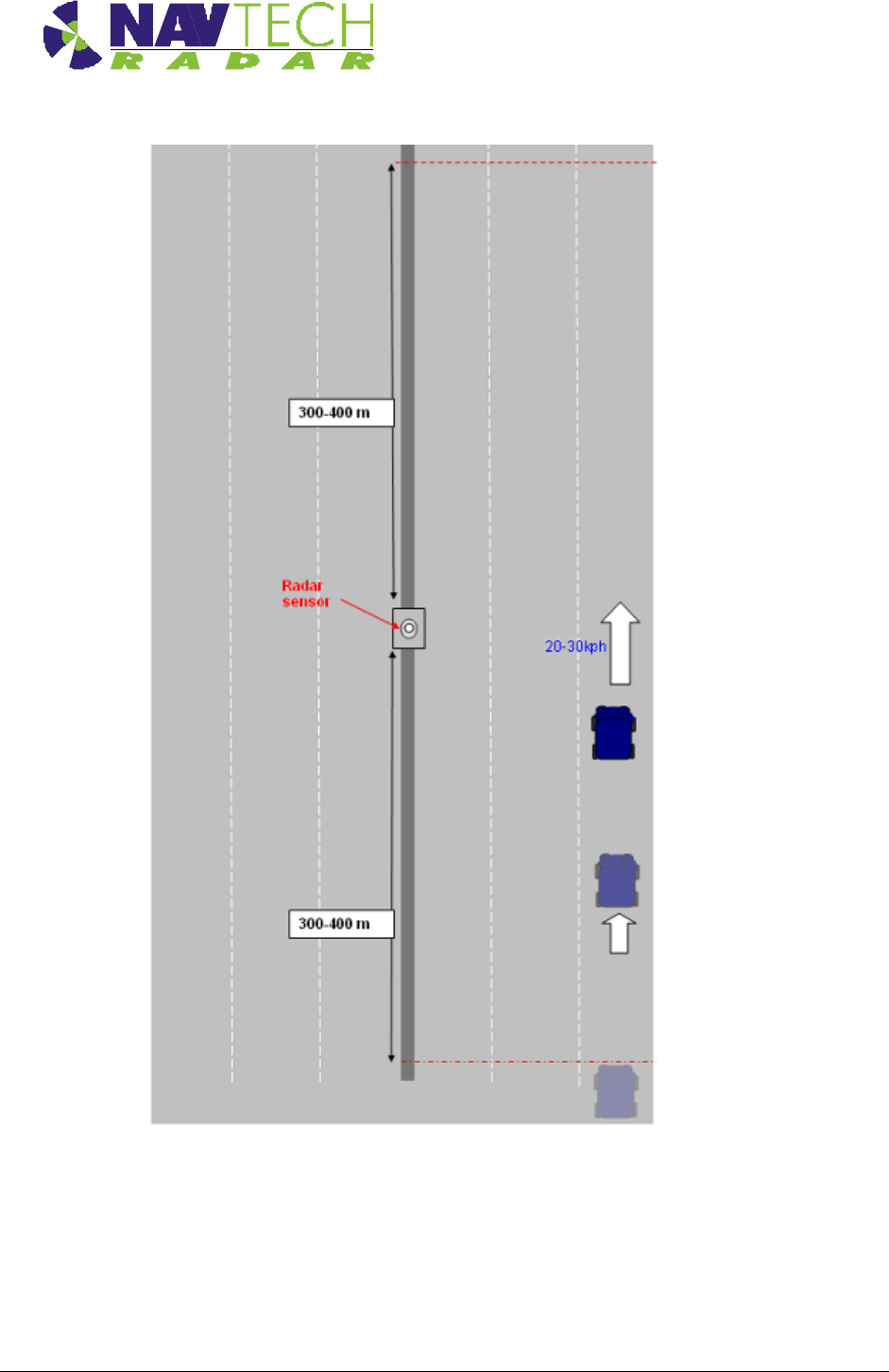
5. During the drive through, record a radar dataset, should further detection zone alteration
be required offline. During this procedure a vehicle should drive at between 20 and 30
kph from the maximum line of sight radar coverage ‘upstream’ of the normal traffic
direction, to the maximum line of sight ‘downstream’ . Typically the overall coverage of a
radar may be from 300 to 400 meters or more upstream, to 300 to 400 meters
downstream. During the drive through the vehicle should stay in the same lane, and the
lane number should be recorded against the dataset for future reference. See Figure 19
on the next page.
6. Refine the radar detection zones, based on the drive and walk through and save the
settings.
7. Disconnect the laptop from the radar and connect the radar to the infrastructure network
switch.
8. Repeat for each radar along the carriageway and verify coverage.
Installing the hardware
Installation Guide –TS Series 3-14
Doc ref: MAINT- 0110 Issue 1.2
Figure 19 Drive through test
Maximum line
of sight
Maximum line
of sight

Health & Safety
Installation Guide –TS Series 4-1
Doc ref: MAINT- 0110 Issue 1.2
4. Health & Safety
4.1.1 General
1. A first aid kit should be available at all times.
2. In addition to the conditions detailed in this section the Site Safety Procedures for the
location where the equipment is being installed must be complied with at all times.
4.1.2 Design
The design and manufacture of all equipment supplied as part of the Navtech radar tracking and
monitoring system for permanent installation is CE accredited:
European Electromagnetic Compatibility Directive 89/336/EEC
ETSI EN301 091-1 Electromagnetic compatibility and Radio Spectrum Matters Short
Range devices
4.1.3 Maintenance
1. Make sure that electrical supplies are properly isolated before removing any covers. The
supply should be disconnected by the operation of the main isolating switch, removal of
fuses or other acceptable method. A notice should be placed at the point of isolation
showing:-
DANGER - WORK IN PROGRESS
2. Place a barrier or guard rail round the work area.
3. When working on elevated equipment, make sure that all ladders and staging are secure.
If necessary, wear a safety harness.
4. Be aware of any special hazards specific to the site or location where equipment is
located. Take all necessary precautions.
Annex A
Installation Guide – I / TS Series A -1
Doc ref: MAINT- 0110 Issue 1.2
Annex A - Using SPx RadarView
The SPx RadarView application consists of two files which must be located in the same folder (any
folder) on your laptop:
SPXRadarView.exe
SPXRadarView.rpi
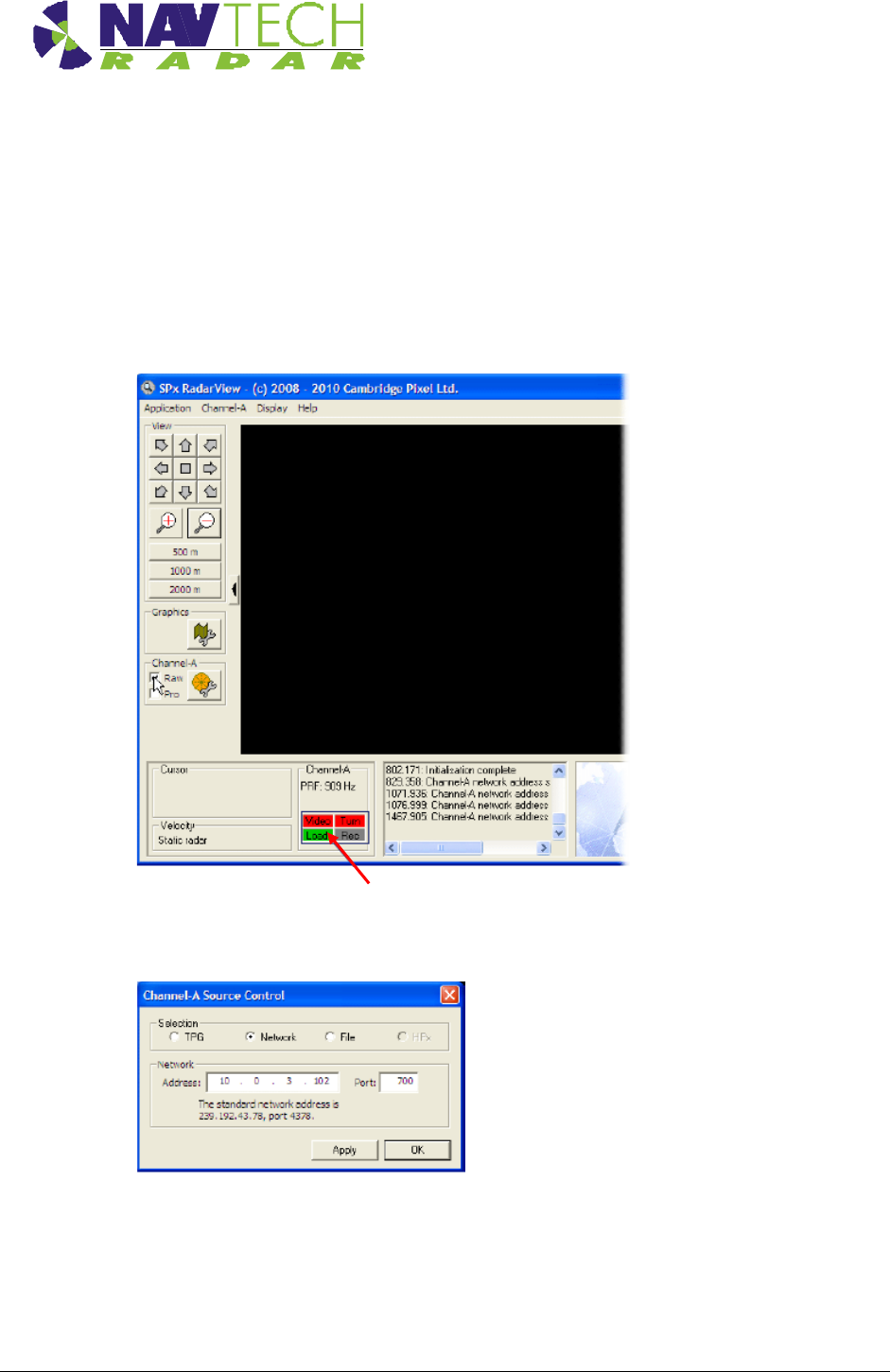
1. Run SPXRadarView.exe. You should see a blank main screen:
Note: In the lower panel, the Video and Turn indicators will be red indicating that
there is no communication with the sensor.
2. Click the Channel-A menu on the toolbar, and select the Source... option.
Ensure that the Selection option is set to Network and in the Address field,
enter the IP Address of the sensor. The Port must be set to 700.
Click OK.
Annex A
Installation Guide – I / TS Series A -2
Doc ref: MAINT- 0110 Issue 1.2
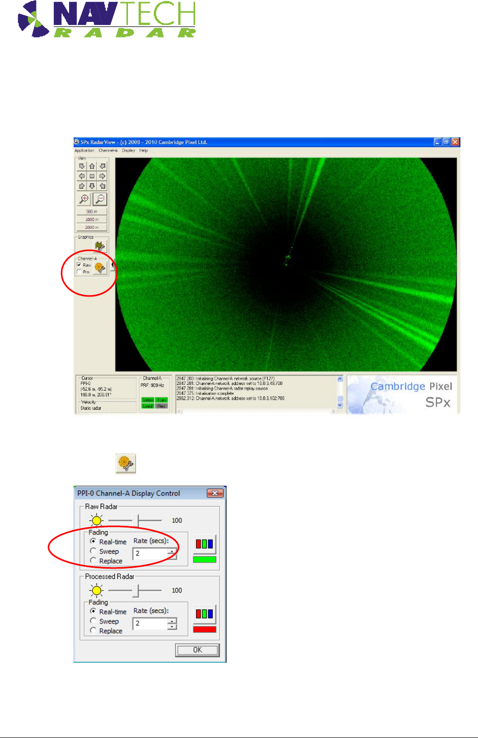
Once the IP address and port are correctly set and the application makes contact with the
sensor, the Video and Turn indicators should turn green. Shortly afterwards, you should
begin to see radar scan information within the main window.
On the left side of the screen, ensure that the Raw option is ticked.
3. Click the button to show the Display Control dialog box:
Ensure that in the Raw Radar section, the Fading option is set to Sweep and the Rate
(sweeps) is set to 5. Click OK.
Annex A
Installation Guide – I / TS Series A -3
Doc ref: MAINT- 0110 Issue 1.2
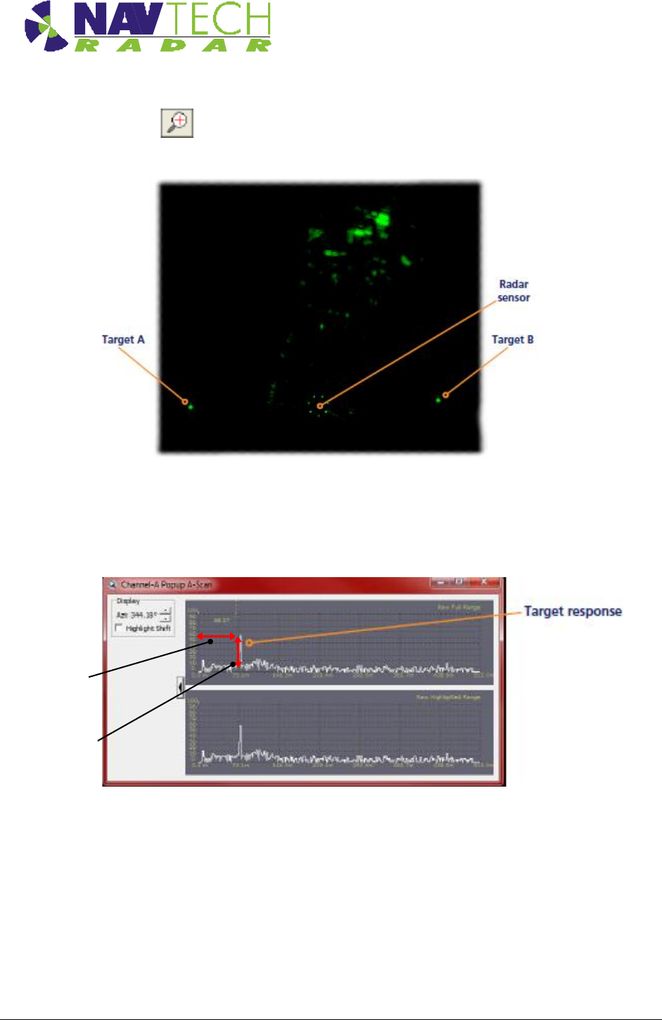
4. Click the button to zoom into the radar view so that you can clearly see the both of
your test targets:
5. Right click the mouse pointer on the exact middle point of one of the targets to display a
popup options box. Click the option Popup Channel-A AScan…. to display a scan
window.
The scan window provides live signal strength data concentrating only on the angular
direction of the chosen target from the radar sensor. In each of the two graph plots, the
x-axis shows the distance from the sensor while the y-axis indicates the returned signal
strength. You should see a spike representing your target at the relevant distance.
Signal strength dB
Distance from
radar m
Annex A
Installation Guide – I / TS Series A -4
Doc ref: MAINT- 0110 Issue 1.2
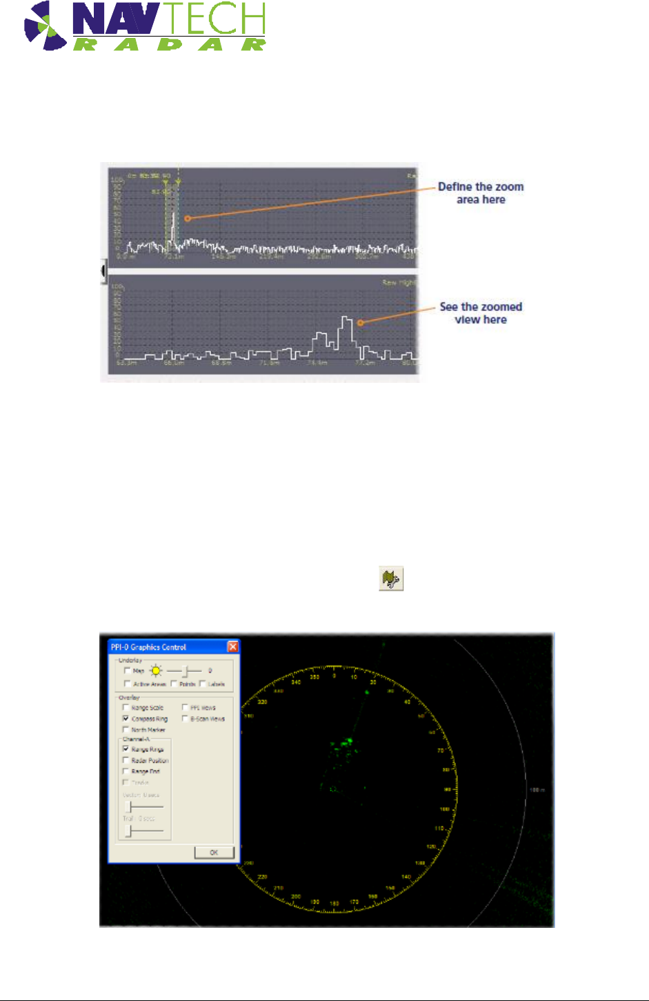
6. On the top graph, left click on either side of the spike to create a zoomed view on the
lower graph.
This will allow you to see small changes in the returned signal strength on the lower
graph when levelling the sensor:
7. Repeat steps 5 and 6 for the other target so that you can view both on screen at the
same time.
8. Adjust the radar sensor level (See Section 3.7) while checking the scan graphs to ensure
the best response from both targets.
9. To assist with orientation, optionally click the button to show the Graphics Control
dialog box:
Two options within this dialog box are of particular use:

Annex A
Installation Guide – I / TS Series A -5
Doc ref: MAINT- 0110 Issue 1.2
- Enable the Compass Ring option to superimpose compass graduation marks
around the sensor view.
Note: North is aligned to the zero point of the radar sensor, not magnetic
north.
- Enable the Range Rings option to overlay range lines every 100m onto the sensor
view
Annex B
Installation Guide – I / TS Series B -1
Doc ref: MAINT- 0110 Issue 1.2
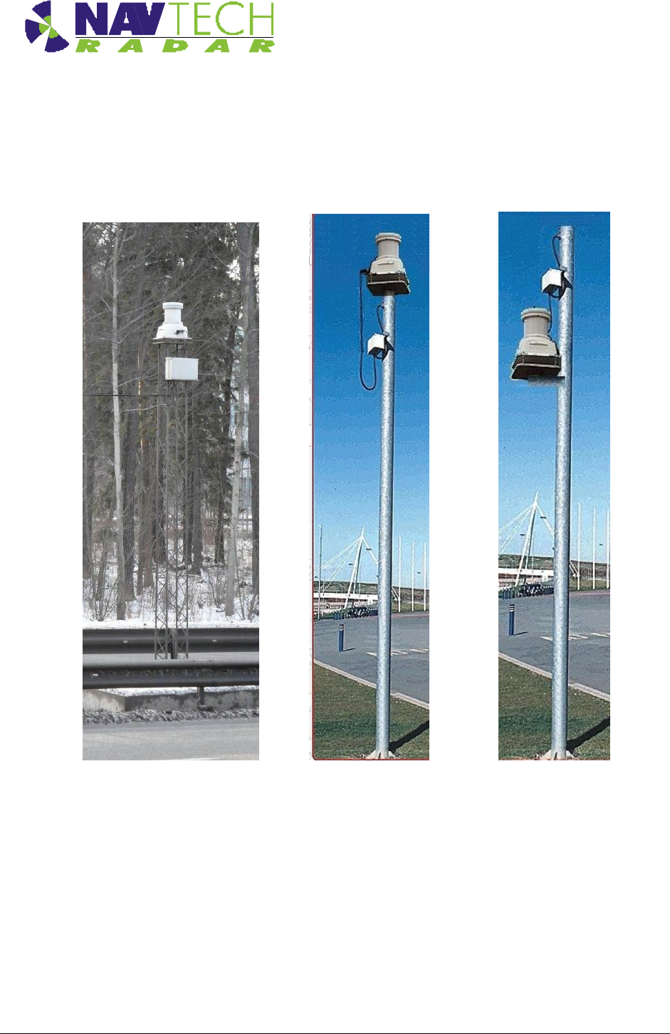
Annex B - Sample Posts and Brackets
B.1 Mounting posts
Examples of mounting posts are shown below:
Figure 20 Radar mounting posts
Annex B
Installation Guide – I / TS Series B -2
Doc ref: MAINT- 0110 Issue 1.2
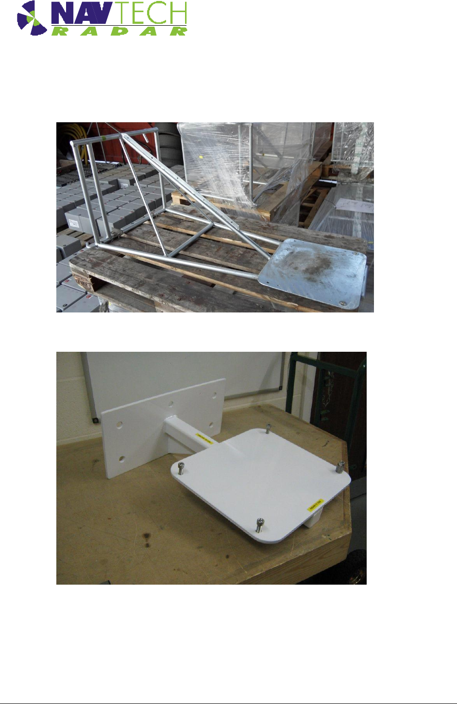
B.2 Mounting brackets
Typical radar sensor mounting brackets:
See [D4] for dimensions.
Figure 21 Mounting brackets
Annex B
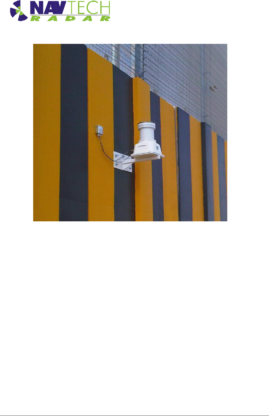
Installation Guide – I / TS Series B -3
Doc ref: MAINT- 0110 Issue 1.2
Figure 22 TS 350-X mounted on a wall

Annex C
Installation Guide – I / TS Series C - 1
Doc ref: MAINT- 0110 Issue 1.2
Annex C - Specifications
This Annex contains the specifications for the cables and connectors supplied by Navtech, with
the exception of the Ethernet connector which is a standard RJ45 connector.

Annex C
Installation Guide – I / TS Series C - 2
Doc ref: MAINT- 0110 Issue 1.2
C.1 Radar power cable
318-B LSZH cable
Part no
Eland A5Z02015BK
No of Cores x Nominal Cross Sectional
Area
2 x 1.5 mm2
Core Identification
2 cores: Blue, Brown
Current carrying capacity
Single phase AC 16 amps
Insulation
LSZH
Sheath
LSZH
Standard
IEC 60092-353
Conductor
Class 5 flexible plain copper to BSN EN 60228:2005
Table 1 Radar power cable specification
C.2 Radar Cat 5E cable
Cat 5E cable
Part no
Eland A8NCAT5EFTPGSWB
No of pairs
4
Core Identification
4 pairs: Blue + White/Blue, Orange + White/Orange, Green +
White/Green, Brown + White/Brown
Standards
ISO/IEC 11801, TIA/EIA 568B
Braiding
GSWB (Galvanised Steel Wire Braid)
Sheath
LSZH
Sheath colour
Black
Table 2 Radar Cat 5E Ethernet cable specification
C.3 Radar power cable connector (radar end)
Amphenol 97 series
MIL Spec
MIL-C-50152
Model
3106A
Operating temperatures
–55°C to +125°C
Power pins
Pin D (Red or Brown wire) & Pin J (Blue or Black wire)
Design Characteristics
10 socket plug
Single key/keyway polarization
Threaded coupling, hard dielectric inserts
Table 3 Radar power cable (radar end) connector specification

Annex C
Installation Guide – I / TS Series C - 3
Doc ref: MAINT- 0110 Issue 1.2
C.4 Radar Cat 5E cable connector (radar end)
Amphenol RJF series
Part No
RJF6
MIL Spec
MIL-C-26482
Data Transmission
Category 5e per ISO/IEC 11801
Mechanical
Bayonet coupling (Audible & Visual coupling signal)
4 mechanical Coding / Polarization possibilities by the user (insert
rotation)
RJ45 cordset retention in the plug : 100 N in the axis
Mating cycles : 500 min
Environmental Protection
Sealing: IP67
Salt Spray : 48 h with Nickel plating> 96 h with black coating> 500 h
with hard anodic coating and Cadmium
Fire /Low Smoke: UL94 V0 and NF F 16 101 & 16 102
Vibrations : 25 –250 Hz, 5 g, 3 axes : no discontinuity> 1μs
Humidity: 21 days, 43°C, 98%humidity
Rapid change of Temperature: 5 –20°C / +85°C cycles
Table 4 Radar Cat 5E cable connector (radar end) specification
Annex D
Installation Guide – I / TS Series D - 1
Doc ref: MAINT- 0110 Issue 1.2
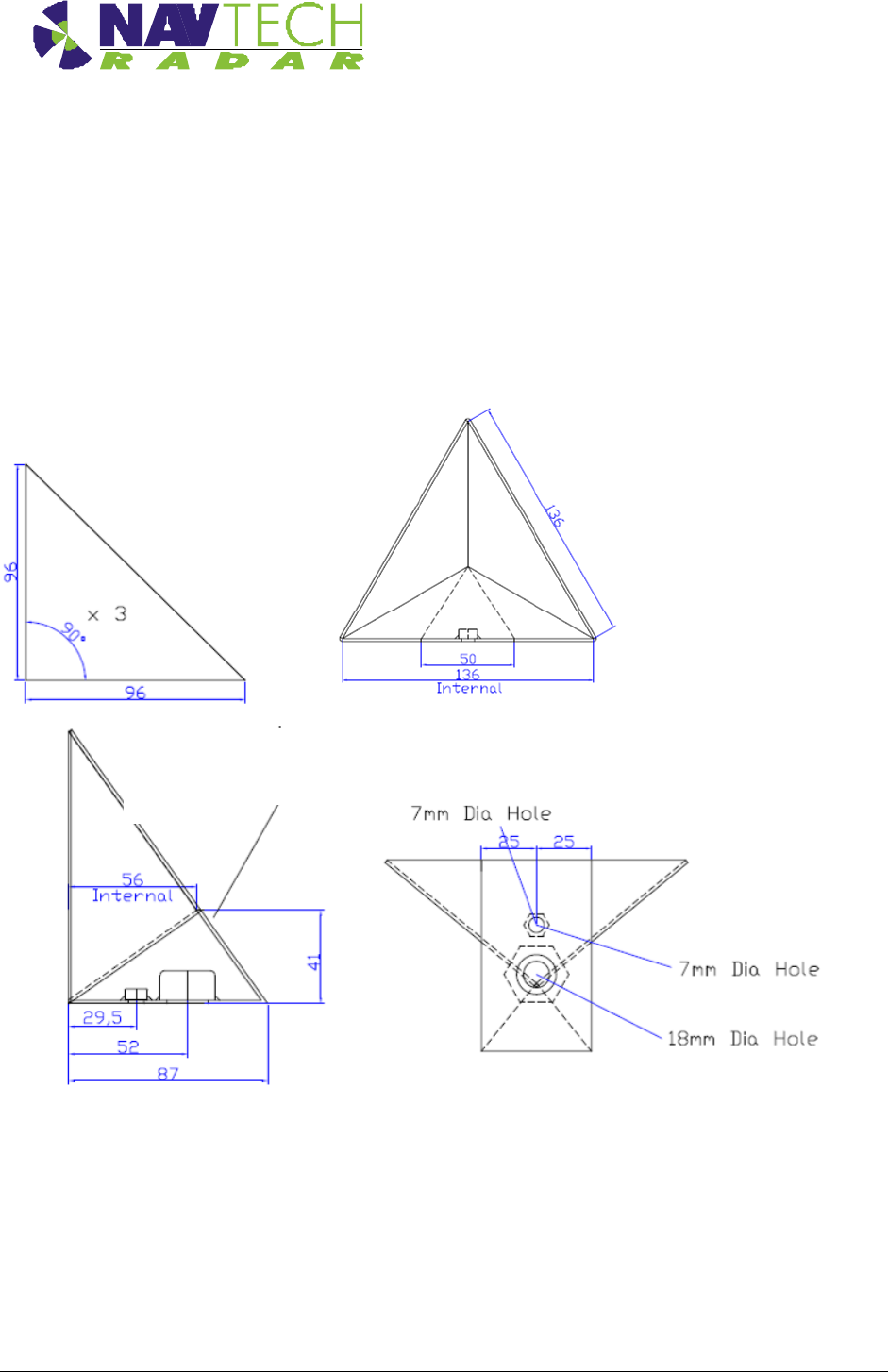
Annex D - Construction of test target
The following drawings show how to construct a test target.
Tolerancing: +/- 1mm on linear dimensions
Material: 1.5 stainless
Finish: Bare metal
The target can be made by welding 3 flat triangles together, or by folding one piece and welding the
meeting edges:
The lower piece can overlap on to the back of
the target to ease production and increase
strength
Back of
target
Welded on ¼ Whitworth and 5/8th UNC
stainless nuts

Annex E
Installation Guide – I / TS Series E - 1
Doc ref: MAINT- 0110 Issue 1.2
Annex E - Radar sensor configurations
A sample table to record data for each radar.
Radar
Sensor
Serial
No
IP Address
Subnet Mask
Geographical position
Lat(N) Long (E)
Radar Base
Plate Angle
(deg)
Example
100
192.168.1.170
255.255.255.0
59.25023
17.85109
+1.5
A1
A2
A3
A4

Annex F
Installation Guide – I / TS Series F- 1
Doc ref: MAINT- 0110 Issue 1.2
ANNEX – F Radio Frequency Energy Compliance
FCC compliance statement (United States)
This device complies with Part 15 of the FCC Rules. Operation is subject to the following two conditions:
(1) This device may not cause harmful interference, and
(2) This device must accept any interference received, including interference that may cause
undesired operation.
The operation of this device is limited to a fixed position at airport locations for foreign object debris
detection on runways and for monitoring aircraft as well as service vehicles on taxiways and other airport
vehicle service areas that have no public vehicle access. This equipment must be mounted in a fixed
location maintaining a minimum separation distance of 40cm from personnel when in general
operation. This restriction of operation is specific for use in North America. For use in other regions
aligned to the FCC regulations, specific country restrictions should be reviewed.
Changes or modifications not expressly approved by the party responsible for compliance could void the
user’s authority to operate the equipment.