Navtech Radar TS350X-001 TS350-X Position Sensing Radar User Manual User Guide 2
Navtech Radar Ltd TS350-X Position Sensing Radar User Guide 2
Contents
- 1. User Guide 1
- 2. User Guide 2
User Guide 2


Document History
Installation Guide –I Series i
Doc ref: MAINT- 0111 Issue 1.2
Document History
Issue
Date
Description
1.0
19/09/2012
First Draft
1.1
14/03/2013
Update for FCC statement
1.2
20/03/2013
Updated the FCC statement

Contents
Installation Guide –I Series ii
Doc ref: MAINT- 0111 Issue 1.2
1. Introduction 1-1
1.1 Scope 1-1
1.2 Essential Items 1-1
1.3 Pre requisites to working on a Container Crane & Bulk Loaders 1-2
1.4 Radar sensor 1-1
2. Installing the Radar hardware 2-3
2.1 Overview 2-3
2.2 Radar sensor locations 2-4
2.2.1 Location 2-4
2.2.2 Orientation 2-9
2.3 Mounting radar sensor 2-10
2.4 Connecting radar sensor 2-11
2.5 Preparing the laptop 2-13
2.5.1 Factory settings 2-13
2.5.2 Changing factory settings 2-13
2.6 Connecting your laptop 2-13
2.7 Levelling radar sensor 2-13
2.7.1 Adjusting radar 2-15
2.8 Securing the radar 2-16
2.9 Confirming sensor coverage 2-16
3. Health & Safety 3-17
3.1.1 General 3-17
3.1.2 Design 3-17
3.1.3 Maintenance 3-17
Annex A Using SPx RadarView 1
Annex B Sample Brackets 1
Annex C Specifications 1
C.1 Radar power cable 1
C.2 Radar Cat 5E cable 1
C.3 Radar power cable connector (radar end) 1
C.4 Radar Cat 5E cable connector (radar end) 3
Annex D Construction of test target 1
Annex E Radar sensor configurations 2

Contents
Installation Guide –I Series iii
Doc ref: MAINT- 0111 Issue 1.2
List of figures
Figure 1 Radar sensor - isometric views ....................................................................................... 1-1
Figure 2 Radar sensor - dimensions .............................................................................................. 1-2
Figure 3 Single radar mounted on the underside of a bulk loader ................................................. 2-4
Figure 4 A single radar detects objects as the boom luffs ............................................................. 2-5
Figure 5 Detection on either side of a boom with a moveable loading chute, with 2 radar ........... 2-6
Figure 6 This loader is shown with combined horizontal and vertical scanning radar ................... 2-7
Figure 7 The scan plane of vertically scanning radar sensors ....................................................... 2-8
Figure 8 Single Radar on an STS, container handling crane......................................................... 2-9
Figure 9 Plan view of a radar, showing the encoder zero angle .................................................. 2-10
Figure 10 Mounting radar on posts/brackets, for both vertical and horizontally scanning radar ... 2-10
Figure 11 Levelling adjustment ...................................................................................................... 2-11
Figure 12 Connections to radar sensor .......................................................................................... 2-11
Figure 13 Connecting radar sensor ................................................................................................ 2-12
Figure 14 Horizontal radar sensor misses target B ........................................................................ 2-14
Figure 15 Inclined radar sensor locates both targets ..................................................................... 2-14
Figure 16 Digital Inclinometer mounted on radar sensor ............................................................... 2-14
Figure 17 SPx RadarView display (A) ............................................................................................ 2-15
Figure 18 SPx RadarView display (B) ............................................................................................ 2-15
Figure 19 Radar view to locate target ............................................................................................ 2-16
Figure 20 I-200 mounted on a ship to shore container crane. ............................................................. 1
Figure 21 Mounting bracket, and installed on a wall ............................................................................ 1
Figure 22 Two possible methods of mounting a radar centrally, under the boom ............................... 3
List of tables
Table 1 Calculating the installation distance of radar from boom ................................................. 2-6
Table 2 Radar power cable specification .......................................................................................... 1
Table 3 Radar Cat 5E Ethernet cable specification .......................................................................... 1
Table 4 Radar power cable (radar end) connector specification ...................................................... 1
Table 5 Radar Cat 5E cable connector (radar end) specification ..................................................... 3

Referenced Documents
Installation Guide –I Series iv
Doc ref: MAINT- 0111 Issue 1.2
Referenced Documents
Ref
Title
Supplier
Doc Ref No
1
RadarView-Lite for Windows User
Manual
Cambridge
Pixel
CP-25-127-03
2
SafeGuard witness Commissioning
Guide
Navtech
3
Navtech Service & Maintenance
Manual I-TS Series Radar
Navtech
MAINT 0010
4
SafeGuard witness Operating Guide
Navtech
5
Entry and User Level Firmware
Commands for all W, I and AGS
Series
Navtech
RND – S0069
6
I 200 Datasheet
Navtech
7
Power Supply unit datasheet
Siemens
https://support.automation.siemens.com
6EP1332-1SH52 Data sheet
8
Local Processing Unit Datasheet
Navtech
ANC-0015
9
6 Channel Relay Module
Navtech
ANC-0024
10
Radar power cable assembly
Navtech
SUB-0022
Drawings List
Ref
Drawing No
Title
D1
ASM 0031
Radar Housing
D2
SUB 0119
Inline Power and Serial Cable
D3
MBP 0260
Steel bracket

Introduction
Installation Guide –I Series 1-1
Doc ref: MAINT- 0111 Issue 1.2
1. Introduction
1.1 Scope
The Navtech SafeGuard Detection system provides an automatic monitoring solution for open
areas such as airports, outdoor industrial machines and vehicles that commonly operate in
ports, mines or other industrial areas. The SafeGuard system comprises a high frequency radar
sensor, linked to a software system, witness. This guide provides instruction for the radar
sensor installation ONLY. The installation of the witness application is covered separately in [2].
Service and Maintenance procedures are also covered separately in [3].
The instructions in this guide are applicable to the following Navtech radar sensors:
I 200
I 500
Details are provided for all the hardware components required for the installation.
1.2 Essential Items
The following are essential additional items that you need to install a radar sensor:
(i) Electrical Power
Electrical power (110 to 230vAC) sourced from, for example, local mains.
110 to 230vAC power is required for the Radar’s 24vDC PSU.
- 110 to 230vAC power is also required for the Laptop Computer used during the
commissioning process.
Note: Radars are network intensive. Some laptops reduce the performance of their
network connection when only running on their internal battery.
(ii) A way of working safely at height
Most Container Cranes and Bulks Loader have walkways with hand rails - keeping to within the
confines of these hand rails, will keep you relatively safe. However this does depend on the
specific machine or site you are working on. If required to do wear a harness and fall arrestor –
Make sure you clip on to a secure structure or on to a dedicated cable/SWR rope.
Make sure any equipment used conforms to:
Shock Absorbing Lanyards – EN354/355
Harnesses – EN361/prEN1496/1497/1498/020895
Retractable Type Fall Arrester - EN360

Introduction
Installation Guide –I Series 1-2
Doc ref: MAINT- 0111 Issue 1.2
(iii) Laptop computer
The laptop should have:
- RJ45 Ethernet connection.
- 9 pin Com port or USB to RS232 adapter [Optional]
- Software – SPxRadarViewLite-V1.47.1 or higher
- Serial communication software – e.g. HyperTerminal, TeraTerm, Putty.
(iv) Cat5E shielded patch lead (or Cross over cable, if laptop doesn’t have Auto-MDIX)
(v) M10 nuts and bolts for mounting radar
The minimum for one radar, in A4 Stainless Steel.
- x4 off M10x80 HEX Set Screw
- x4 off M10 spring washers
- x4 off M10 plain washers
- x4 off Nyloc Nuts
- x12 off M10 Full plain nuts
- x2 off 17mm Spanner for the M10 nuts and bolts above.
(vi) 5m tape measure
(vii) Digital Level
1
(viii) 25m² Trihedral Radar Target
(ix) Pair of 2 way radios
(x) An assistant
(xi) Power Supply cable (Minimum Requirement) - see 0Table 2 for specification, or Inline
Radar Power, Serial and Current Cable (Optional) - see [3].
1.3 Pre requisites to working on a Container Crane & Bulk Loaders
Follow local Health and Safety guidelines, as determined by local safety management
procedures. Navtech training courses are available, offering practical advice and
recommendations on how to successfully install and commission the SafeGuard products
1
Recommended Fisco Solatronic EN17
Health & Safety
Installation Guide –I Series 1-1
Doc ref: MAINT- 0111 Issue 1.2
1.4 Radar sensor
The Navtech radar sensor will detect both small and large objects, moving or stationary, within
its line of sight. It is designed to cover 360 degrees, and samples data at an angular resolution
of approximately 0.4 degrees. The radar antenna is designed to have a narrow beamwidth in
azimuth and elevation – typically 1.8 degrees; in this way objects within the radar field of view
can be accurately located on the road surface.
The standard update rate for radar sensors is 120 rpm with a maximum detection distance of
200 meters radius. A signal return is produced and sent to the processing system every 0.25
meters from the sensor itself up to the maximum sensor range of 200 meters radius. This is
repeated at each new azimuth angle as the antenna rotates. The system employs a frequency
modulated sensor and so unlike Doppler systems, no movement is necessary to measure a
vehicle, person or similar object within the radar line of sight.
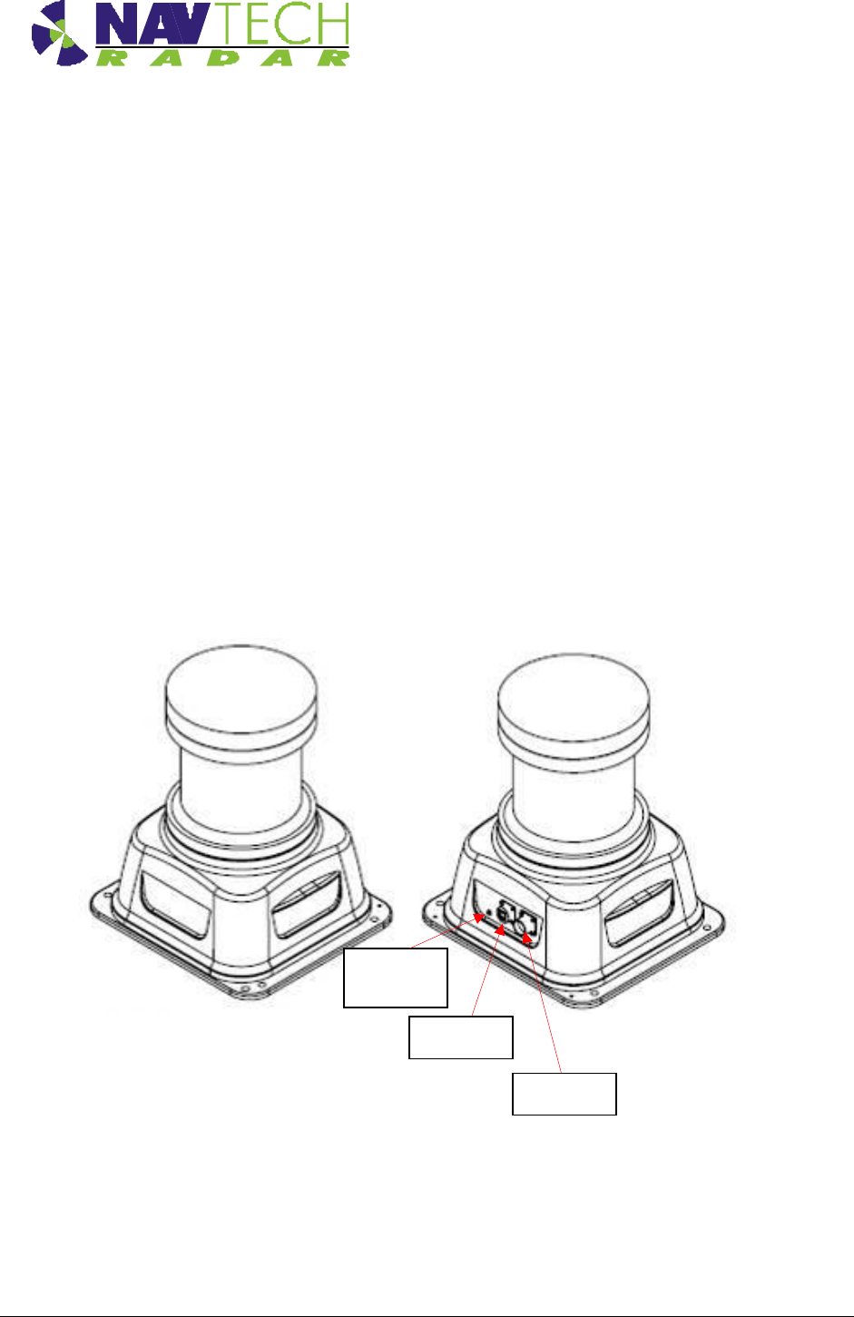
Figure 1 Radar sensor - isometric views
DC power
Ethernet
Pressure
testing plug
Health & Safety
Installation Guide –I Series 1-2
Doc ref: MAINT- 0111 Issue 1.2
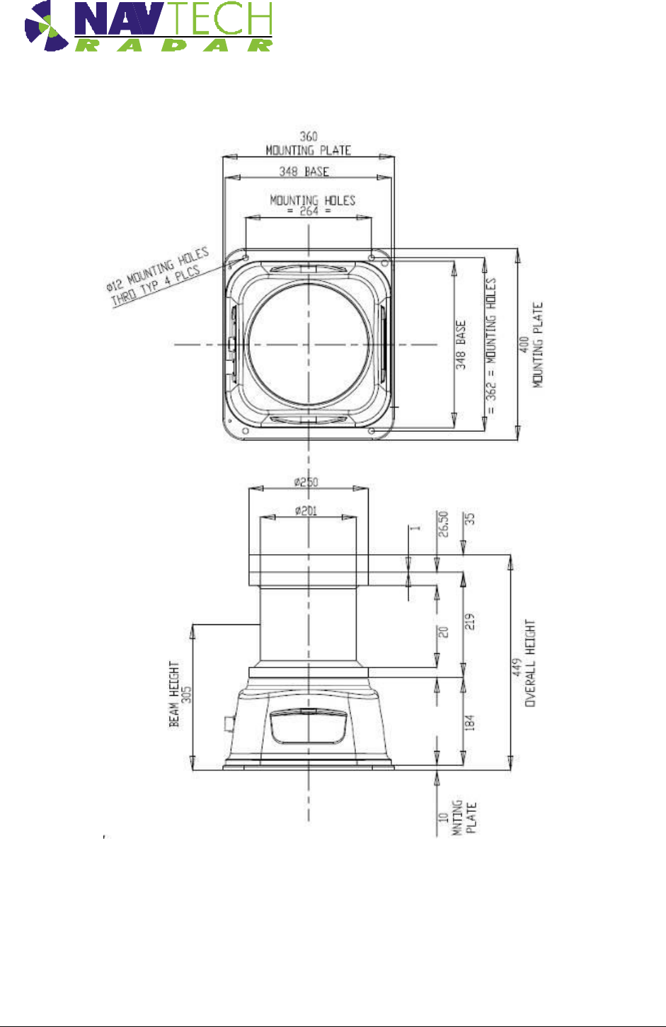
Figure 2 Radar sensor - dimensions
See [D1] for further details on the radar housing. Each radar is supplied with a Power cable
assembly[10] and an Ethernet environmental shell (which fits over a standard RJ45 to provide
an IP67 seal). Further connector detail in Annex C

Health & Safety
Installation Guide –I Series 2-3
Doc ref: MAINT- 0111 Issue 1.2
2. Installing the Radar hardware
2.1 Overview
This section details the installation process, which comprises the following steps:
1. Determine radar sensor locations
2. Mount radar
3. Connect radar sensor
4. Prepare laptop
5. Connect laptop
6. Level radar sensor
7. Install Navtech witness software
8. Confirm sensor coverage
Note: The installation and configuration of the witness software is covered
separately in [2].
CAUTION Before performing any installation task ensure you are aware of Health &
Safety procedures. (See Section 0)
Health & Safety
Installation Guide –I Series 2-4
Doc ref: MAINT- 0111 Issue 1.2
2.2 Radar sensor locations
2.2.1 Location
Radar sensors must be positioned in such a location that they have optimum ‘line of sight’. To
the objects they are to detect. Both I-200 and I-500 radar sensors scan in a horizontal beam.
The witness processing software is designed to generate an alarm signal, should an object
appear within a detection zone, software configured to lie within the scan area. Other factors to
consider when choosing a mounting location include how close the radar is to a power source
on the machine. Also accessibility, both for installation and on-going maintenance.
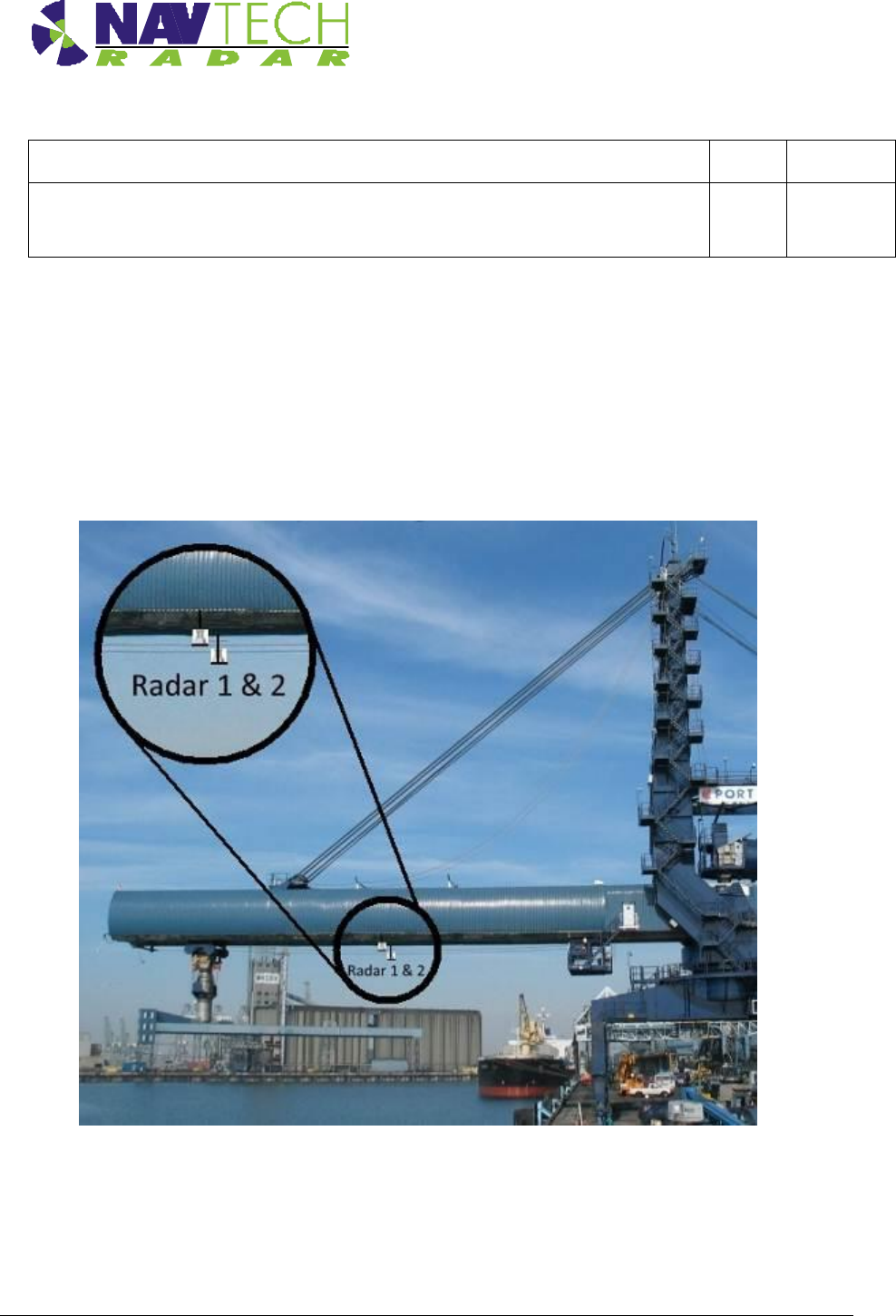
Example 1 – Radar installed centrally on the underside of a boom
Below are two diagrams of a radar centrally mounted on the underside of a bulk loader boom.
This mounting location is only suitable if there is no trolley, or loading chute that travels along
the underside of the boom. In this case the installed radar would obstruct the free movement of
the chute
The reason for placing a radar in this location is to detect objects to the side of the boom, which
could be struck if the bulk loaded slewed or long travelled in that direction. A single radar offers
protection on both side of the boom
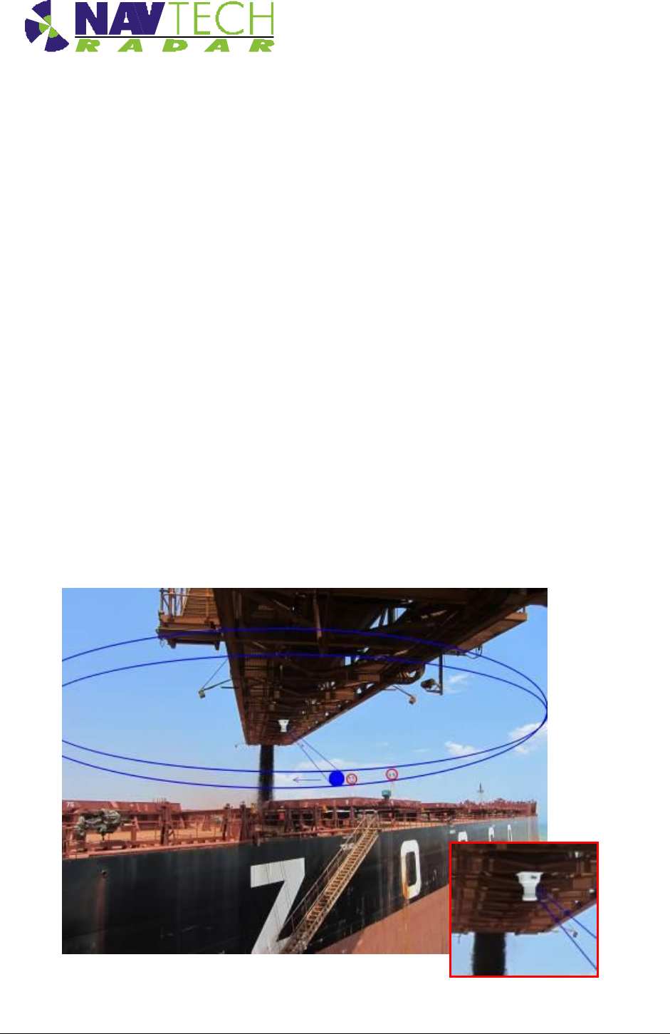
Figure 3 Single radar mounted on the underside of a bulk loader
Health & Safety
Installation Guide –I Series 2-5
Doc ref: MAINT- 0111 Issue 1.2
The primary use of the single radar scanning a horizontal plane is to protect slew and long travel. A
secondary benefit though, is to stop the boom being lowered/luffed down on to an object that is
raised above the deck level of a vessel. Although, this radar will not detect objects that are beneath
the pane of the horizontal scan, as the boom luffs down these objects should be detected. Care
should be taken to ensure the radar is mounted at a sufficient distance from the underside of the
boom, so the luff motion can be stopped in time to prevent a collision.
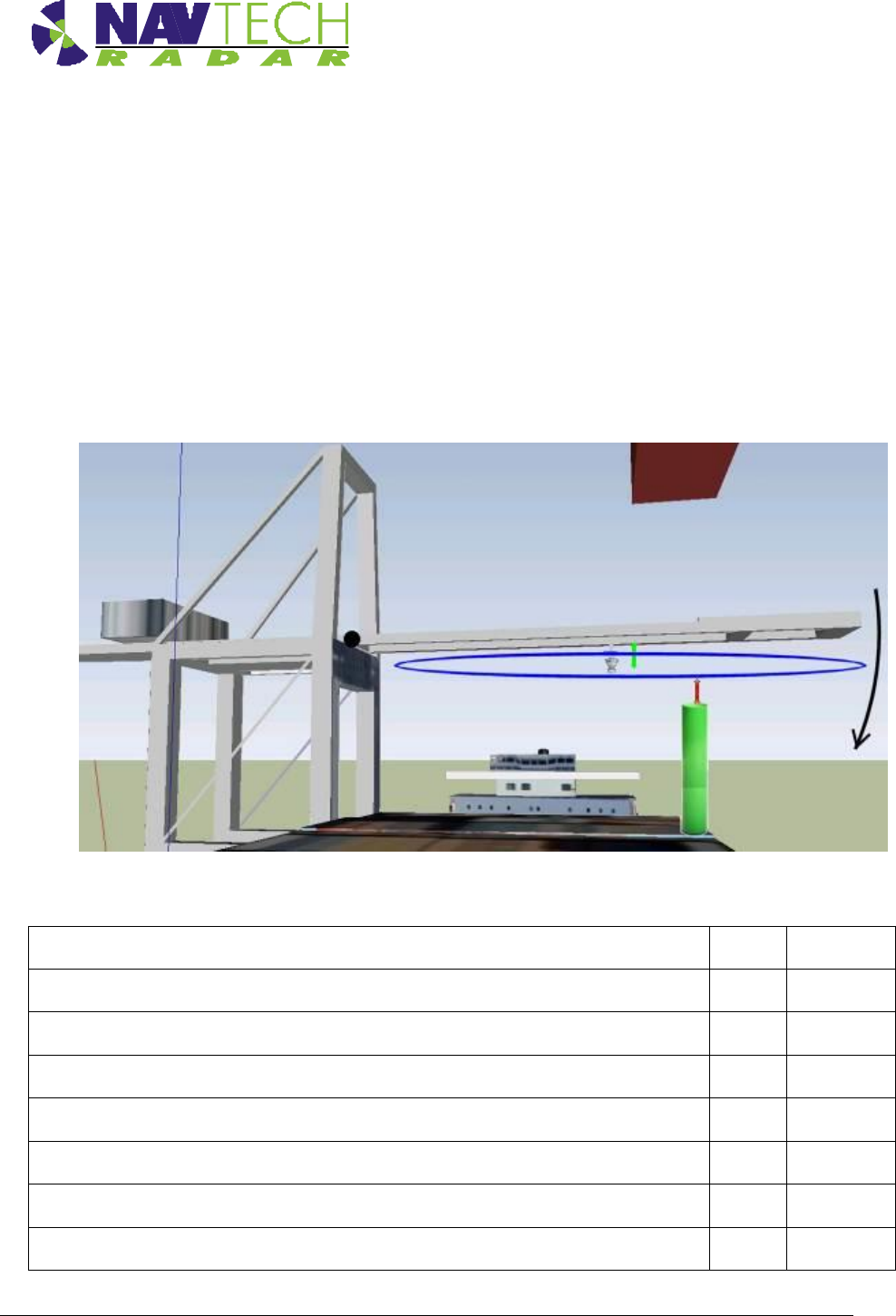
By considering the rate of luff of the boom; the scan rate of the radar (typically 2 rps); and the
number of required detections configured in the witness processing software to generate a stop
alarm; the ideal separation between radar and boom can be calculated.
Figure 4 A single radar detects objects as the boom luffs
Luff Operation - Vertical Radar
Boom length
52
meters
rate of turn on boom Luff
0.15
deg/sec
velocity at the tip of the boom
0.14
meters/sec
Radar detections configured in software processing, to raise a stop alarm
4
Time to detect, for a 2 Hz radar [4Hz option available]
2.0
Sec
Luff meters moved at the boom tip, before full detection
0.27
meters
Safety Margin, to accommodates the boom stopping distance
1.5
meters
Health & Safety
Installation Guide –I Series 2-6
Doc ref: MAINT- 0111 Issue 1.2
Configured Min working distance Vertical
1.77
meters
Expected radar mounting distance, offset from the boom (note the beam to
mounting base distance is approx. 300mm)
1.47
meters
Table 1 Calculating the installation distance of radar from boom
to detect a raised spar whilst the boom Luffs
Example 2 – Radar installed on each side, on the underside of a boom
The example below shows how two can be used to detect on either side of the boom. In this
case it’s not possible to use a single radar on the underside, this would impeded the free
movement of the loading chute. See also example 4.
Figure 5 Detection on either side of a boom with a moveable loading
chute, with 2 radar
Health & Safety
Installation Guide –I Series 2-7
Doc ref: MAINT- 0111 Issue 1.2
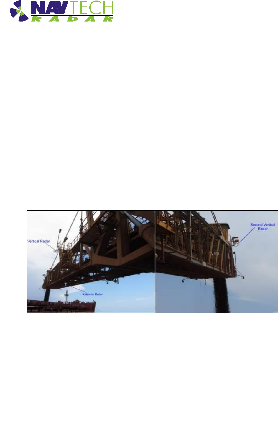
Example 3 – Radar installed on each side of the boom and scanning vertically
For extra protection of bulk loader boom, it is also possible to mount radar that scan through a
vertical plane. These provide protection in the following cases:
The distance between the underside of the boom, and the deck of a vessel it is handling will
be continually measured. If the boom luffs towards the ship, the crane motion can be
stopped. Although the horizontally scanning radar in Figure 4 will protect a luff motion onto a
vertical spar, it won’t be adequate to stop luffing onto the deck or a hatch cover.
As well as during a luff movement, the distance between boom underside and loader may
become too close as the boom long travels or slews along the vessel. This is particularly the
case if the vessel bow is raised in relation to the stern, as the stern is loaded with heavy bulk
first (or vice versa)
The distance between boom underside and vessel can reduce to an unsafe separation in the
event that the tide changes, or the vessel is unloading and it raises on the waterline
Figure 6 This loader is shown with combined horizontal and vertical scanning radar
Health & Safety
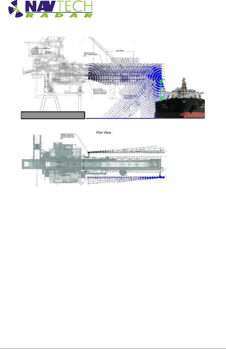
Installation Guide –I Series 2-8
Doc ref: MAINT- 0111 Issue 1.2
Figure 7 The scan plane of vertically scanning radar sensors
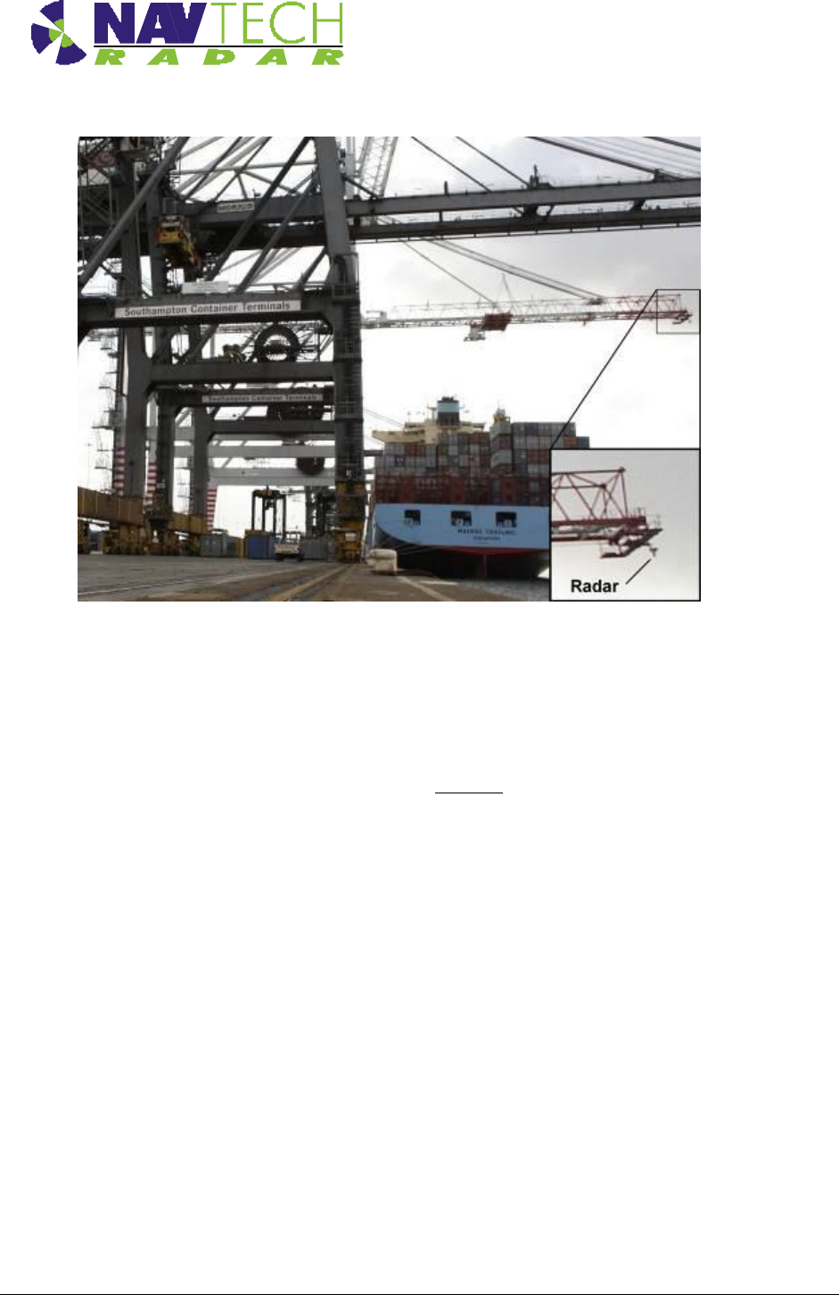
Example 4 – A single radar at the end of a boom structure
A single radar mounted on the underside of the boom, scanning a horizontal plane. This
configuration is usually used on Ship to Shore container handling cranes. These cranes do not
luff, or slew, but it is the long travel movement that needs protecting, since the crane may long
travel into the ship structures in extreme conditions.
It is necessary to mount the radar at the end of the boom, to avoid obstructing the free
movement of the trolley on the underside of the boom. However in this configuration, as the
trolley approaches the end of the boom, the radar is obscured and then offers little protection.
Many operators are of the opinion that the driver is well place in this location to have a good
field of view of the vessel. As the trolley moves off the boom, the driver is further form the
objects he needs good sight of, but the radar then has a completely clear view of the vessel,
offering comprehensive detection. The alternative to having the trolley obscure the single radar
at the boom tip, would be to use 2 radar as shown in Figure 5
Health & Safety
Installation Guide –I Series 2-9
Doc ref: MAINT- 0111 Issue 1.2
Figure 8 Single Radar on an STS, container handling crane
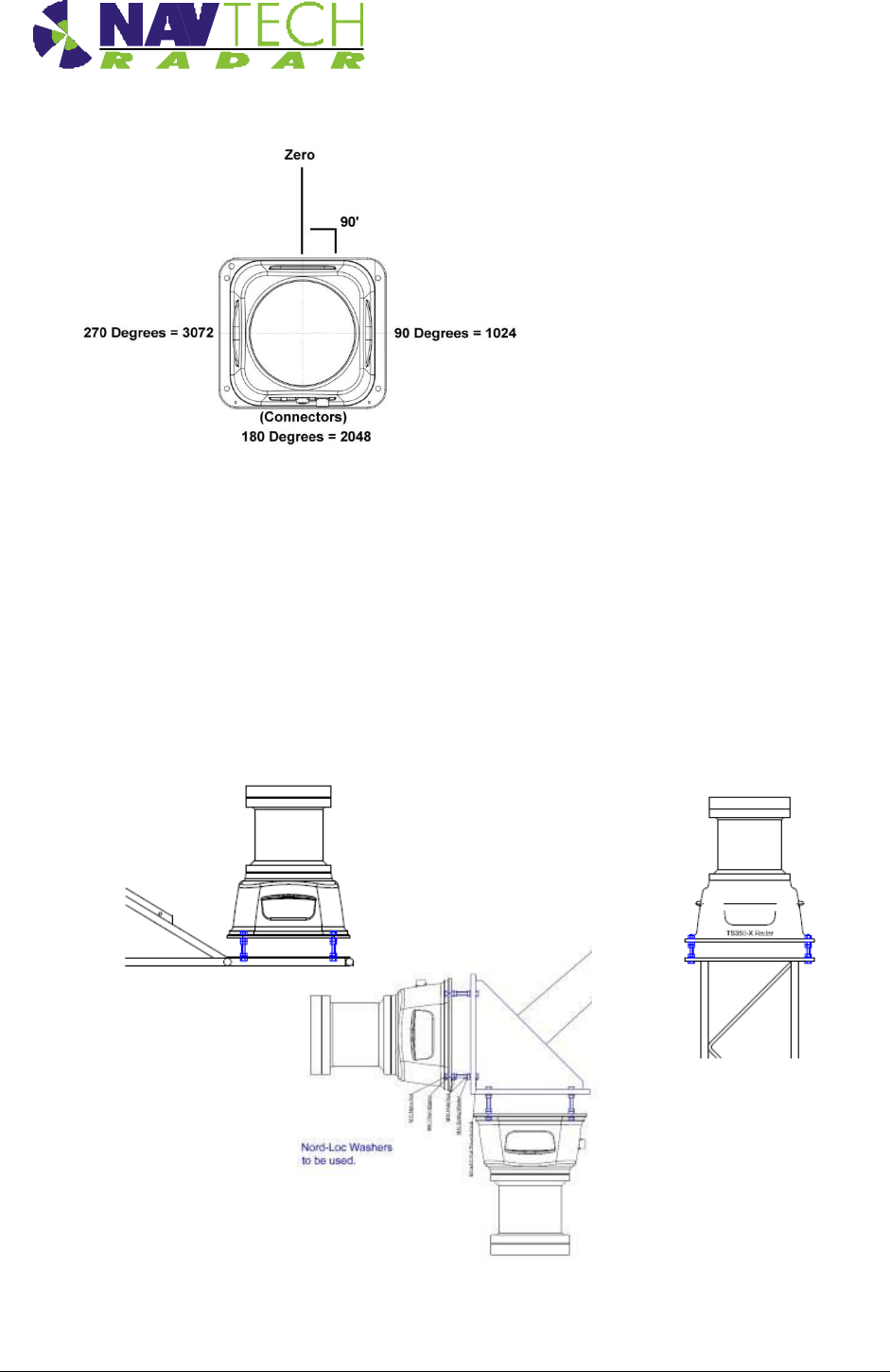
2.2.2 Orientation
The I-series scanning radar sensors, cover 360 degrees whilst rotating. The zero point or 0
degree point is set, at factory, to lie on the opposite side of the radar to the connectors. See
Figure 9. All I-Series radar rotate in a clockwise direction, whether orientated as shown in
Figure 1 or inverted as shown in Figure 3.
It is always helpful when commissioning the radar if the encoder zero is aligned with the boom
or structure it’s to protect. For example, in Figure 3 the zero point should be directed towards
the end of the boom (with the connectors on the quay side of the radar). In this orientation,
objects on the left of the boom will appear on the left hand side of the commissioning interface,
and those physically on the right hand side of the boom will appear on the right of the interface.
Health & Safety
Installation Guide –I Series 2-10
Doc ref: MAINT- 0111 Issue 1.2
Figure 9 Plan view of a radar, showing the encoder zero angle
2.3 Mounting radar sensor
Radar sensors may be mounted on various structures (e.g walls, roofs, gantries) using brackets.
Sample posts and brackets are shown in Annex B.
Radar sensors are fitted to a plate on top of the post, or on the bracket, using nuts and bolts,
which allows you to adjust the tilt [See Figure 11]. Adjusting the tilt (levelling the sensor)
ensures optimum detection performance and is detailed in Section 2.7.
Figure 10 Mounting radar on posts/brackets, for both vertical and horizontally
scanning radar
Health & Safety
Installation Guide –I Series 2-11
Doc ref: MAINT- 0111 Issue 1.2
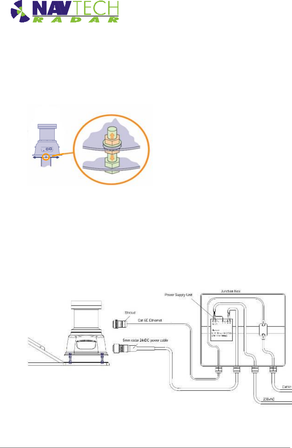
The sensor mounting plate (or bracket) design allows for a simple yet effective method to fine
tune the incline of the sensor. For each of the mounting holes, the bolt is fed from underneath
and locked onto the mounting plate with a nut. Two more nuts are used below the radar base
plate and another is used above so that the sensor can be positioned anywhere up or down the
bolt thread, as necessary.
Figure 11 Levelling adjustment
2.4 Connecting radar sensor
Each radar sensor requires a power and a data connection. Both are made using military
specification connectors to ensure link integrity in the harshest environmental conditions. The
power and data connections run from the sensor to a conveniently placed junction box (e.g.at
the base of the post) where the power supply is situated. See Figure 12.
Figure 12 Connections to radar sensor
Health & Safety
Installation Guide –I Series 2-12
Doc ref: MAINT- 0111 Issue 1.2
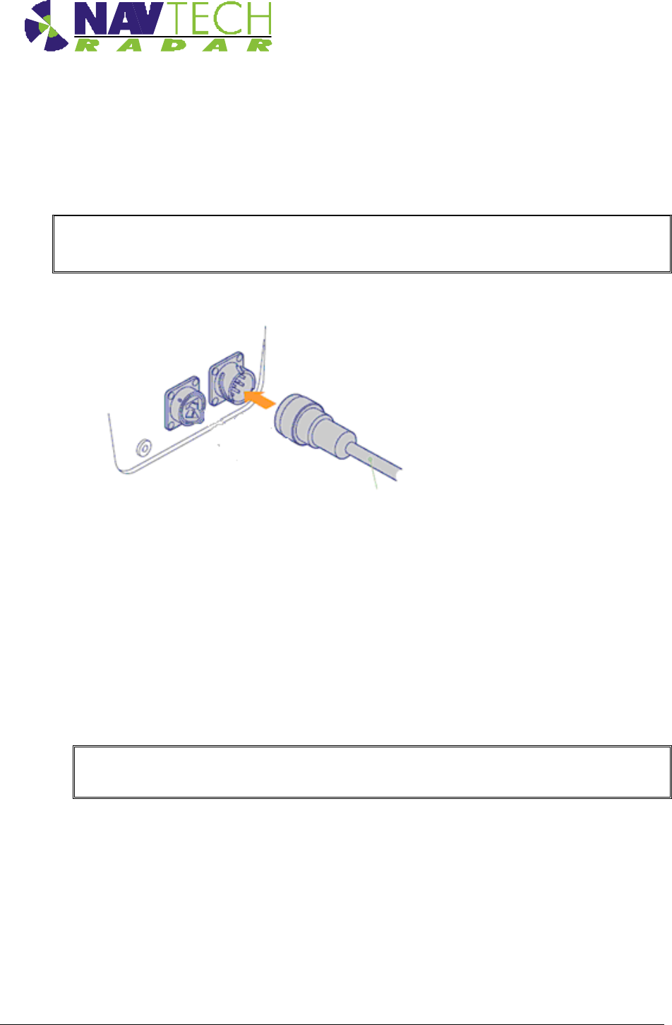
Supplied with each radar sensor are a power cable with a mil-spec connector for the sensor
connection and a bare end at the junction box connection. A mil spec shroud is also supplied for
use with a suitable environmentally protected Ethernet network connection. It is essential that
the supplied shroud is correctly used to ensure that the data connection is water tight.
IMPORTANT: Failure to correctly fit the shroud can invalidate the warranty on sensors that
have been caused to fail through water ingress.
1. Attach 24vDC connection to the radar.
Figure 13 Connecting radar sensor
2. Ensure the Power and Ethernet cables are securely connected into junction box.
3. Ensure the junction box has the Navtech supplied 24vDC power supply installed. (The
power supply unit has a peak current capacity of 4 Amps, though typically the radar
draws a continuous 1 Amp). See.[8].
4. Ensure that the Power supply cabling is correctly terminated at the radar end with a
secure Amphenol MIL spec connector. Pin D (Red or Brown) is 24vDC, Pin J (Blue or
Black) is 0V.
IMPORTANT: To prevent floating voltage levels on the low output of the radar sensor power
supply unit, link the 0v output to earth.
5. Ensure the junction box has an Ethernet cable running to the infrastructure network
switch.

Health & Safety
Installation Guide –I Series 2-13
Doc ref: MAINT- 0111 Issue 1.2
2.5 Preparing the laptop
IMPORTANT: Ensure that your laptop has its IP address set to operate within the same
subnet as the radar sensor
2.5.1 Factory settings
The IP address (e.g. 192.168.0.1) of the radar sensor is preset before leaving Navtech Radar
Limited according to client specifications and will be declared on a label attached to the outer
casing.
The subnet mask of the radar sensor is often preset to 255.255.255.0 but could also be set
wider (such as 255.255.0.0) if requested. Therefore, if the sensor IP address is 192.168.0.1 and
the mask is 255.255.255.0, then your computer must use an IP address in the range:
192.168.0.2 to 192.168.0.254.
2.5.2 Changing factory settings
The IP address and subnet mask can be changed using firmware commands sent to the radar
either via Telnet (see [5]), or using a serial connection (see [D3]).
2.6 Connecting your laptop
1. At the radar, connect the laptop via CAT5 cable to the radar.
2. Ensure that the radar sensor is powered on and is rotating - you can faintly hear the rotor
when it is running.
3. Use SPx Radar View application [1] to display the radar data. (See Annex A )
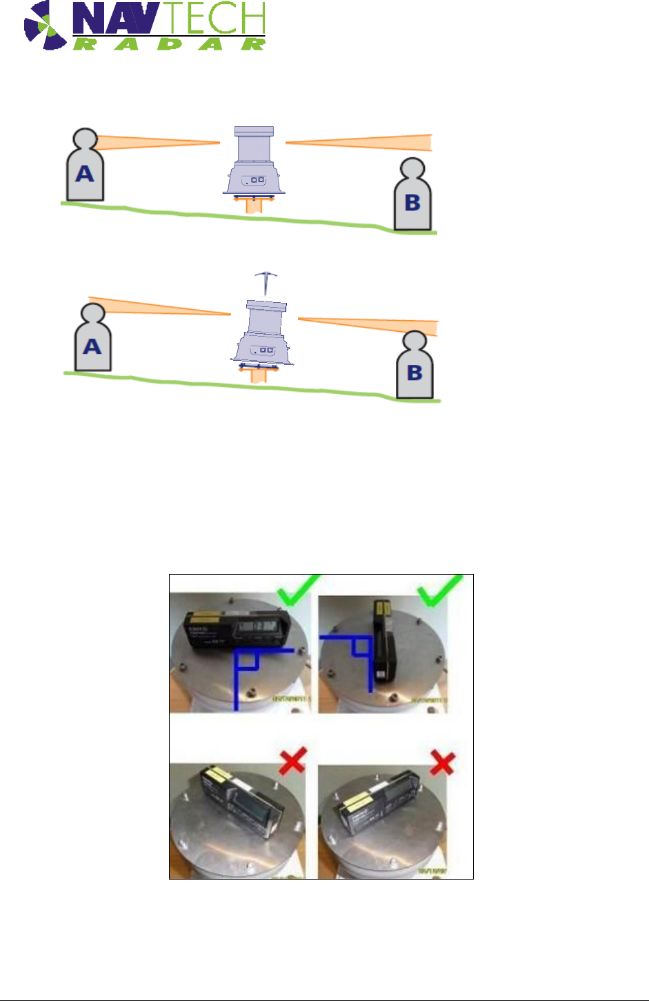
2.7 Levelling radar sensor
For optimum detection performance it is important that each sensor is level in relation to the
area that it surveys. Level in this sense may not mean absolutely horizontal, generally the radar
will be levelled so as to scan parallel to the boom they are to protect.
The exaggerated examples below show how a sensor with an incorrect incline could miss
targets which are lower down the slope:
Health & Safety
Installation Guide –I Series 2-14
Doc ref: MAINT- 0111 Issue 1.2
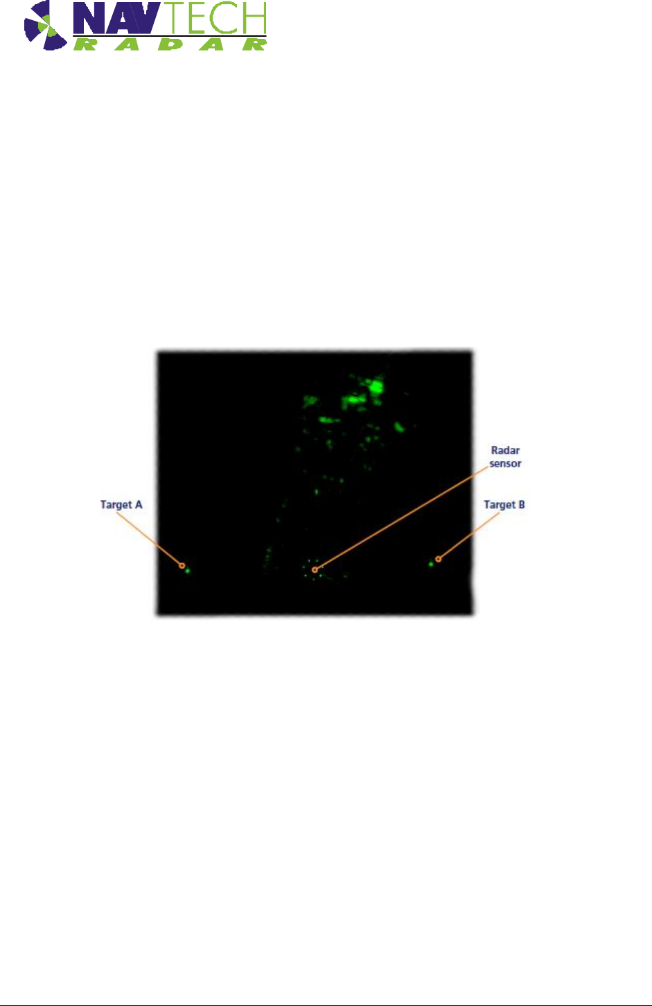
Figure 14 Horizontal radar sensor misses target B
Figure 15 Inclined radar sensor locates both targets
A Digital Level as indicated in Figure 16, can be used to ensure the radar is installed level. This
should be checked in two axes, on the radar lid, as shown below. The objective is to install the
radar so that it scans in a plane which is parallel to the boom or structure which is being
protected
Figure 16 Digital Inclinometer mounted on radar sensor
Health & Safety
Installation Guide –I Series 2-15
Doc ref: MAINT- 0111 Issue 1.2
2.7.1 Adjusting radar
Once installed on the machine, fine adjustments of the radar level may be needed. These are
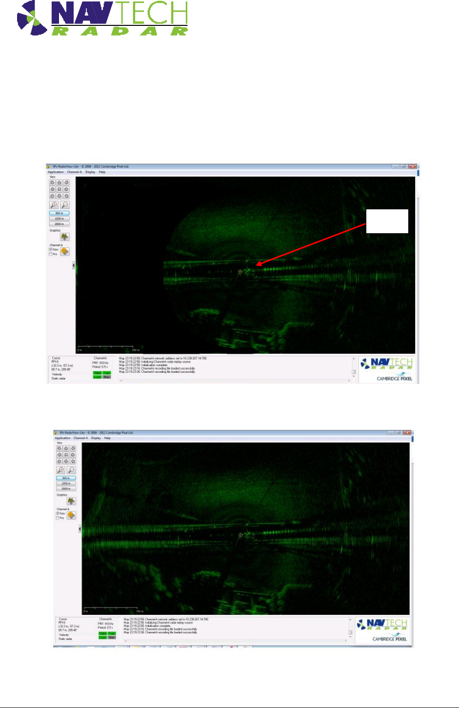
best made with reference to the actual radar image, as viewed in RadaView test software
Figure 17 SPx RadarView display (A)
Figure 18 SPx RadarView display (B)
Radar
Health & Safety
Installation Guide –I Series 2-16
Doc ref: MAINT- 0111 Issue 1.2
Using the RadarView application to view the radar data (see Annex A), you are aiming to have
an equal amount of data either side of the radar.
1. If there is more radar data one side than the other, as shown in Figure 17, change the
angle of the radar until you have an equal amount of data either side of the radar, as
shown in Figure 18. Radar targets can be used as the test object.
2. If there is not enough radar image to view from objects/structures already within the radar
line of sight, test targets can be used instead. Adjust the radar tilt of the radar on the
threaded studs, to maximise the signal level on the 2 targets are determined from the
RadarVew software (See Annex A for detailed instruction).
Figure 19 Radar view to locate target
2.8 Securing the radar
1. Secure the radar on the mounting bracket, or post plate. To do this: lock off the two lower
nuts on each stud by tightening one against the other. (This is to ensure that, if the radar
is removed, the tilt angle is not changed)
2. Record the tilt angle from the digital inclinometer. See Annex E for a sample table.
2.9 Confirming sensor coverage
1. Install and configure the witness software as described in [2].
2. Enter basic detection areas into the witness interface. (See [2]).
3. Where possible, place test objects into the radar detection zone. Monitor these on the
interface and confirm that detection alarms are raised

Health & Safety
Installation Guide –I Series 3-17
Doc ref: MAINT- 0111 Issue 1.2
4. Refine the radar detection zones, based on the tests and save the settings.
5. Disconnect the laptop from the radar and connect the radar to the infrastructure network
switch.
6. Repeat for each radar
3. Health & Safety
3.1.1 General
1. A first aid kit should be available at all times.
2. In addition to the conditions detailed in this section the Site Safety Procedures for the
location where the equipment is being installed must be complied with at all times.
3.1.2 Design
The design and manufacture of all equipment supplied as part of the Navtech radar tracking and
monitoring system for permanent installation is CE accredited:
European Electromagnetic Compatibility Directive 89/336/EEC
ETSI EN301 091-1 Electromagnetic compatibility and Radio Spectrum Matters Short
Range devices
3.1.3 Maintenance
1. Make sure that electrical supplies are properly isolated before removing any covers. The
supply should be disconnected by the operation of the main isolating switch, removal of
fuses or other acceptable method. A notice should be placed at the point of isolation
showing:-
DANGER - WORK IN PROGRESS
2. Place a barrier or guard rail round the work area.
3. When working on elevated equipment, make sure that all ladders and staging are secure.
If necessary, wear a safety harness.
4. Be aware of any special hazards specific to the site or location where equipment is
located. Take all necessary precautions.
Annex A
Installation Guide – I Series A -1
Doc ref: MAINT- 0110 Issue 1.2
Annex A Using SPx RadarView
The SPx RadarView application consists of two files which must be located in the same folder (any folder)
on your laptop:
SPXRadarView.exe
SPXRadarView.rpi
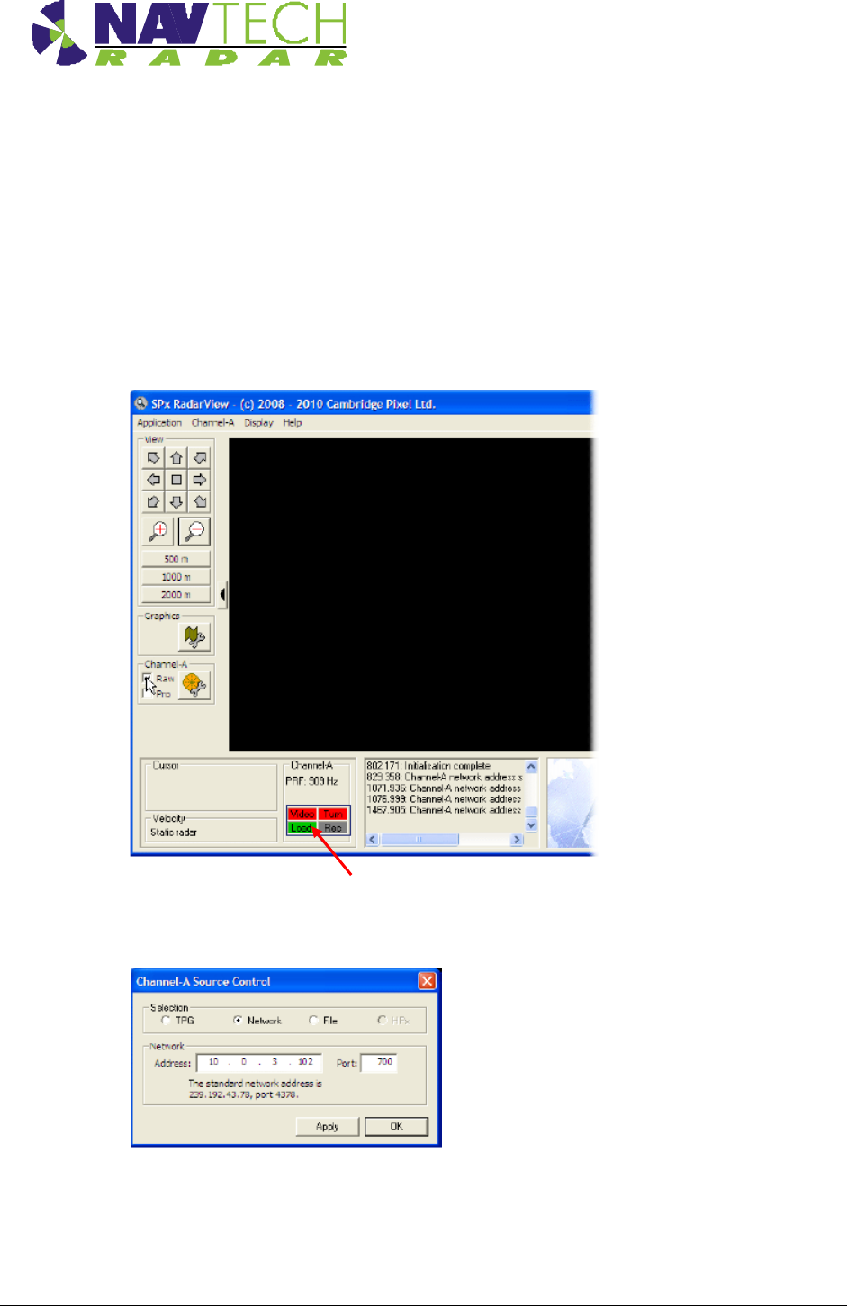
1. Run SPXRadarView.exe. You should see a blank main screen:
Note: In the lower panel, the Video and Turn indicators will be red indicating that
there is no communication with the sensor.
2. Click the Channel-A menu on the toolbar, and select the Source... option.
Ensure that the Selection option is set to Network and in the Address field,
enter the IP Address of the sensor. The Port must be set to 700.
Click OK.
Annex A
Installation Guide – I Series A -2
Doc ref: MAINT- 0110 Issue 1.2
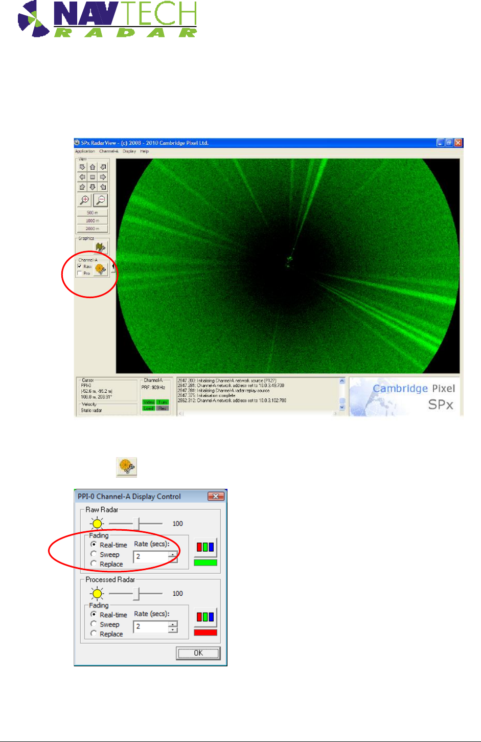
Once the IP address and port are correctly set and the application makes contact with the
sensor, the Video and Turn indicators should turn green. Shortly afterwards, you should
begin to see radar scan information within the main window.
On the left side of the screen, ensure that the Raw option is ticked.
3. Click the button to show the Display Control dialog box:
Ensure that in the Raw Radar section, the Fading option is set to Sweep and the Rate
(sweeps) is set to 5. Click OK.
Annex A
Installation Guide – I Series A -3
Doc ref: MAINT- 0110 Issue 1.2
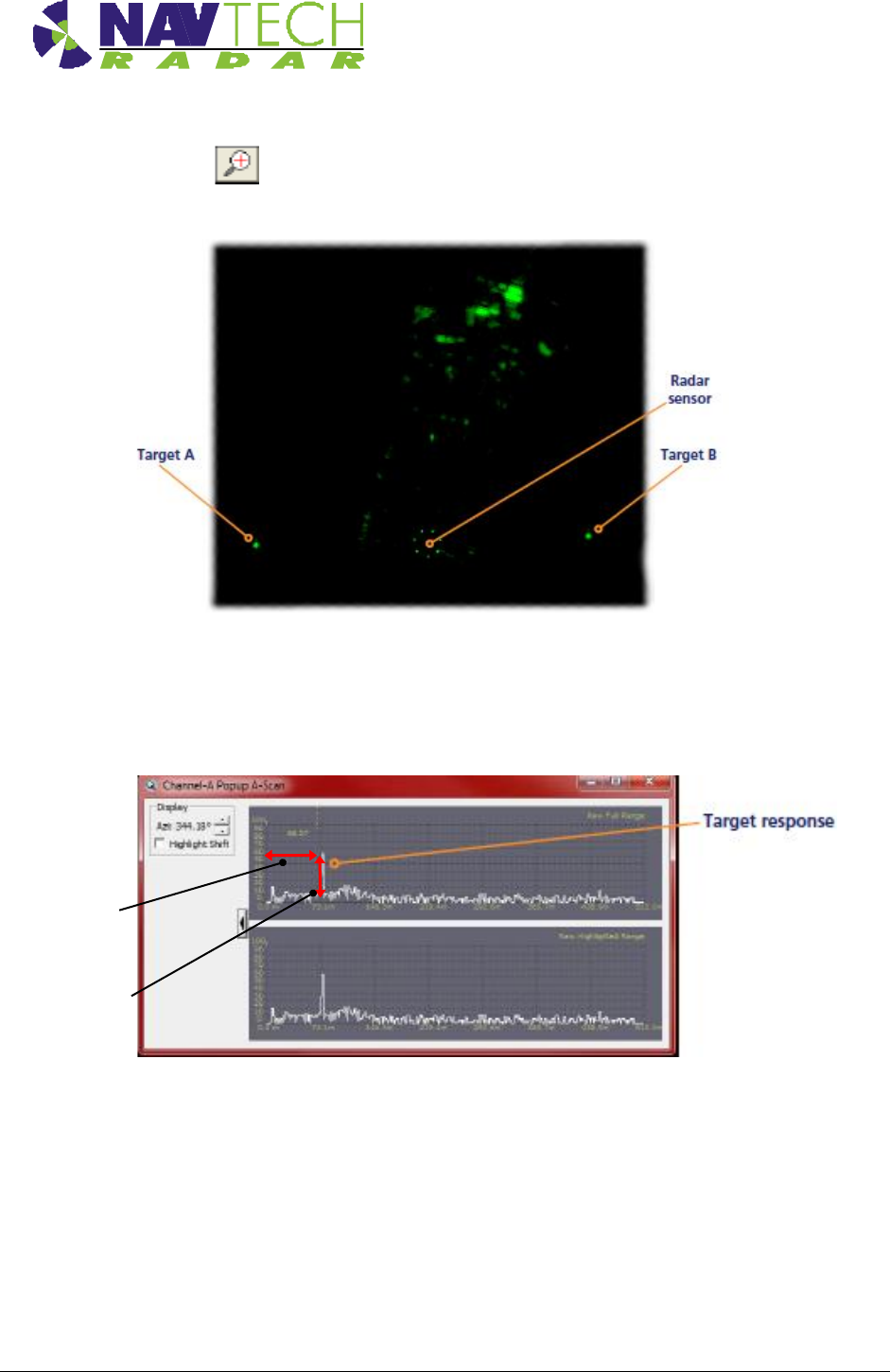
4. Click the button to zoom into the radar view so that you can clearly see the both of
your test targets:
5. Right click the mouse pointer on the exact middle point of one of the targets to display a
popup options box. Click the option Popup Channel-A AScan…. to display a scan
window.
The scan window provides live signal strength data concentrating only on the angular
direction of the chosen target from the radar sensor. In each of the two graph plots, the
x-axis shows the distance from the sensor while the y-axis indicates the returned signal
strength. You should see a spike representing your target at the relevant distance.
Signal strength dB
Distance from
radar m
Annex A
Installation Guide – I Series A -4
Doc ref: MAINT- 0110 Issue 1.2
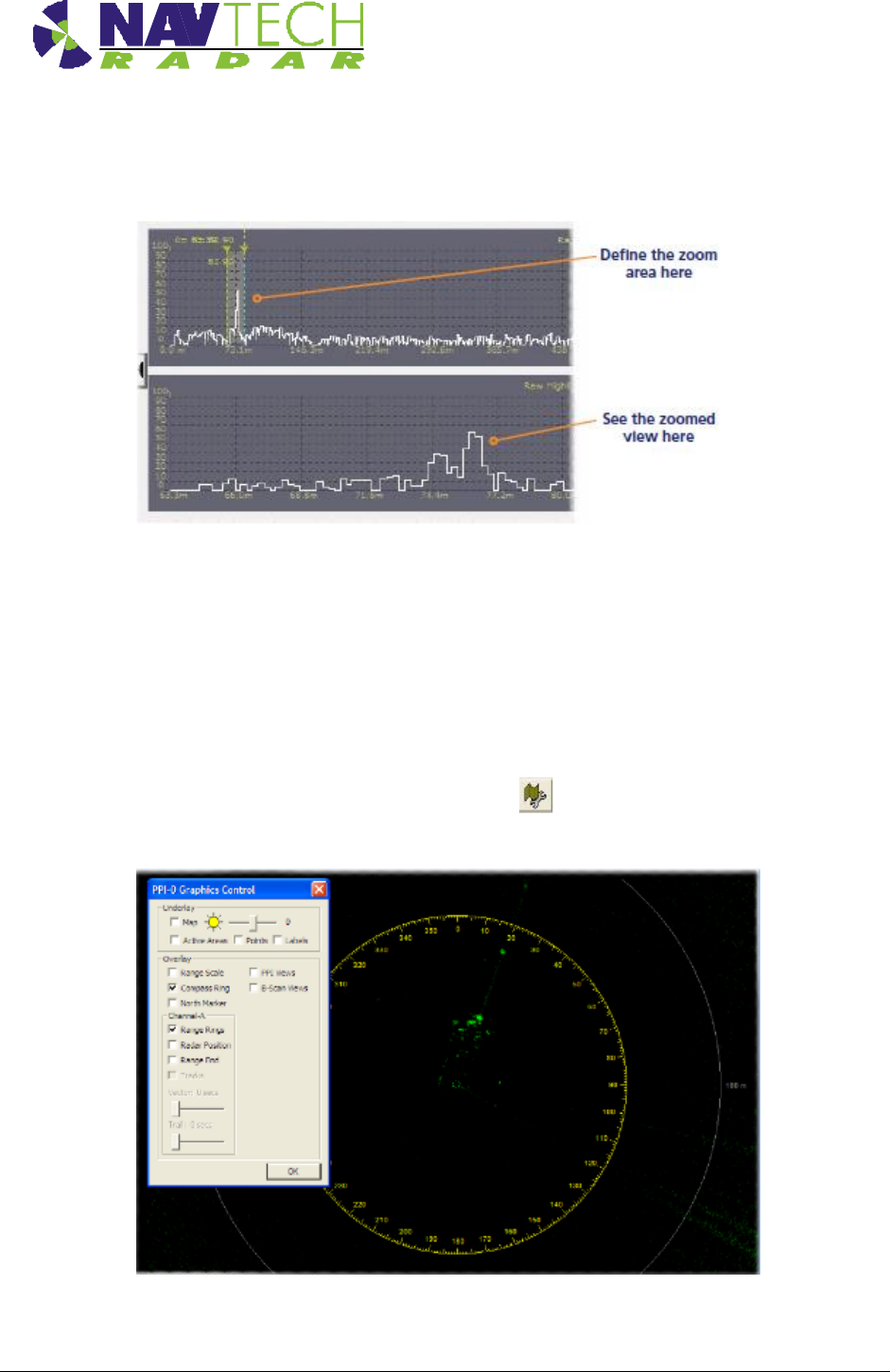
6. On the top graph, left click on either side of the spike to create a zoomed view on the
lower graph.
This will allow you to see small changes in the returned signal strength on the lower
graph when levelling the sensor:
7. Repeat steps 5 and 6 for the other target so that you can view both on screen at the
same time.
8. Adjust the radar sensor level (See Section 2.7) while checking the scan graphs to ensure
the best response from both targets.
9. To assist with orientation, optionally click the button to show the Graphics Control
dialog box:
Two options within this dialog box are of particular use:

Annex A
Installation Guide – I Series A -5
Doc ref: MAINT- 0110 Issue 1.2
- Enable the Compass Ring option to superimpose compass graduation marks
around the sensor view.
Note: North is aligned to the zero point of the radar sensor, not magnetic
north.
- Enable the Range Rings option to overlay range lines every 100m onto the sensor
view
Annex B
Installation Guide – I Series B -1
Doc ref: MAINT- 0111 Issue 1.2
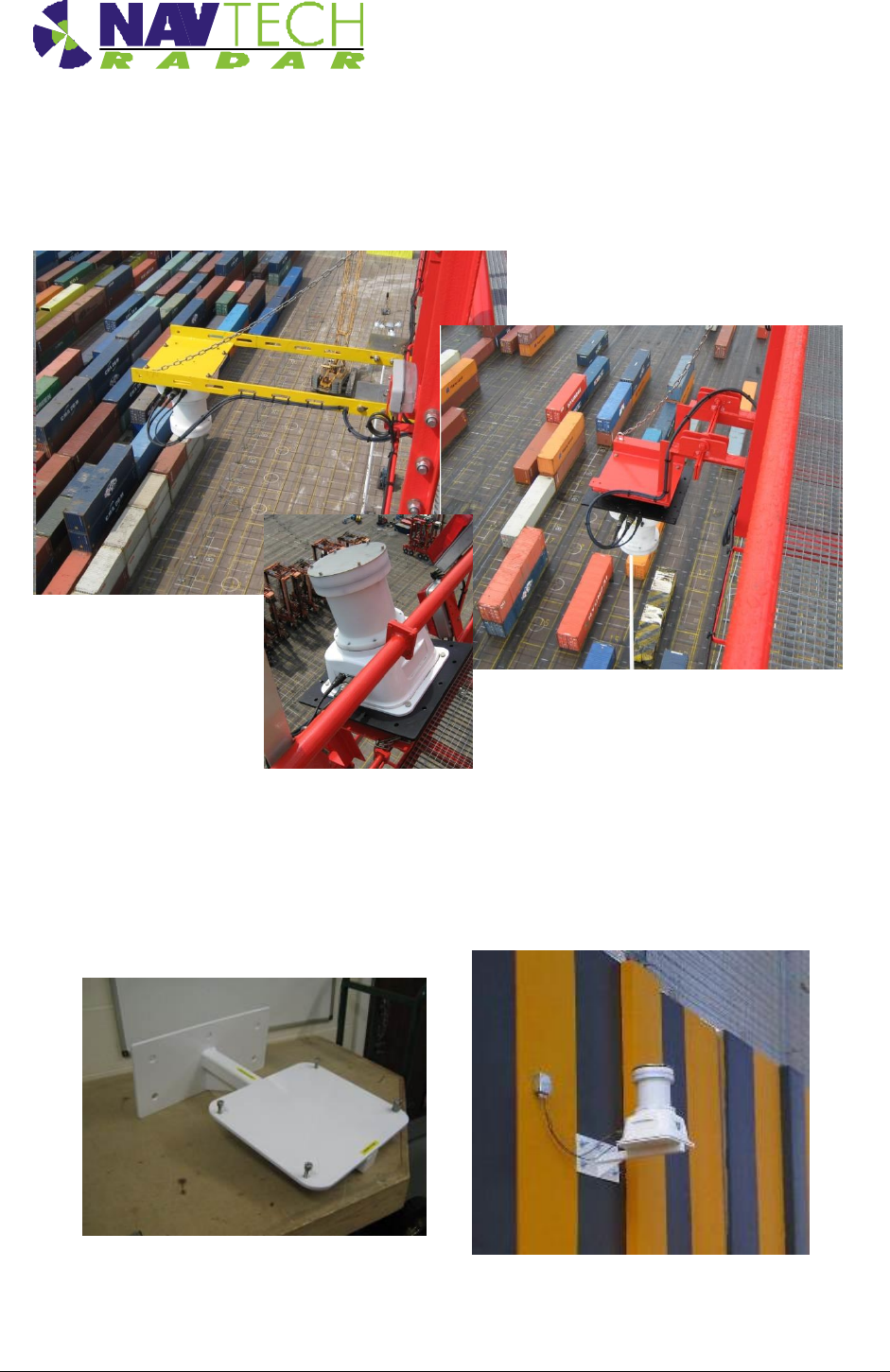
Annex B Sample Brackets
Figure 20 I-200 mounted on a ship to shore container crane.
Shown in the deployed position (above) on 2 different bracket
arrangements and recovered for maintenance (below)
Figure 21 Mounting bracket, and installed on a wall
Annex B
Installation Guide – I Series B -2
Doc ref: MAINT- 0111 Issue 1.2

Annex B
Installation Guide – I Series B -3
Doc ref: MAINT- 0111 Issue 1.2
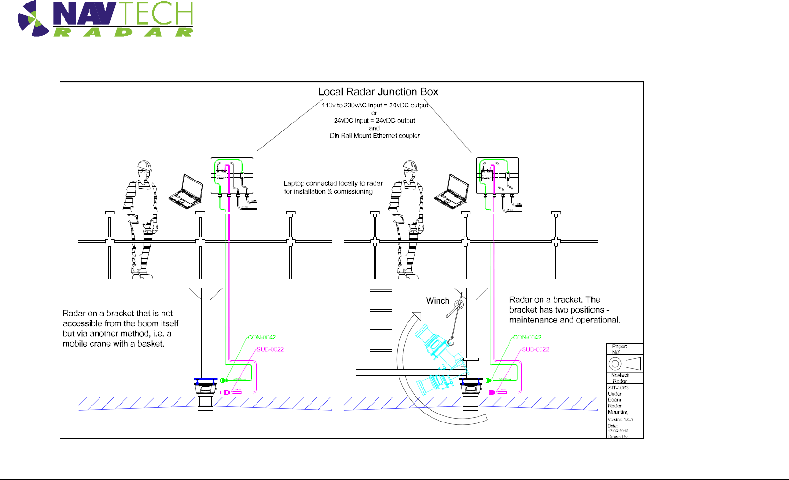
Figure 22 Two possible methods of mounting a radar centrally, under the boom

Annex C
Installation Guide – I Series C -1
Doc ref: MAINT- 0111 Issue 1.2
Annex C Specifications
This Annex contains the specifications for the cables and connectors supplied by Navtech, with the
exception of the Ethernet connector which is a standard RJ45 connector.
C.1 Radar power cable
318-B LSZH cable
Part no
Eland A5Z02015BK
No of Cores x Nominal Cross Sectional
Area
2 x 1.5 mm2
Core Identification
2 cores: Blue, Brown
Current carrying capacity
Single phase AC 16 amps
Insulation
LSZH ( application dependent )
Sheath
LSZH ( application dependent )
Standard
IEC 60092-353
Conductor
Class 5 flexible plain copper to BSN EN 60228:2005
Table 2 Radar power cable specification
C.2 Radar Cat 5E cable
Cat 5E cable
Part no
Eland A8NCAT5EFTPGSWB
No of pairs
4
Core Identification
4 pairs: Blue + White/Blue, Orange + White/Orange, Green +
White/Green, Brown + White/Brown
Standards
ISO/IEC 11801, TIA/EIA 568B
Braiding
GSWB (Galvanised Steel Wire Braid)
Sheath
LSZH ( application dependent )
Sheath colour
Black
Table 3 Radar Cat 5E Ethernet cable specification
C.3 Radar power cable connector (radar end)
Amphenol 97 series
MIL Spec
MIL-C-50152
Model
3106A
Operating temperatures
–55°C to +125°C
Power pins
Pin D (Red or Brown wire) & Pin J (Blue or Black wire)
Design Characteristics
10 socket plug, Single key/keyway polarization
Threaded coupling, hard dielectric inserts
Table 4 Radar power cable (radar end) connector specification

Annex C
Installation Guide – I Series C -2
Doc ref: MAINT- 0111 Issue 1.2

Annex C
Installation Guide – I Series C -3
Doc ref: MAINT- 0111 Issue 1.2
C.4 Radar Cat 5E cable connector (radar end)
Amphenol RJF series
Part No
RJF6
MIL Spec
MIL-C-26482
Data Transmission
Category 5e per ISO/IEC 11801
Mechanical
Bayonet coupling (Audible & Visual coupling signal)
4 mechanical Coding / Polarization possibilities by the user (insert
rotation)
RJ45 cordset retention in the plug : 100 N in the axis
Mating cycles : 500 min
Environmental Protection
Sealing: IP67
Salt Spray : 48 h with Nickel plating> 96 h with black coating> 500 h
with hard anodic coating and Cadmium
Fire /Low Smoke: UL94 V0 and NF F 16 101 & 16 102
Vibrations : 25 –250 Hz, 5 g, 3 axes : no discontinuity> 1μs
Humidity: 21 days, 43°C, 98%humidity
Rapid change of Temperature: 5 –20°C / +85°C cycles
Table 5 Radar Cat 5E cable connector (radar end) specification
Annex D
Installation Guide – I Series D - 1
Doc ref: MAINT- 0111 Issue 1.2
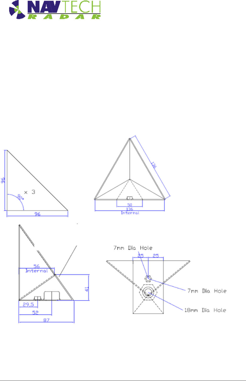
Annex D Construction of test target
The following drawings show how to construct a test target.
Tolerance: +/- 1mm on linear dimensions
Material: 1.5 stainless
Finish: Bare metal
The target can be made by welding 3 flat triangles together, or by folding one piece and welding the
meeting edges:
The lower piece can overlap on to the back of
the target to ease production and increase
strength
Back of
target
Welded on ¼ Whitworth and 5/8th UNC
stainless nuts

Annex E
Installation Guide – I Series E- 1
Doc ref: MAINT- 0111 Issue 1.2
Annex E Radar sensor configurations
A sample table to record data for each radar.
Radar
Sensor
Serial
No
IP Address
Subnet Mask
Approximate
Geographical position
Lat(N) Long (E)
Radar Base
Plate Angle
(deg)
Example
100
192.168.1.170
255.255.255.0
59.25023
17.85109
+1.5
A1
A2
A3
A4
Annex F
Installation Guide – I Series F - 1
Doc ref: MAINT- 0111 Issue 1.2
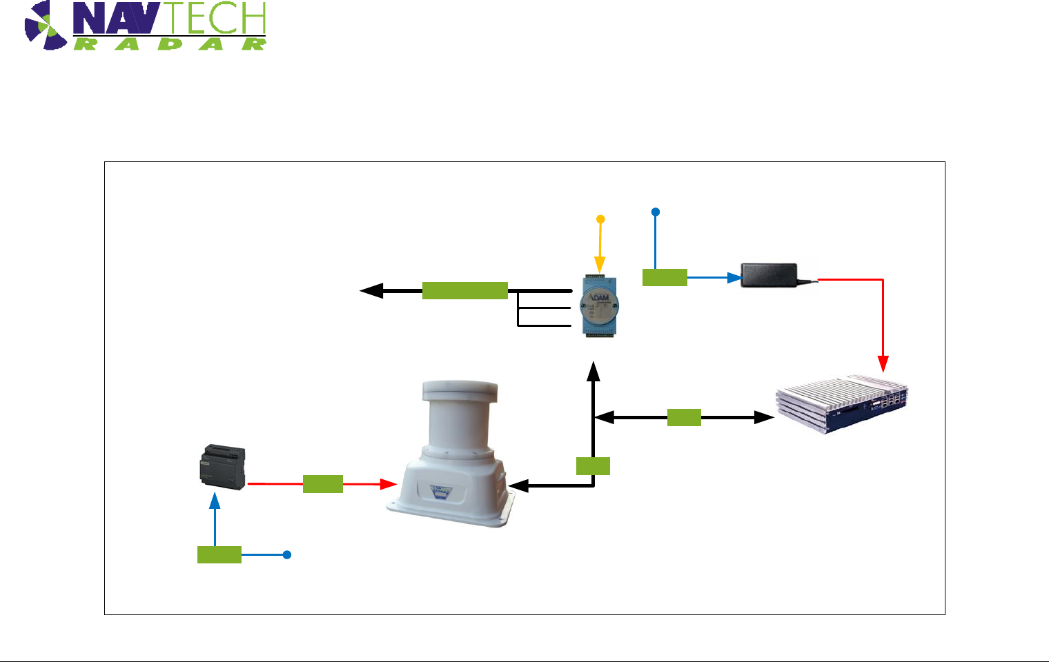
ANNEX – F Outline System Diagram
230vAC
LPU PSU
10 to 30vDC
(250mA Each)
Alarm Outputs
LPU
Computer
ANC-0015
Cat5e
Cat5e
24 Vdc
230vAC
Radar PSU
ANC-0024
I-200 Radar
NAV-0005
Relay
Output
ANC-0024

Annex G
Installation Guide – I Series G - 1
Doc ref: MAINT- 0111 Issue 1.2
ANNEX – G Radio Frequency Energy Compliance
FCC compliance statement (United States)
This device complies with Part 15 of the FCC Rules. Operation is subject to the following two conditions:
(1) This device may not cause harmful interference, and
(2) This device must accept any interference received, including interference that may cause
undesired operation.
The operation of this device is limited to a fixed position at airport locations for foreign object debris
detection on runways and for monitoring aircraft as well as service vehicles on taxiways and other airport
vehicle service areas that have no public vehicle access. This equipment must be mounted in a fixed
location maintaining a minimum separation distance of 40cm from personnel when in general
operation. This restriction of operation is specific for use in North America. For use in other regions
aligned to the FCC regulations, specific country restrictions should be reviewed.
Changes or modifications not expressly approved by the party responsible for compliance could void the
user’s authority to operate the equipment.