Nec Nd 71762E Users Manual NEAX 2400 IPX No.7 CCIS System
ND-71762(E) to the manual 57e3952d-4482-4844-85c1-0acf0579a312
2015-01-24
: Nec Nec-Nd-71762E-Users-Manual-331838 nec-nd-71762e-users-manual-331838 nec pdf
Open the PDF directly: View PDF ![]() .
.
Page Count: 138 [warning: Documents this large are best viewed by clicking the View PDF Link!]
- No.7 CCIS System Manual
- CHAPTER 1 INTRODUCTION
- CHAPTER 2 GENERAL INFORMATION FOR CCIS
- 1. GENERAL
- 2. DESCRIPTION OF CCIS
- 3. SYSTEM CONFIGURATION
- 4. NETWORK CONFIGURATION
- 5. DIGITAL NETWORK AND NETWORK SYNCHRONIZATION
- 6. NETWORK THROUGH FCCS GROUPS AND NEAX2000 IPS Internet Protocol Server
- CHAPTER 3 SWITCH SETTING SHEETS
- CHAPTER 4 INSTALLATION PROCEDURE
- CHAPTER 5 INSTALLATION TEST PROCEDURE
- CHAPTER 6 BASIC DATA ASSIGNMENT
- CHAPTER 7 CCIS SERVICE FEATURES
- CHAPTER 8 MAINTENANCE PROCEDURE

ND-71762(E)
ISSUE 2
No.7 CCIS System Manual
AUGUST, 2002
NEC Corporation
To view the latest issue of this document go to NEC Knowledgebase @ http://www.kbase.cns.nec.com.au &search for NEC-7141
LIABILITY DISCLAIMER
NEC Corporation reserves the right to change the specifications,
functions, or features, at any time, without notice.
NEC Corporation has prepared this document for use by its employ-
ees and customers. The information contained herein is the property
of NEC Corporation and shall not be reproduced without prior written
approval from NEC Corporation.
All brand names and product names on this document are trade-
marks or registered trademarks of their respective companies.
Copyright 2002
NEC Corporation
ND-71762 (E) PRODUCT LIABILITY
PL- 1
Issue 2
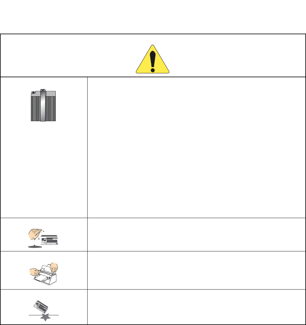
PRODUCT LIABILITY
BEFORE THE USE OF THIS MANUAL
1. FOR SAFETY USE
Here explains the safety use for the customer, which prevents danger to the life and damage to the property ac-
cidentally. The following are symbols and their meanings. Please read the following carefully before using this
manual.
SYMBOLS DESCRIPTION
DANGER
This symbol indicates danger. You might be involved in a situation that
could cause deadly and bodily injury if you take wrong action.
WARNING
This symbol indicates warning. You might be involved in a situation that
could cause bodily injury and serious system fault if you take wrong ac-
tion.
ATTENTION
This symbol indicates attention. The system might not acheive its perfor-
mance or lead to the system stall if you take wrong action.
This telephone system is designed for use in the country NEC provides and can not be used in any other country.
If system-down, malfunction, defects, and external factors (such as electricity failure) cause profit loss indirectly, NEC does
not take any responsibilities for the profit loss.
We pay careful attention to making this manual, however, when you find mistakes on this manual, notify to NEC.
Contact the supplier or the service technician if the system needs repairs and installation.
Please read all the manuals related to your system carefully.
PRODUCT LIABILITY ND-71762 (E)
PL- 2
Issue 2
PRODUCT LIABILITY
2. NOTICE WHEN USED
2.1 Consideration of PBX, Power-related Equipment and Peripheral Equipment
This item describes the consideration before using PBX, the power-related equipment, and the peripheral equip-
ment (such as console, MDF, DAU, telephone, PC, printer, etc).
Preserve the following:
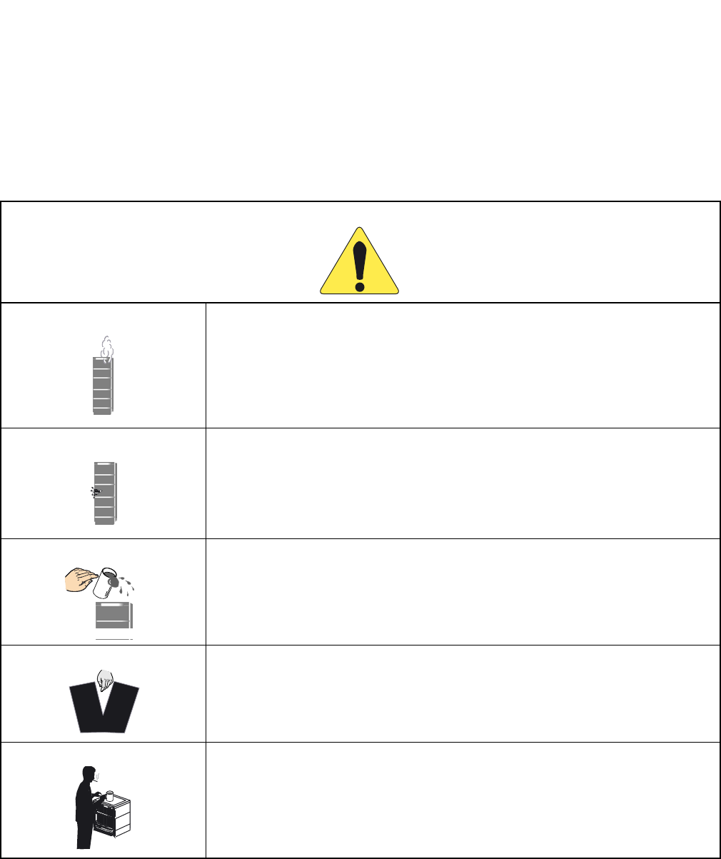
DANGER
When the system gives off smoke or burning smell, it might cause a fire, an electric
shock, or a failure if the system keeps operating. Turn off the power and confirm the
smoke disappears, and then contact supplier.
If equipment (such as PBX, Main Power, cabinet, and peripheral equipment) fall down
and be broken, turn off the power, and then contact the supplier.
If the inside of PBX or Main Power is wet by liquid such as water, turn off the power.
It might cause a fire, an electric shock, or a failure if the system keeps operating.
Do not touch the internal parts of Main Power for the purpose of disassembly and re-
modeling. It might cause a fire, an electric shock, or a failure.
(NEC does not take any responsibilities if the system or the equipment is disassembled
or remodeled.)
Do not put any container (such as vase, cup, and cosmetics) on Main Power and periph-
eral equipment. It might cause a fire, an electric shock, or a failure.
PWR
ND-71762 (E) PRODUCT LIABILITY
PL- 3
Issue 2
PRODUCT LIABILITY
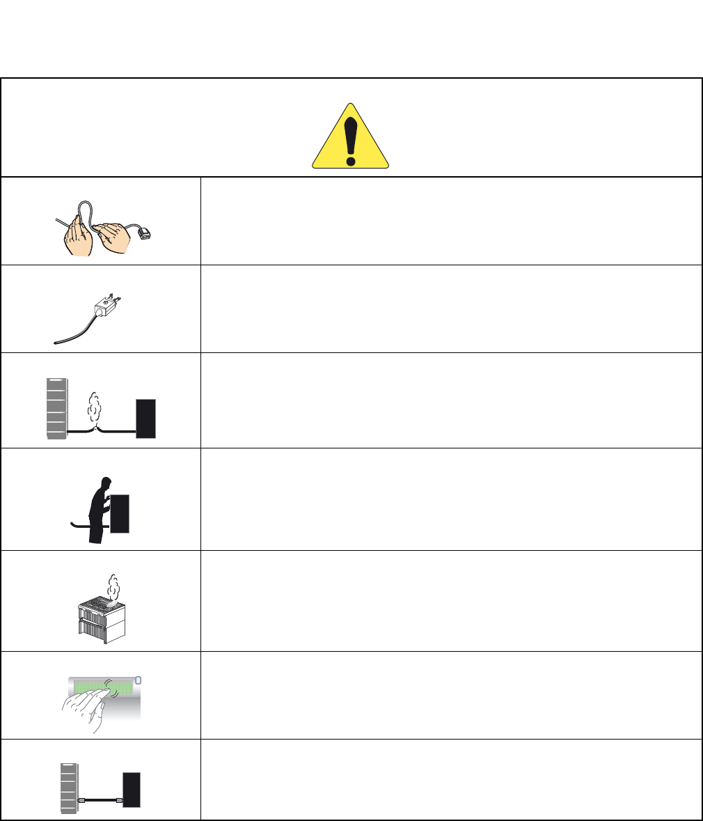
DANGER
Do not damage, remake, forcefully bend, forcefully extract, nor forcefully twist an elec-
tric code and a wiring to/from PBX, Main Power and peripheral equipment. It might
cause a fire, an electric shock, or a failure. If the wiring is damaged, ask the supplier to
fix it.
Insert the electric plug into the outlet properly. Confirm no dust is on the blade of plug;
it might cause a fire.
Do not use other than the power designated when installed.
Do not try to fix or move Main Power by yourselves without the supplier or service tech-
nician’s help. Please ask them when the repair or the movement is necessary.
Do not put any metal or combustible object into a vent of PBX, Main Power, and the
peripheral equipment. If the object is in those equipment, turn off the power and ask the
supplier. It might cause a fire, an electric shock, or a failure if the system keeps operat-
ing.
Be careful of using the display part which the peripheral equipment has. In the case of
liquid crystal, the liquid is leaked and causes harm to human body and systems.
Before connecting customer-provided equipment (such as the other company products)
with NEC products such as PBX and peripheral equipment, ask the supplier and make
sure your equipment is compatible with NEC product. If it is not confirmed, do not con-
nect them. It might cause a fire or an electric shock.
dust
PWR
PWR
?
PRODUCT LIABILITY ND-71762 (E)
PL- 4
Issue 2
PRODUCT LIABILITY
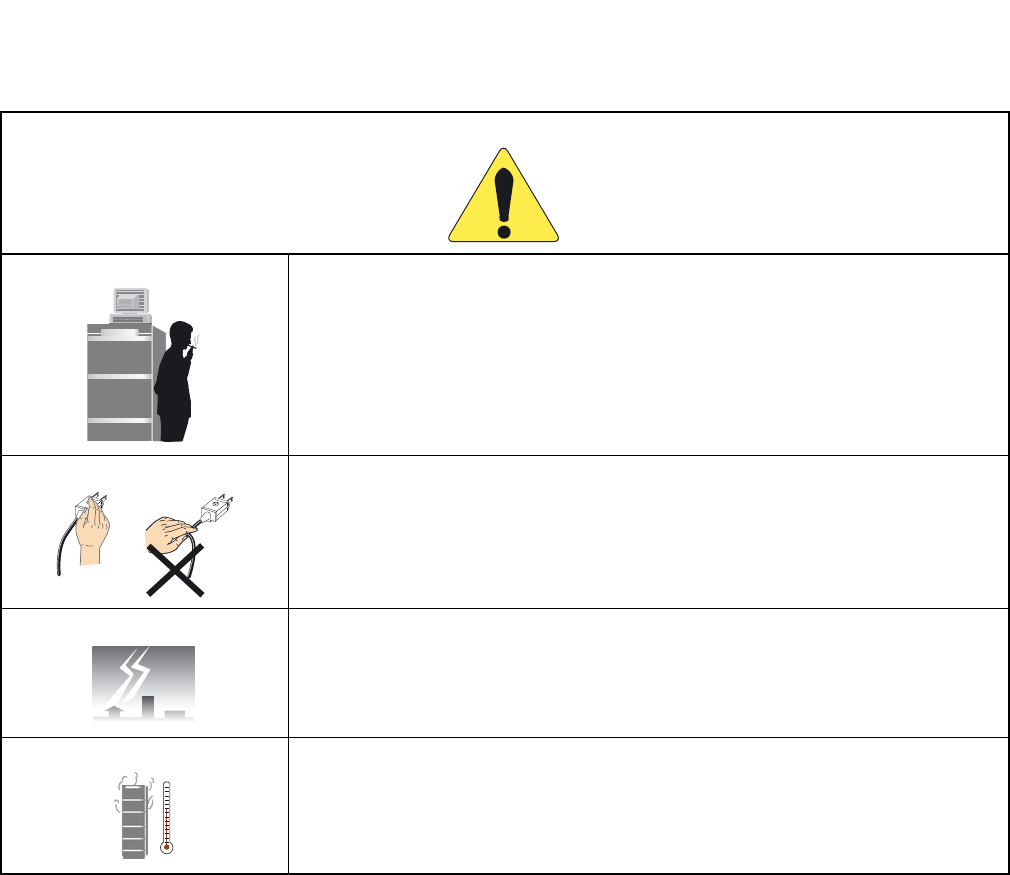
WARNING
Fix the equipment. Do not put any object on PBX and Main Power; it might be danger-
ous if the object should fall down.
When plugging off a plug, be sure to grip the plug and extract it. If you grip the code
and extract it, it might cause a fire and an electric shock.
If a fault is considered as the lightening cause, ask the supplier.
Other than fulfilling the appropriate humidity and temperature, it is necessary to consid-
er the maintenance operation and the all-time ventilation in non-loading operation dur-
ing day-off and night. For example, when the height above floor is 1 m (3.281 feet), the
temperature should be from 20 to 25 °C (68 to 77 °F ) and the humidity should be more
or less 50 %.
ND-71762 (E) PRODUCT LIABILITY
PL- 5
Issue 2
PRODUCT LIABILITY
WARNING
Be careful of using a battery as following:
Rechargeable lead battery is used as the emergency battery of PBX. Check the back-
up for an electricity failure.
Battery electrolyte is harmful to human body. If the battery electrolyte is put on the
cloth, clean it using enough amount of water.
Do not cause the battery short intentionally. Do not put it near fire or put it into fire.
Do not damage it, such as disassembly, falling, and impact.
The battery life varies depending on the surroundings. The battery life is approxi-
mately three years. If the battery is used outside with high temperature, the battery
life is shortened to approximately one year.
If not replacing terminal or dead battery, the PBX system will not work in case such as
power failure. Besides it might cause smoking or fire due to leaking battery electrolyte.
Perform the periodic diagnosis surely. Note that the battery is one of periodic replace-
ment parts whose cost are charged to the customer. We recommend you to make a con-
tract with supplier or service technician about the routine maintenance.
Do not touch the peripheral equipment by wet hand. Do not wet the peripheral equip-
ment.
Do not touch the ink head and the internal of the printer. When replacing the ink ribbon
or the paper, make sure it is cool enough.
Do not drop nor impact the peripheral equipment. It might cause a failure.
155 53 13 123
Connection:
Connection:
PWR:
PWR:
Rcv:
Rcv:
Snd:
Snd:
TCP UDP
ENT
ENT
1 2 3
45 6
789
0#
*
155
155
53 13 123
Protocol:
Protocol:
TCP
TCP
Connection:
Connection:
PWR:
PWR:
Rcv:
Snd:
Snd:
TCP
TCP
UDP
ENT
ENT
123
456
789
0
#
*

PRODUCT LIABILITY ND-71762 (E)
PL- 6
Issue 2
PRODUCT LIABILITY
2.2 Notice Regarding Lightenning Strikes
ATTENTION
Do not use benzine, thinner, and alcohol for cleaning. When it is difficult to clean dust
and dirt, put weaken neutral detergent onto a cloth, and give the cloth a wiring. Clean
dust and dirt with the cloth, and rub them with a dry cloth.
Do not place equipment in the following:
Locations which receive direct sunlight
Locations where the moisture exceeds the allowed level
Locations which might be wet with water, oil, and chemicals
Locations which is particularly low in temperature (such as an ice compartment)
Locations which receive the electric wave or the magnetism from TV and (two-way)
radio
Locations which receive the illegal electric wave
Note that the life of PBX and Main Power is shorten if placed in the location affected
by much of hydrogen sulfide or salt, such as seaside area.
WARNING It is necessary to take proper procedures to avoid damage to the PBX caused by local lightening strikes
and other electrical surges.
As for grounding conductors, there needs to be two-type grounding conductors; one is below 10 Ω
(Type 1) and the other is below 100 Ω (Type 2). In particular, the Type 1 is used for the electronics
circuit installment, therefore, it must be used as isolated system to keep from electricity difference
caused by lightening strikes.
The Type 1 is used when connecting the FE of PBX, the PE of Main Power, MDF, etc.
Extract the ground terminal (grounding electrode of three terminals) from the earth board same with
that of the main equipment. The ground terminal attached with AC100V plug outlet is used for MAT,
printer, MODEM, and measurement machine for maintenance.
Thinner

ND-71762 (E) PRODUCT LIABILITY
PL- 7
Issue 2
PRODUCT LIABILITY
2.3 Periodic Repair Parts and Disposables
ATTENTION Replace the periodic repair parts such as fan, battery, backup battery, HD, fuse, and display. If not
change the parts and past the periodic term, sudden traffic fault might lead to the whole system failure
and damaging. Replace the disposables such as ink ribbon, FD, recording paper, and headset.
We recommend you to make a contract for the maintenance service.

PRODUCT LIABILITY ND-71762 (E)
PL- 8
Issue 2
This page is for your notes.

ND-71762 (E)
ISSUE 2
AUGUST, 2002
NEAX2400 IPX
Internet Protocol eXchange
No.7 CCIS System Manual
TABLE OF CONTENTS
Page
ND-71762 (E) TABLE OF CONTENTS
Page i
Issue 2
CHAPTER 1 INTRODUCTION . . . . . . . . . . . . . . . . . . . . . . . . . . . . . . . . . . . . . . . . . . . . . . . . . . . . . . . . . . 1
1.GENERAL . . . . . . . . . . . . . . . . . . . . . . . . . . . . . . . . . . . . . . . . . . . . . . . . . . . . . . . . . . . . . . . . . . . . . . . . 1
2.HOW TO FOLLOW THE MANUAL . . . . . . . . . . . . . . . . . . . . . . . . . . . . . . . . . . . . . . . . . . . . . . . . . . . . . 1
2.1 Configuration of the No. 7 CCIS System Manual . . . . . . . . . . . . . . . . . . . . . . . . . . . . . . . . . . . . 1
CHAPTER 2 GENERAL INFORMATION FOR CCIS . . . . . . . . . . . . . . . . . . . . . . . . . . . . . . . . . . . . . . . . . 2
1.GENERAL . . . . . . . . . . . . . . . . . . . . . . . . . . . . . . . . . . . . . . . . . . . . . . . . . . . . . . . . . . . . . . . . . . . . . . . . 2
2.DESCRIPTION OF CCIS . . . . . . . . . . . . . . . . . . . . . . . . . . . . . . . . . . . . . . . . . . . . . . . . . . . . . . . . . . . . 2
3.SYSTEM CONFIGURATION . . . . . . . . . . . . . . . . . . . . . . . . . . . . . . . . . . . . . . . . . . . . . . . . . . . . . . . . . . 4
3.1 Outline . . . . . . . . . . . . . . . . . . . . . . . . . . . . . . . . . . . . . . . . . . . . . . . . . . . . . . . . . . . . . . . . . . . . . 4
4.NETWORK CONFIGURATION . . . . . . . . . . . . . . . . . . . . . . . . . . . . . . . . . . . . . . . . . . . . . . . . . . . . . . . . 6
4.1 Types of Network . . . . . . . . . . . . . . . . . . . . . . . . . . . . . . . . . . . . . . . . . . . . . . . . . . . . . . . . . . . . . 8
4.2 Examples of Network Configuration . . . . . . . . . . . . . . . . . . . . . . . . . . . . . . . . . . . . . . . . . . . . . . 9
4.2.1 Main-Satellite Configuration . . . . . . . . . . . . . . . . . . . . . . . . . . . . . . . . . . . . . . . . . . . . . . .9
4.2.2 Campus Configuration . . . . . . . . . . . . . . . . . . . . . . . . . . . . . . . . . . . . . . . . . . . . . . . . . . .10
4.2.3 Main-Remote Configuration . . . . . . . . . . . . . . . . . . . . . . . . . . . . . . . . . . . . . . . . . . . . . . . 11
4.3 CCIS Network Modes . . . . . . . . . . . . . . . . . . . . . . . . . . . . . . . . . . . . . . . . . . . . . . . . . . . . . . . . . 12
4.3.1 Associated Mode . . . . . . . . . . . . . . . . . . . . . . . . . . . . . . . . . . . . . . . . . . . . . . . . . . . . . . . 12
4.3.2 Quasi-Associated Mode . . . . . . . . . . . . . . . . . . . . . . . . . . . . . . . . . . . . . . . . . . . . . . . . . .13
4.4 CCIS Network Redundancy . . . . . . . . . . . . . . . . . . . . . . . . . . . . . . . . . . . . . . . . . . . . . . . . . . . . 13
5.DIGITAL NETWORK AND NETWORK SYNCHRONIZATION . . . . . . . . . . . . . . . . . . . . . . . . . . . . . . . . 14
5.1 Outline . . . . . . . . . . . . . . . . . . . . . . . . . . . . . . . . . . . . . . . . . . . . . . . . . . . . . . . . . . . . . . . . . . . . . 14
5.2 Office Rank . . . . . . . . . . . . . . . . . . . . . . . . . . . . . . . . . . . . . . . . . . . . . . . . . . . . . . . . . . . . . . . . . 16
5.2.1 Source Office . . . . . . . . . . . . . . . . . . . . . . . . . . . . . . . . . . . . . . . . . . . . . . . . . . . . . . . . . . 16
5.2.2 Sub-Source Office . . . . . . . . . . . . . . . . . . . . . . . . . . . . . . . . . . . . . . . . . . . . . . . . . . . . . . . 17
5.2.3 Receiver Office and Local Receiver Office . . . . . . . . . . . . . . . . . . . . . . . . . . . . . . . . . . . . 18
5.3 Clock Pulses from M-OSC/EXT. OSC and Connection with PLO/OSC . . . . . . . . . . . . . . . . . . . 19
5.4 Clocks Extracted from DTI and Connection of PLO/TSW . . . . . . . . . . . . . . . . . . . . . . . . . . . . . . 20
5.5 Automatic Clock Route Changeover . . . . . . . . . . . . . . . . . . . . . . . . . . . . . . . . . . . . . . . . . . . . . .22
5.5.1 Automatic Route Changeover on Fault to M-OSC/EXT. OSC of Input Clock Route . . . . 22
5.5.2 Automatic Route Changeover on Fault to DTI of Input Clock Route . . . . . . . . . . . . . . . . 22
6.NETWORK THROUGH FCCS GROUPS AND NEAX2000 IPS Internet Protocol Server . . . . . . . . . . . 25
6.1 Network Configuration . . . . . . . . . . . . . . . . . . . . . . . . . . . . . . . . . . . . . . . . . . . . . . . . . . . . . . . . . 25
6.2 Conditions for Network Establishment . . . . . . . . . . . . . . . . . . . . . . . . . . . . . . . . . . . . . . . . . . . .26
6.3 FCCS Group (FUG) . . . . . . . . . . . . . . . . . . . . . . . . . . . . . . . . . . . . . . . . . . . . . . . . . . . . . . . . . . . 27
6.4 Interactions . . . . . . . . . . . . . . . . . . . . . . . . . . . . . . . . . . . . . . . . . . . . . . . . . . . . . . . . . . . . . . . . . 28
CHAPTER 3 SWITCH SETTING SHEETS . . . . . . . . . . . . . . . . . . . . . . . . . . . . . . . . . . . . . . . . . . . . . . . . . 29
1.GENERAL . . . . . . . . . . . . . . . . . . . . . . . . . . . . . . . . . . . . . . . . . . . . . . . . . . . . . . . . . . . . . . . . . . . . . . . . 29
2.LIST OF CIRCUIT CARDS . . . . . . . . . . . . . . . . . . . . . . . . . . . . . . . . . . . . . . . . . . . . . . . . . . . . . . . . . . . 29

TABLE OF CONTENTS ND-71762 (E)
Page ii
Issue 2
TABLE OF CONTENTS (CONTINUED)
Page
CHAPTER 4 INSTALLATION PROCEDURE . . . . . . . . . . . . . . . . . . . . . . . . . . . . . . . . . . . . . . . . . . . . . . . 30
1.GENERAL . . . . . . . . . . . . . . . . . . . . . . . . . . . . . . . . . . . . . . . . . . . . . . . . . . . . . . . . . . . . . . . . . . . . . . . . 30
2.PRECAUTIONS ON INSTALLATION . . . . . . . . . . . . . . . . . . . . . . . . . . . . . . . . . . . . . . . . . . . . . . . . . . . 30
3.INSTALLATION PROCEDURE . . . . . . . . . . . . . . . . . . . . . . . . . . . . . . . . . . . . . . . . . . . . . . . . . . . . . . . . 32
3.1 General Flow of Installation Procedure . . . . . . . . . . . . . . . . . . . . . . . . . . . . . . . . . . . . . . . . . . . . 32
3.2 Setting of Switch Positions and Mounting of the Circuit Cards . . . . . . . . . . . . . . . . . . . . . . . . . . 33
3.3 Cable Termination and Cross Connection from the MDF to the DSU . . . . . . . . . . . . . . . . . . . . . 35
3.4 Front Cable Connection between DTI and CCH . . . . . . . . . . . . . . . . . . . . . . . . . . . . . . . . . . . . . 43
3.5 Cable Running from PBX to the MODEM for Analog CCIS Line . . . . . . . . . . . . . . . . . . . . . . . . . 44
CHAPTER 5 INSTALLATION TEST PROCEDURE . . . . . . . . . . . . . . . . . . . . . . . . . . . . . . . . . . . . . . . . . . 49
1.GENERAL . . . . . . . . . . . . . . . . . . . . . . . . . . . . . . . . . . . . . . . . . . . . . . . . . . . . . . . . . . . . . . . . . . . . . . . . 49
2.INSTALLATION TEST PROCEDURE . . . . . . . . . . . . . . . . . . . . . . . . . . . . . . . . . . . . . . . . . . . . . . . . . . . 49
2.1 Overall Test for CCIS Line . . . . . . . . . . . . . . . . . . . . . . . . . . . . . . . . . . . . . . . . . . . . . . . . . . . . . . 49
2.1.1 Overall Test of CCIS Tie Line Outgoing Call . . . . . . . . . . . . . . . . . . . . . . . . . . . . . . . . . . 50
2.1.2 Overall Test of CCIS Tie Line Incoming Call . . . . . . . . . . . . . . . . . . . . . . . . . . . . . . . . . . 52
2.1.3 Test of Connection and Alternate Routing to All Tie Lines . . . . . . . . . . . . . . . . . . . . . . . . 53
2.1.4 Test of Tandem Connection to Tie Line . . . . . . . . . . . . . . . . . . . . . . . . . . . . . . . . . . . . . . 55
2.1.5 PAD Setting . . . . . . . . . . . . . . . . . . . . . . . . . . . . . . . . . . . . . . . . . . . . . . . . . . . . . . . . . . . 57
2.2 CCIS Service Feature Functional Test . . . . . . . . . . . . . . . . . . . . . . . . . . . . . . . . . . . . . . . . . . . .58
2.2.1 Test of Interoffice Station to Station Connection . . . . . . . . . . . . . . . . . . . . . . . . . . . . . . . . 59
2.2.2 Test of Outgoing Call Connection to Tie Line Trunk . . . . . . . . . . . . . . . . . . . . . . . . . . . . . 60
2.2.3 Test of Transfer Services . . . . . . . . . . . . . . . . . . . . . . . . . . . . . . . . . . . . . . . . . . . . . . . . . 61
2.2.4 Test of Services from ATTCON . . . . . . . . . . . . . . . . . . . . . . . . . . . . . . . . . . . . . . . . . . . . 62
2.2.5 Test of other Services . . . . . . . . . . . . . . . . . . . . . . . . . . . . . . . . . . . . . . . . . . . . . . . . . . . . 63
3.TEST RESULT REPORT . . . . . . . . . . . . . . . . . . . . . . . . . . . . . . . . . . . . . . . . . . . . . . . . . . . . . . . . . . . . 64
3.1 CCIS Service Feature Functional Test . . . . . . . . . . . . . . . . . . . . . . . . . . . . . . . . . . . . . . . . . . . .64
3.1.1 Test of Interoffice Station to Station Connection . . . . . . . . . . . . . . . . . . . . . . . . . . . . . . . . 64
3.1.2 Test of Outgoing Call Connection to Tie Line Trunk . . . . . . . . . . . . . . . . . . . . . . . . . . . . . 64
3.1.3 Test of Transfer Services . . . . . . . . . . . . . . . . . . . . . . . . . . . . . . . . . . . . . . . . . . . . . . . . . 64
3.1.4 Test of Services from ATTCON . . . . . . . . . . . . . . . . . . . . . . . . . . . . . . . . . . . . . . . . . . . . 65
3.1.5 Test of Other Services . . . . . . . . . . . . . . . . . . . . . . . . . . . . . . . . . . . . . . . . . . . . . . . . . . . 65
CHAPTER 6 BASIC DATA ASSIGNMENT . . . . . . . . . . . . . . . . . . . . . . . . . . . . . . . . . . . . . . . . . . . . . . . . . 66
1.GENERAL . . . . . . . . . . . . . . . . . . . . . . . . . . . . . . . . . . . . . . . . . . . . . . . . . . . . . . . . . . . . . . . . . . . . . . . . 66
2.DATA ASSIGNMENT . . . . . . . . . . . . . . . . . . . . . . . . . . . . . . . . . . . . . . . . . . . . . . . . . . . . . . . . . . . . . . . 67
2.1 Port Allocation and Related Command . . . . . . . . . . . . . . . . . . . . . . . . . . . . . . . . . . . . . . . . . . . . 67
2.2 Basic Data Assignment Procedure . . . . . . . . . . . . . . . . . . . . . . . . . . . . . . . . . . . . . . . . . . . . . . . 68
2.3 FCCS Data Assignment Procedure . . . . . . . . . . . . . . . . . . . . . . . . . . . . . . . . . . . . . . . . . . . . . . .76
CHAPTER 7 CCIS SERVICE FEATURES . . . . . . . . . . . . . . . . . . . . . . . . . . . . . . . . . . . . . . . . . . . . . . . . . 81
1.GENERAL . . . . . . . . . . . . . . . . . . . . . . . . . . . . . . . . . . . . . . . . . . . . . . . . . . . . . . . . . . . . . . . . . . . . . . . . 81
CHAPTER 8 MAINTENANCE PROCEDURE . . . . . . . . . . . . . . . . . . . . . . . . . . . . . . . . . . . . . . . . . . . . . . . 84
1.GENERAL . . . . . . . . . . . . . . . . . . . . . . . . . . . . . . . . . . . . . . . . . . . . . . . . . . . . . . . . . . . . . . . . . . . . . . . . 84
2.SYSTEM MESSAGES . . . . . . . . . . . . . . . . . . . . . . . . . . . . . . . . . . . . . . . . . . . . . . . . . . . . . . . . . . . . . . . 84
2.1 The Relationship between System Messages and Lamp Indications . . . . . . . . . . . . . . . . . . . . . 85

ND-71762 (E) TABLE OF CONTENTS
Page iii
Issue 2
TABLE OF CONTENTS (CONTINUED)
Page
2.2 Technical Terms for Explaining Message Detail Data . . . . . . . . . . . . . . . . . . . . . . . . . . . . . . . . . 86
2.2.1 Circuit Card Mounting Information . . . . . . . . . . . . . . . . . . . . . . . . . . . . . . . . . . . . . . . . . . 87
2.3 How to Proceed with Diagnostic Work from System Message . . . . . . . . . . . . . . . . . . . . . . . . . . 89
2.4 System Messages . . . . . . . . . . . . . . . . . . . . . . . . . . . . . . . . . . . . . . . . . . . . . . . . . . . . . . . . . . . . 91
3.CCIS (Common Channel Interoffice Signaling) Line Fault . . . . . . . . . . . . . . . . . . . . . . . . . . . . . . . . . . . 114
3.1 Check Point . . . . . . . . . . . . . . . . . . . . . . . . . . . . . . . . . . . . . . . . . . . . . . . . . . . . . . . . . . . . . . . . . 114
3.2 CCIS Line Control . . . . . . . . . . . . . . . . . . . . . . . . . . . . . . . . . . . . . . . . . . . . . . . . . . . . . . . . . . . . 114
3.3 Fault Repair Procedure for Digital CCIS Line . . . . . . . . . . . . . . . . . . . . . . . . . . . . . . . . . . . . . . . 115
3.4 Fault Repair Procedure for Analog CCIS Line . . . . . . . . . . . . . . . . . . . . . . . . . . . . . . . . . . . . . . 116
4.CCIS LINE OPERATING MODE CONTROL . . . . . . . . . . . . . . . . . . . . . . . . . . . . . . . . . . . . . . . . . . . . . 118
5.INSERTION/EXTRACTION OF CIRCUIT CARDS . . . . . . . . . . . . . . . . . . . . . . . . . . . . . . . . . . . . . . . . . 119
5.1 CCH Circuit Card . . . . . . . . . . . . . . . . . . . . . . . . . . . . . . . . . . . . . . . . . . . . . . . . . . . . . . . . . . . . . 119
5.2 DTI Circuit Card . . . . . . . . . . . . . . . . . . . . . . . . . . . . . . . . . . . . . . . . . . . . . . . . . . . . . . . . . . . . . . 120
5.3 CCT Circuit Card . . . . . . . . . . . . . . . . . . . . . . . . . . . . . . . . . . . . . . . . . . . . . . . . . . . . . . . . . . . . . 121
5.4 PLO/OSC Circuit Card . . . . . . . . . . . . . . . . . . . . . . . . . . . . . . . . . . . . . . . . . . . . . . . . . . . . . . . . 122

TABLE OF CONTENTS ND-71762 (E)
Page iv
Issue 2
This page is for your notes.

ND-71762 (E) CHAPTER 1
Page 1
Issue 2
INTRODUCTION
CHAPTER 1 INTRODUCTION
1. GENERAL
This manual describes the installation procedures, maintenance, etc. for connecting No. 7 CCIS (Common Channel
Interoffice Signaling) lines to the PBX.
The configuration of this manual is described in Section 2: “HOW TO FOLLOW THE MANUAL” of this chapter.
2. HOW TO FOLLOW THE MANUAL
2.1 Configuration of the No. 7 CCIS System Manual
Note: Because the system name varies depending on the country to be provided, each system is described as fol-
lows in this manual.
Table 1-1 Configuration of the No. 7 CCIS System Manual
CHAPTER TITLE DESCRIPTION
1 INTRODUCTION Describes the No. 7 CCIS System Manual and how to use it.
2GENERAL INFORMATION FOR
CCIS
Describes the specification and configuration of the PBX.
3 SWITCH SETTING SHEETS Describes the switch setting for each circuit card.
4 INSTALLATION PROCEDURE Describes how to connect CCIS lines to the PBX.
5INSTALLATION TEST
PROCEDURE
Describes the PBX installation test procedure for CCIS.
6 BASIC DATA ASSIGNMENT Describes the basic data assignment for establishing CCIS link.
7CCIS SERVICE FEATURES Describes the functions, operating procedure, and office data as-
signment procedure for each CCIS service feature.
8 MAINTENANCE PROCEDURE Describes the PBX maintenance procedure for CCIS.
CHAPTER 2 ND-71762 (E)
Page 2
Issue 2
GENERAL INFORMATION FOR CCIS
CHAPTER 2 GENERAL INFORMATION FOR CCIS
1. GENERAL
This chapter describes the functional outline of CCIS, hardware required for CCIS, and service features which can
be provided by CCIS.
2. DESCRIPTION OF CCIS
The modular architecture and wide range of voice and data features available with the digital PBX’s have been de-
veloped with emphasis on continued enhancement within a single PBX. In order to meet the growing demand for
further enhancement on a network level, NEC developed a networking system employing Common Channel Inter-
office Signaling (CCIS). The CCIS system links together individual PBX systems (nodes) to form a transparent
voice and data network which acts as a single large PBX, even though terminals within the network are, in fact, con-
nected to different PBX’s. Common Channel Interoffice Signaling (CCIS) derives its name from the fact that a sig-
naling channel (link), separate from voice and data channels, is provided between nodes for the sole purpose of
signal exchange. This signaling link is used in common by all voice and data links for exchange of information re-
lating to addressing (e.g. dialed digits, calling/called number); supervisory functions (e.g. call setup and termina-
tion); and network accounting and management (e.g. centralized billing and fault reporting.) This is unlike
conventional tie line networks which exchange signaling information over the same links as are for voice transmis-
sion (Associated Channel Interoffice Signaling.)
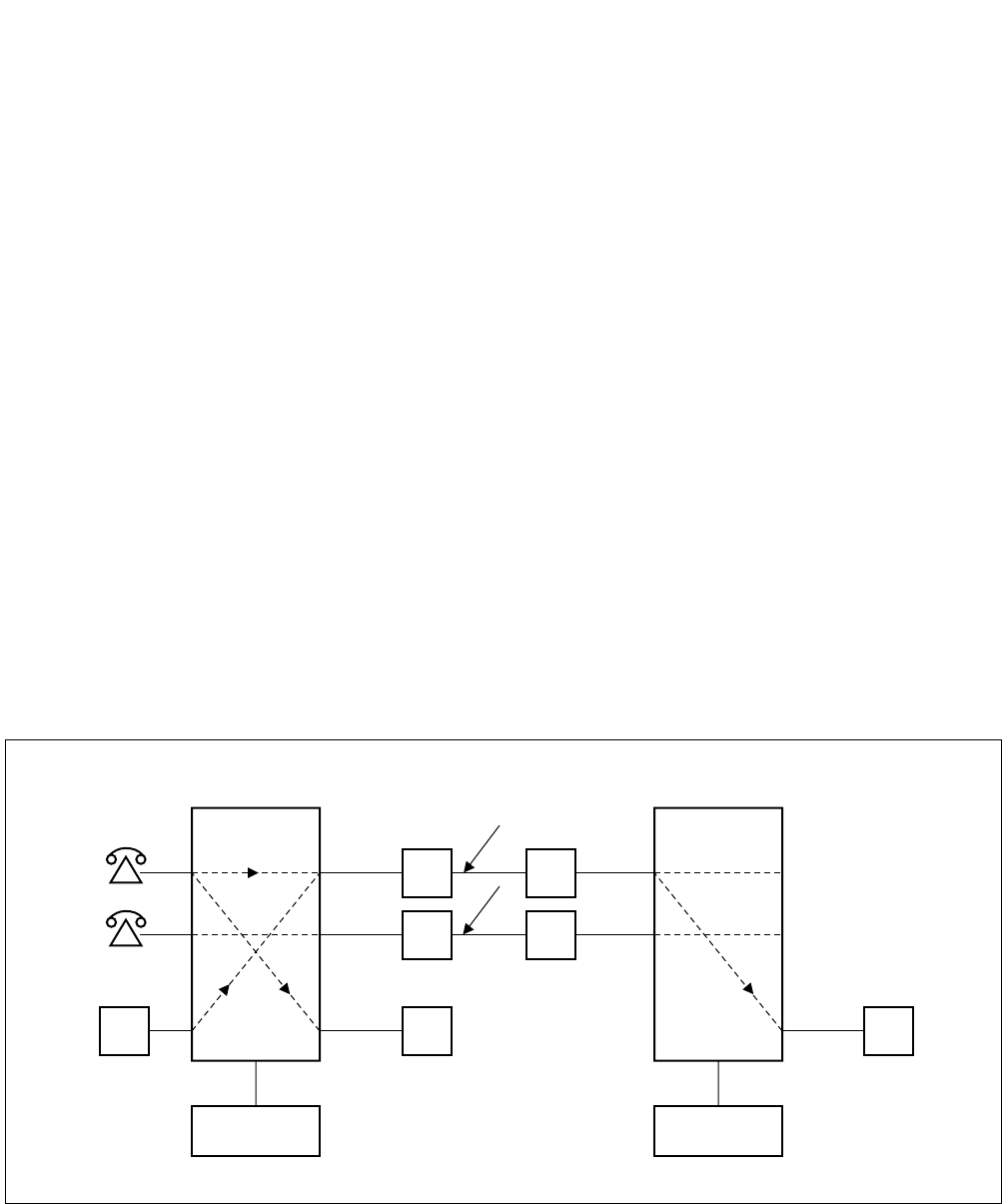
The block diagrams in Figure 2-1 and 2-2 illustrate the difference between Common Channel Interoffice Signalling
(CCIS) and Associated Channel (In-band) Interoffice Signaling (ACIS).
Figure 2-1 Associated Channel (In-Band) Interoffice Signaling
SIGNALING AND VOICE VIA THE SAME LINK
SND REG REG
CONTROL CONTROL
TRUNK TRUNK
ND-71762 (E) CHAPTER 2
Page 3
Issue 2
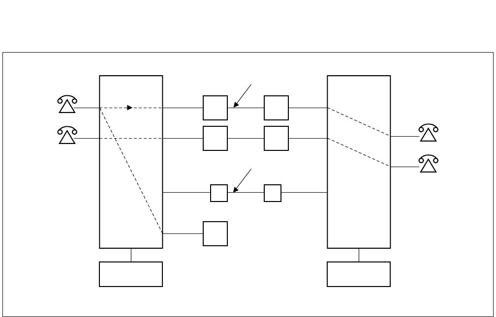
GENERAL INFORMATION FOR CCIS
Figure 2-2 Common Channel Interoffice Signaling
Some advantages of the separate signaling link provided by CCIS are:
(a) Network Transparency
Because CCIS allows data relating to service features and station/trunk status to be exchanged between nodes
at a high rate of speed (64 Kbps), service is provided to all users as though the CCIS network was a single PBX.
(b) Centralized Facilities
Centralized Management: Fault messages from all nodes can be directed to one centralized (management)
node.
Centralized Billing: Billing information for all nodes in the network can be processed at one central
location.
Centralized Attendant Service: It is not necessary in a CCIS network to have an Attendant Console at each
node in the network. Attendant services can be provided to multiple nodes from
one or more central location(s).
(c) Better Utilization of Trunking Facilities
Because network signaling is carried over separate signaling links, more efficient use can be made for network
trunks (reduced call holding time, reduced connection time, etc.). In another word, the number of trunk cir-
cuits, which required to provide a specified traffic capacity, can be reduced.
COMMUNICATION LINK
REG
CONTROL CONTROL
SIGNALING LINK

CHAPTER 2 ND-71762 (E)
Page 4
Issue 2
GENERAL INFORMATION FOR CCIS
(d) Network Reliability
Alternate Routing provides the CCIS network with maximum reliability. If the signaling link between two
nodes should fail, signaling is sent over an alternate route, via another node, without loss of service. Directly-
connected redundant links can also be provided to assure the reliability of the network.
(e) Reduction in Personnel
Because management, cost accounting, and services, such as Attendant operation, can be centralized, the num-
ber of people necessary to administer the network can be reduced.
(f) Reduced Hardware
Signaling over a common channel; better utilization of trunking facilities; and centralized management and
services all result in a vast reduction in hardware when a CCIS network, rather than a conventional Tie line
network, is used.
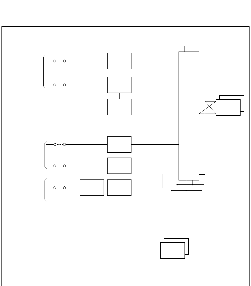
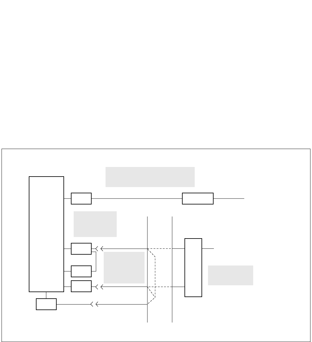
3. SYSTEM CONFIGURATION
3.1 Outline
This Section describes the hardware configuration and its specification, the names of interface equipment and other
related subjects. Figure 2-3 shows No. 7 hardware configuration, respectively. The control signal circuit used for
CCIS is classified into the digital circuit and analog circuit. The CCH card can be used for both digital and analog
control signal circuit and the CCT card is used for digital one. CCH sends control signals to and receives from the
distant office. Also, for network synchronization, PLO/OSC or TSW (Phase Lock Oscillator/Oscillator or Time Di-
vision Switch) are used.
For the analog control signal circuit, CCH circuit card is used with MODEM.
Table 2-1 shows the CCIS interface specifications and their applications.
Table 2-1 CCIS Interface Specifications
TYPE OF
FACILITY
SIGNALING
RATE
INTERFACE
SPECIFICATION
INTERFACE
EQUIPMENT APPLICATION
Voice Frequency
Circuit
4.8 kbps RS-232C, V. 24, V.
28
MODEM V27
or equivalent
Used for a CCIS Tie Line (4ODT) Net-
work.
1.544 Mbps 48-64 kbps T1-D3 T1 Channel Used with T1 (24DTI) lines.
2.048 Mbps 64 kbps E1 E1 Channel Used with E1 (30 DTI) lines.
AT&T IS DDS 56 kbps V. 35,
V. 28/V.11
NEC DCP DSU
or equivalent
Used if network has extensive Tie Lines,
with heavy traffic conditions, and AT&T
IS Digital Data Service is available.
ND-71762 (E) CHAPTER 2
Page 5
Issue 2
GENERAL INFORMATION FOR CCIS
Figure 2-3 Hardware Configuration of No. 7 CCIS System
MDF
<CCIS Digital Line>
<CCIS Analog Line>
CCT
Note 1
Note 1
Note 2
No.7 CCIS
Speech Line
and Signalling
Line
No.7 CCIS
Speech Line
No.7 CCIS
Signalling
Line
DTI
CCH
TRK
TRK
CCHMODEM
Speech
Path
System
PLO
CPU
Note 1: When using one channel of the DTI as the Control Link.
Note 2: When using Analog MODEM as the Control Link.
CHAPTER 2 ND-71762 (E)
Page 6
Issue 2
GENERAL INFORMATION FOR CCIS
4. NETWORK CONFIGURATION
With application of No. 7 CCIS added to the PBX, a network of multiple functions as if it were a single PBX.
Since calls can be freely transferred between one PBX and another, most of the existing station services can be ap-
plied to inter-PBX call connections.
Further, using the CENTRALIZED BILLING-CCIS service and the CENTRALIZED SYSTEM MANAGEMENT
REPORT-CCIS service, billing information and fault information can be processed at one center point instead of
processing at each PBX concerned.
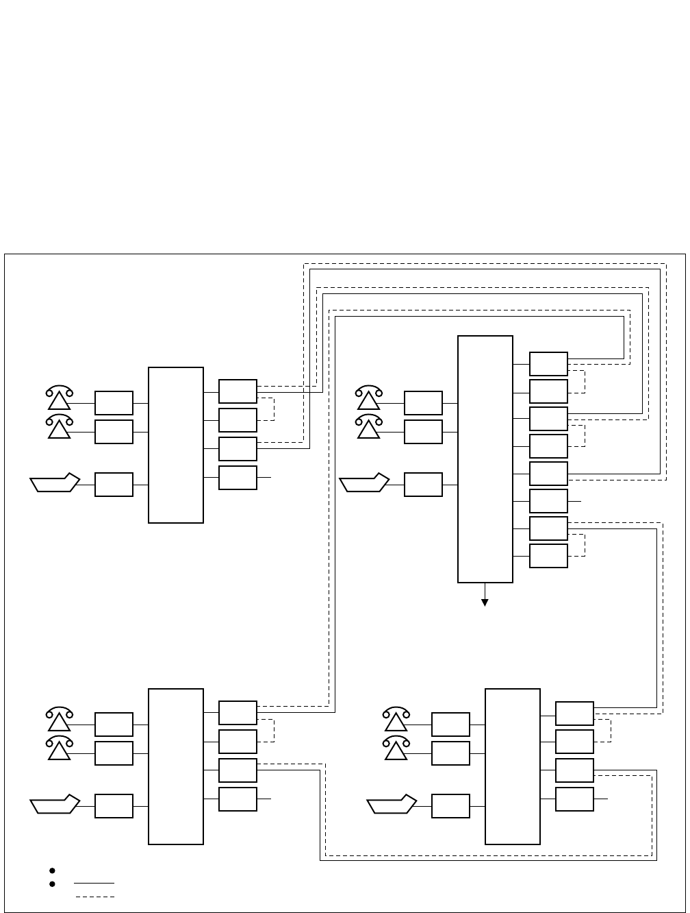
Figure 2-4 shows an example of PBX interoffice network for CCIS Digital Line, and Figure 2-5 shows an example
of network configuration for CCIS Analog Line.
Figure 2-4 Example of Network Configuration for CCIS Digital Line
LC
LC
ATI
PBX DTI
CCH
CCT
COT C.O
LC
LC
ATI
PBX
DTI
CCH
DTI
CCH
CCT
COT
DTI
CCH
C.O
PBXPBX
LC
LC
ATI
DTI
CCH
CCT
COT C.O
LC
LC
ATI
DTI
CCH
CCT
COT C.O
Failure, charging information
One channel of DTI shall be used for signals.
indicates a speech line.
indicates a signal line.
ND-71762 (E) CHAPTER 2
Page 7
Issue 2
GENERAL INFORMATION FOR CCIS
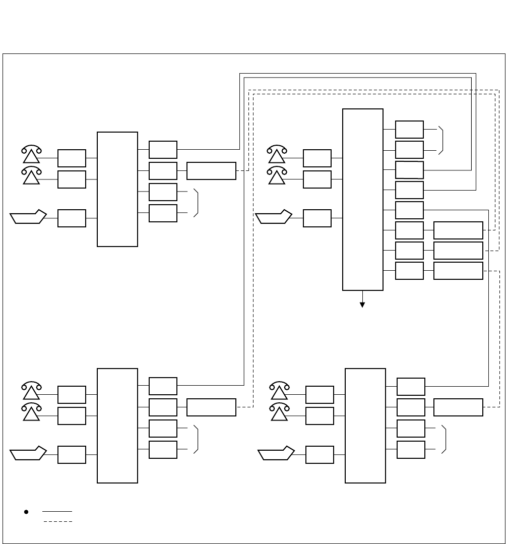
Figure 2-5 Example of Network Configuration for CCIS Analog Line
LC
LC
ATI
CCH
COT
COT
C.O
LC
LC
ATI
PBX
COT
COT
TRK
TRK
TRK
CCH
CCH
PBXPBX
LC
LC
ATI
TRK
COT
COT
C.O
LC
LC
ATI
CCH
COT
COT
C.O
Failure, charging information
indicates a speech line.
indicates a signal line.
TRK
TRK
C.O
CCH
PBX
CCH
MODEM
MODEM
MODEM
MODEM
MODEMMODEM
CHAPTER 2 ND-71762 (E)
Page 8
Issue 2
GENERAL INFORMATION FOR CCIS
4.1 Types of Network
CCIS networks can be divided into the following types, depending upon the numbering plan used:
Main-Satellite Networks
Main-Remote/Campus Networks
Both networks provide uniformity of services throughout the CCIS network, and, because of numbering plan flex-
ibility, station users are not conscious of the distance between nodes.
Main/Satellite Network:
In this type of network, offices are connected by means of a numbering plan consisting of a three-digit office code,
which denotes the location, and four-digit station numbers. An example of a Main/Satellite Network is shown in
Figure 2-6.
Main-Remote/Campus Network:
In these types of networks, offices are connected by means of a numbering plan consisting of four or five digit station
numbers. The first one or two digit(s) of these station numbers are used to denote the location. An example of a
Main-Campus Network is shown in Figure 2-7. Figure 2-8 shows an example of a Main-Remote Network. In this
network, a part of the Main Office is installed as a Remote Office at a nearby site, either within or outside the pre-
mises of the Main Office. An advantage of this network is that it requires far less cabling than would be necessary
if stations were connected to a single PBX. Network numbering specifications are summarized in Table 2-2.
Table 2-2 Network Specifications
TYPE OF
NETWORK: MAIN-SATELLITE NETWORK MAIN-REMOTE/CAMPUS
NETWORK REMARKS
NUMBERING
PLAN:
Office Code: Three digits
Sta. No.:Four digits
Office Code: First one or two digits of
Station Number.
Sta. No.: Max. five digits
ACCESS
METHOD
8-XXX-XXXX XXXXX
NETWORK
SIZE:
Large
(Nationwide)
Small (PBX Premises)/
Medium (Local Area)
Sta. No.
Office Code
Access Code
Sta. No.
Office Code
ND-71762 (E) CHAPTER 2
Page 9
Issue 2
GENERAL INFORMATION FOR CCIS
4.2 Examples of Network Configuration
4.2.1 Main-Satellite Configuration
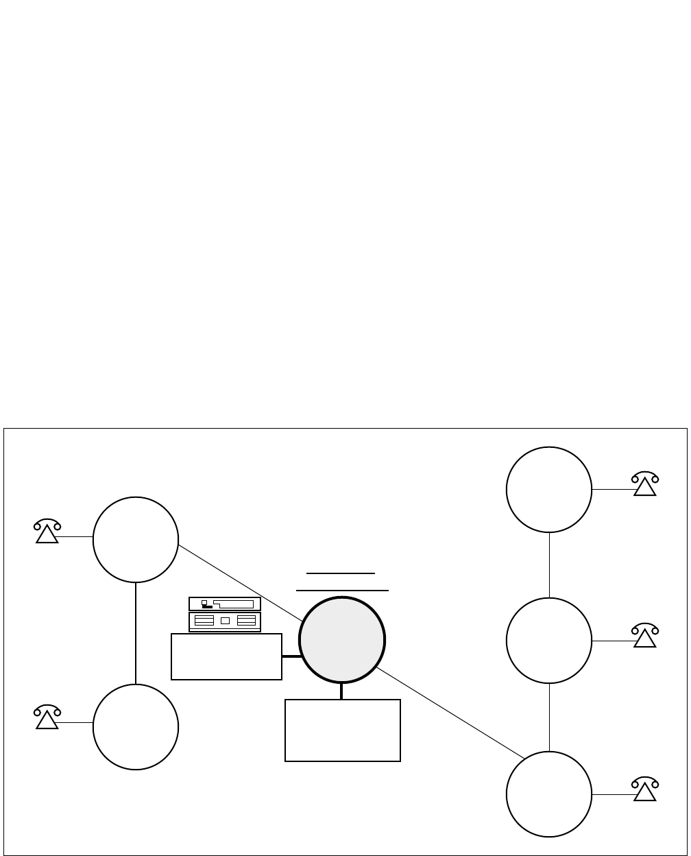
Figure 2-6 shows an example of a Main/Satellite configuration for a nationwide corporate network. This type of net-
work results in cost savings and increased efficiency by providing:
• Leased lines versus toll lines.
• Centralized Attendant Service.
• One central location for call accounting.
• A central MAT (Maintenance Administration Terminal) for network management, control and remote
maintenance.
• Seven-digit on-net numbering.
• Feature transparency.
Figure 2-6 Nationwide Corporation
CITY
E
CITY
D
226-XXXX
225-XXXX
ALL
CONSOLES
227
CITY
F
CITY
A
CITY
B
CITY
C
222-XXXX
223-XXXX
224-XXXX
CORPORATE
HEADQUARTERS
CENTRALIZED
BILLING AND
MANAGEMENT
CHAPTER 2 ND-71762 (E)
Page 10
Issue 2
GENERAL INFORMATION FOR CCIS
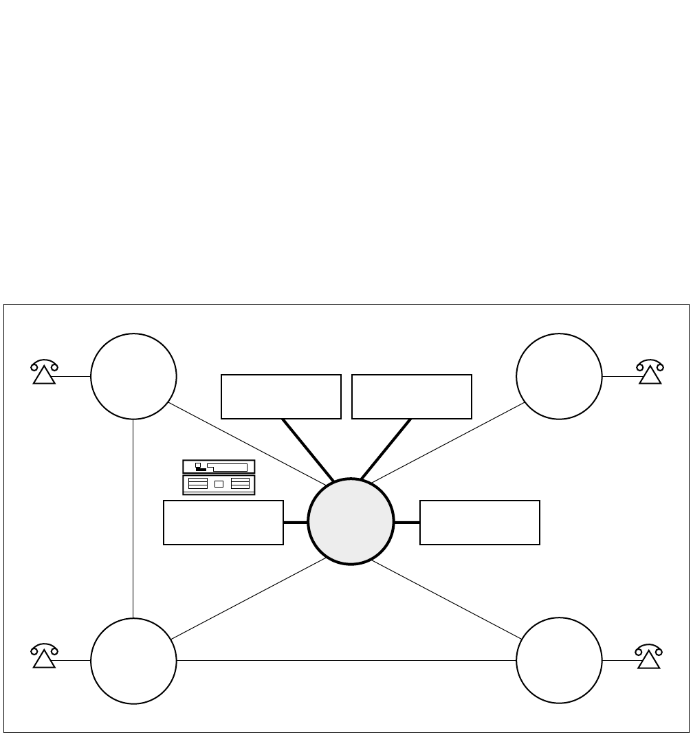
4.2.2 Campus Configuration
Figure 2-7 shows an example of a Campus network. This type of network provides:
• A uniform numbering plan: the first one or two digit(s) of the station number indicate(s) the location. In
this numbering plan, four and/or five-digit station numbering can be used.
• Network access to Common Carrier services.
• Centralized Attendant service and network maintenance.
Figure 2-7 University/Campus Environment
LOCAL
TRUNKS
CENTRALIZED
BILLING
CENTRALIZED
MANAGEMENT
ADMIN.
BLDG.
AND
COMPUTER
CENTER
60XX
63XX
62XXX
61XXX
DORMITORY COMMON
CARRIER LIBRARY
LECTURE
HALL
ND-71762 (E) CHAPTER 2
Page 11
Issue 2
GENERAL INFORMATION FOR CCIS
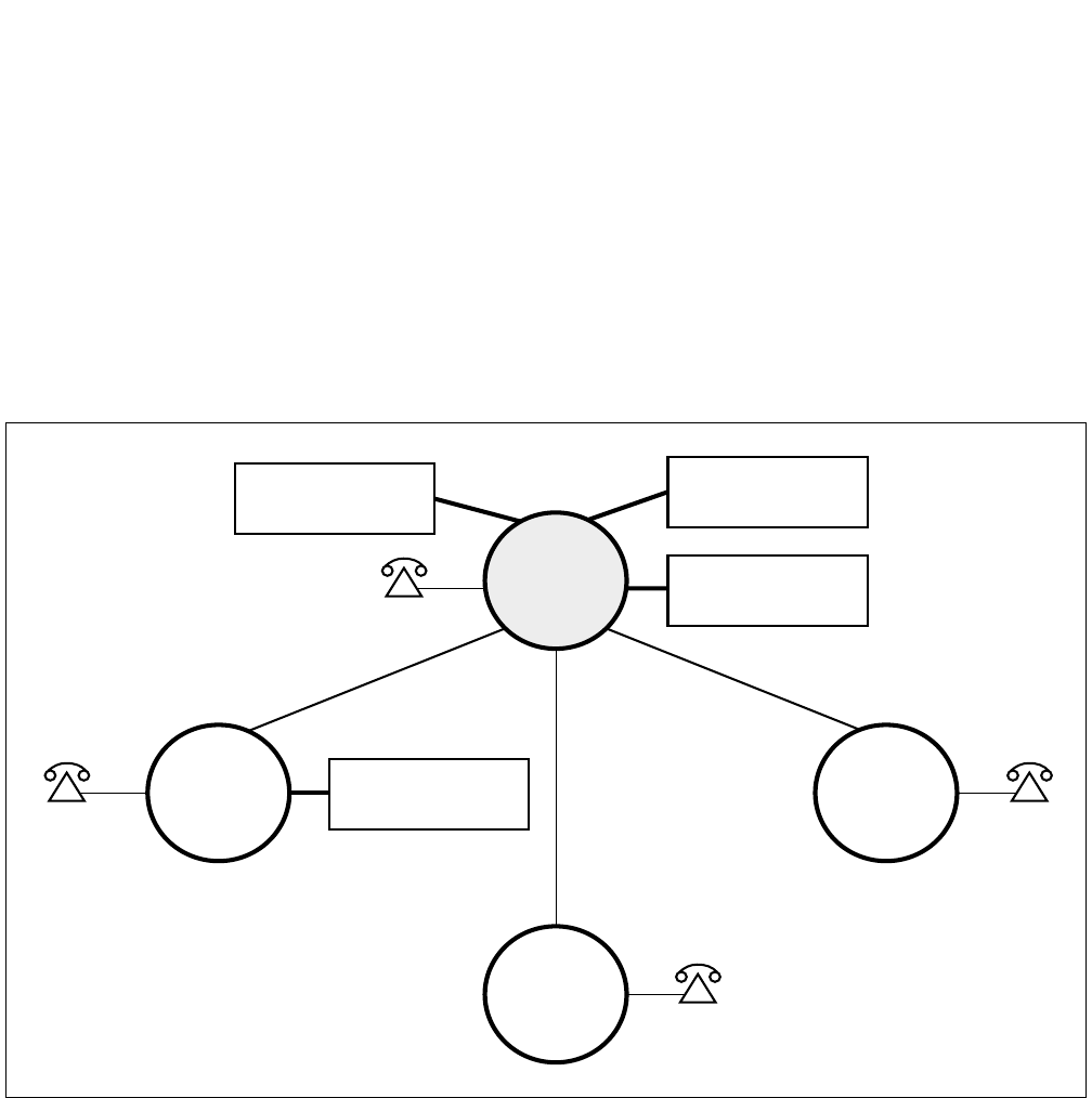
4.2.3 Main-Remote Configuration
Figure 2-8 shows an example of a Main/Remote configuration for a manufacturing/plant environment. This type of
network provides the following advantages:
• A central trunk location for trunking efficiency.
• Centralized management capability.
• Centralized attendant service.
• Centralized billing for inter-departmental accounting.
• Four digit inter-building and intra-city numbering.
• Feature transparency.
• Reduced calling.
Figure 2-8 Manufacturing/Plant Environment
4XXX
5XXX
61XX
60XX
PLANT 1
PLANT 2
TRAINING
CENTER
WAREHOUSE
ALL
TRUNKS
ALL
CONSOLES
3XXX
MAIN
OFFICE
CENTRALIZED
BILLING
CENTRALIZED
MANAGEMENT
CHAPTER 2 ND-71762 (E)
Page 12
Issue 2
GENERAL INFORMATION FOR CCIS
4.3 CCIS Network Modes
The signaling channels of a CCIS network can be connected in one of two ways: Associated Mode or Quasi-Asso-
ciated Mode.
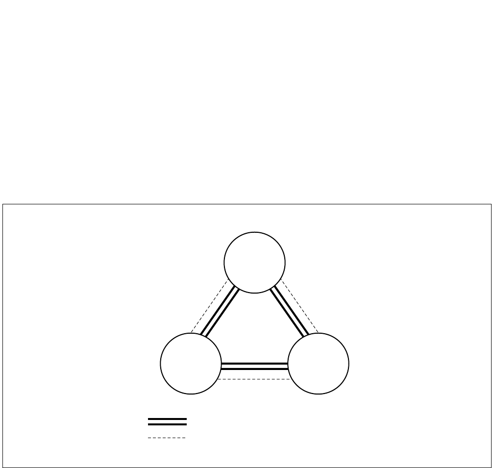
4.3.1 Associated Mode
An Associated Mode network is configured with a signaling channel (data link) between all nodes in the network.
Signaling functions for all inter-node calls are carried over these dedicated signaling channels. In an Associated
Mode Network, if one of the signaling links should fail, signaling can easily be rerouted via another node. An ex-
ample of an Associated Mode network is shown in Figure 2-9 below.
Figure 2-9 Associated Mode Network
NODE
A
NODE
C
NODE
B
Communication Channel
Common Signaling Channel
ND-71762 (E) CHAPTER 2
Page 13
Issue 2
GENERAL INFORMATION FOR CCIS
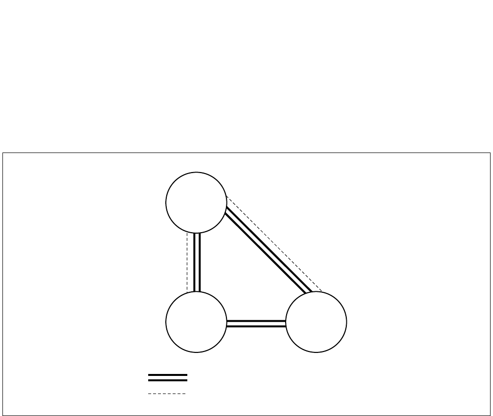
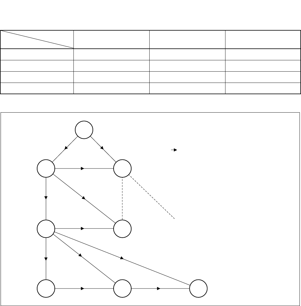
4.3.2 Quasi-Associated Mode
In Figure 2-10 below, nodes A and B, and A and C are connected in the Associated Mode. Nodes B and C are con-
nected in the Quasi-Associated Mode.
In this configuration, signaling data between nodes B and C is routed via node A, while the communication channels
are established directly between nodes B and C. This type of network reduces the hardware necessary to establish
the signaling links.
Figure 2-10 Quasi-Associated Mode Network
4.4 CCIS Network Redundancy
To provide maximum network reliability, two levels of redundancy are provided for the signaling links.
(1) Signaling Channel Redundancy
Redundancy of the inter-node signaling links is provided directly between the nodes by adding one more link
than is necessary for the signaling traffic. This is the N+1 method. If one link fails, signaling is automatically
routed via an alternate link.
(2) Alternate Signaling Path Redundancy
An alternate method of providing network signaling redundancy is to configure the network so that an alternate
path is provided between the nodes.
In the network shown in Figure 2-9, if the signaling link(s) directly connecting nodes B and C should fail, the
signaling would automatically be reconnected via node A without loss of service. (Node A would be designated
as the Signaling Transfer Point [STP]).
Communication Channel
Common Signaling Channel
NODE
A
NODE
B
NODE
C

CHAPTER 2 ND-71762 (E)
Page 14
Issue 2
GENERAL INFORMATION FOR CCIS
5. DIGITAL NETWORK AND NETWORK SYNCHRONIZATION
5.1 Outline
To set up a digital network, it is necessary to establish clock level synchronization among the offices composing the
network.
Among various kinds of synchronizing methods, the PBX is using Receiver synchronization as the standard method.
As for the office ranks, there are the following four kinds:
• Source Office
• Sub-Source Office
• Receiver Office
• Local Receiver Office
Refer to Table 2-3 for synchronization method at network-level.
For types of PBX applicable for each office hierarchy, refer to Table 2-4.
×: Applicable —: Not Applicable
The clock precision is as follows.
M-OSC EXT. OSC High precision - PLO/OSC Subordinate - PLO/TSW
Note 1: M-OSC (Master Oscillator) and EXT. OSC (External Oscillator <for back up>) is not to be furnished by
NEC.
Note 2: High Precision Oscillator - PLO (PH-CK17) / OSC (PA-CK14)
Subordinate Oscillator - PLO (PH-CK16) / TSW (PH-SW10)
For the 1-IMG system, the OSC/TSW card is used in place of PLO.
Table 2-3 Office Ranks and Kind of Oscillator
OSC M-OSC
(Note 2)
EXT. OSC
(Note 1)
PLO/OSC
(High Precision Oscillator)
PLO/TSW
(Subordinate Oscillator) REMARKS
Source Office ×—— —
Sub-Source Office —×× —
Receiver office —— ××
Local Receiver Office —— — ×
OFFICE RANK
>
=
>
=
>
=
ND-71762 (E) CHAPTER 2
Page 15
Issue 2
GENERAL INFORMATION FOR CCIS
×: Applicable —: Not Applicable
Table 2-4 Office Hierarchy and PBX
SYSTEM Single System Dual System REMARKS
Source Office —×
Sub-Source Office —×
Receiver office ××
Local Receiver Office ××
OFFICE RANK
S
SS
R
LR LR LR
R
SS
S: SOURCE OFFICE
SS: SUB-SOURCE OFFICE
R: RECEIVER OFFICE
LR: LOCAL RECEIVER OFFICE
: DIRECTION OF CLOCK SIGNAL
SUPPLY
CHAPTER 2 ND-71762 (E)
Page 16
Issue 2
GENERAL INFORMATION FOR CCIS
5.2 Office Rank
5.2.1 Source Office
The Source Office supplies clock pulses generated by the M-OSC in the self office to the PLO/OSC (High Precision
Oscillator) in the self office.
Figure 2-11 shows the clock supply routes.
Figure 2-11 Clock Supply Routes
M-OSC 0
M-OSC 1
ACT
Change
Clock
Synchronization
Two systems each
ACT
32.768 MHz
8 kHz (FH)
To Switch
System side
PLO 0
(PH-CK17)
/OSC 0
(PA-CK14)
PLO 1
(PH-CK17)
/OSC 1
(PA-CK14)
This figure shows an example of the clock supply routes when the PLO0 is in ACT side.
Note: For 1-IMG system, the OSC (PA-CK14) card is used. For 4-IMG system, PLO (PH-CK17) card is
used.
ND-71762 (E) CHAPTER 2
Page 17
Issue 2
GENERAL INFORMATION FOR CCIS
5.2.2 Sub-Source Office
The Sub-Source Office extracts carrier clocks (24DTI: 1.544 MHz/30DTI: 2.048 MHz) from the DTI opposing to
the Source Office and supplies them to the PLO/OSC (High Precision Oscillator) in the user office.
In preparation for complete clock down from the Source Office, the Sub-Source Office is provided with external
oscillators (EXT. OSC) for backup. Figure 2-12 shows the routes for carrier clock extraction and for backup clocks.
Figure 2-12 Clock Extraction and Backup Routes
External
OSC 0 ACT
Change
CLOCK
Synchronization
Two systems each
ACT
8 kHz (FH)
To Switch
System side
PLO 1
(PH-CK17)
/OSC 1
(PA-CK14)
From DTI
For Backup
Clock receiving route
(max. 4 routes)
PLO 0
(PH-CK17)
/OSC 0
(PA-CK14)
32.768 MHz
External
OSC 1
Note: The OSC (PA-CK14) card is used for the 1-IMG system only.
The PLO (PH-CK17) card is used for the 4-IMG system.
This figure shows an example of the clock supply routes when the PLO0 is in ACT side.

CHAPTER 2 ND-71762 (E)
Page 18
Issue 2
GENERAL INFORMATION FOR CCIS
5.2.3 Receiver Office and Local Receiver Office
For connecting the DTI (Digital Trunk Interface) of the user office to the DTI of a higher-ranking office, the user
office must establish clock synchronization with the higher-ranking office concerned.
A Receiver Office or a Local Receiver Office extracts carrier clocks (24DTI: 1.544 MHz/30DTI: 2.048 MHz) from
the DTI opposing to the higher-ranking office and establishes clock synchronization with the higher-ranking office
by supplying the extracted carrier clocks to the PLO/TSW (Subordinate oscillator) in the user office.
Figure 2-13 shows the routes for clock extraction.
Figure 2-13 Routes for Extracted Clocks
Two systems each
ACT
8 kHz (FH)
To Switch
System side
PLO 1
(PH-CK16)
/TSW 1
(PH-SW10)
From DTI
Clock receiving route
(max. 4 routes)
PLO 0
(PH-CK16)
/TSW 0
(PH-SW10)
32.768 MHz
ACT
Change
CLOCK
Synchronization
This figure shows an example of the clock supply routes when PLO0/TSW0 is in ACT side.
Note: The TSW (PH-SW10) card is used for the 1-IMG system only.
The PLO (PH-CK16) card is used for the 4-IMG system.
ND-71762 (E) CHAPTER 2
Page 19
Issue 2
GENERAL INFORMATION FOR CCIS
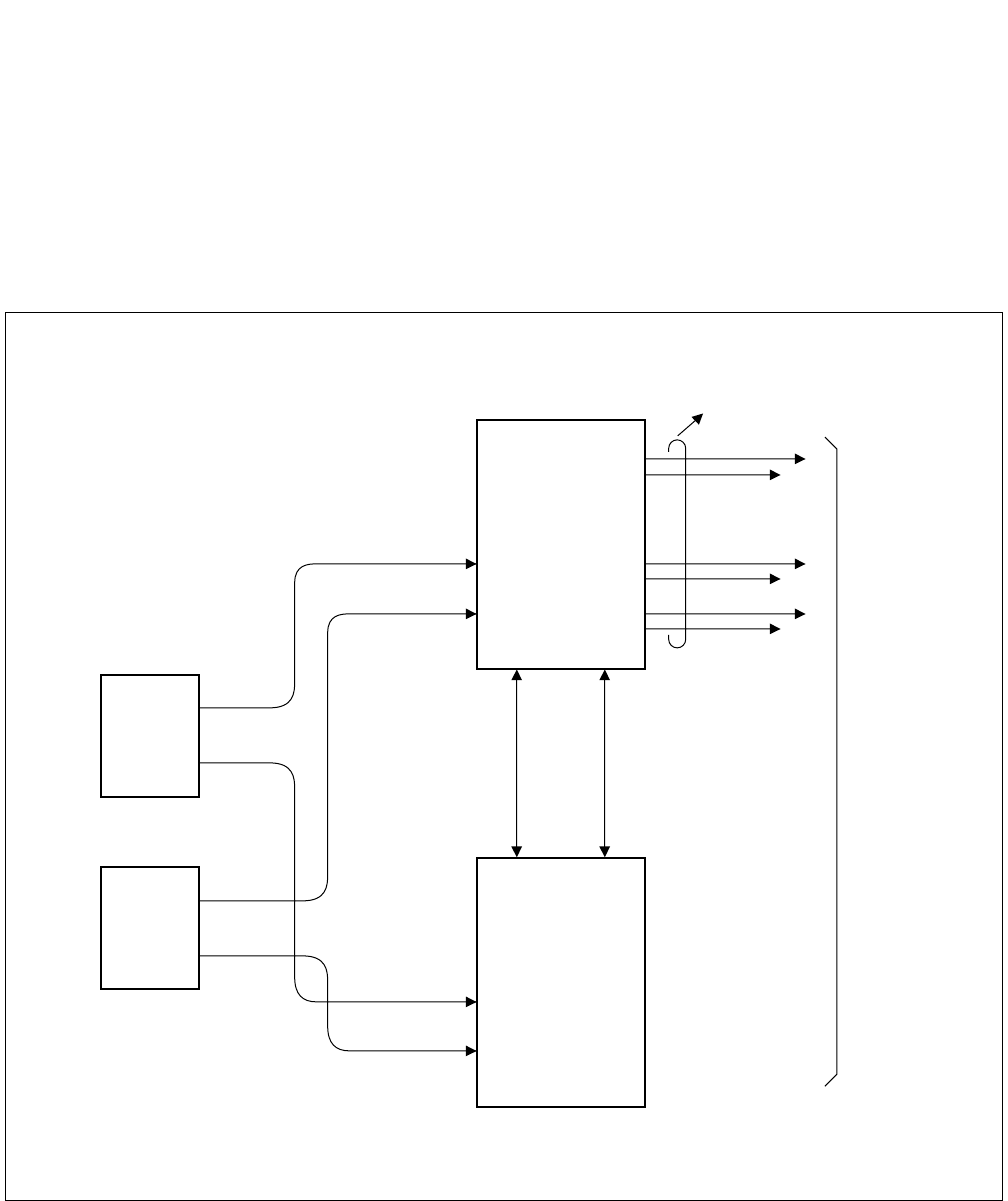
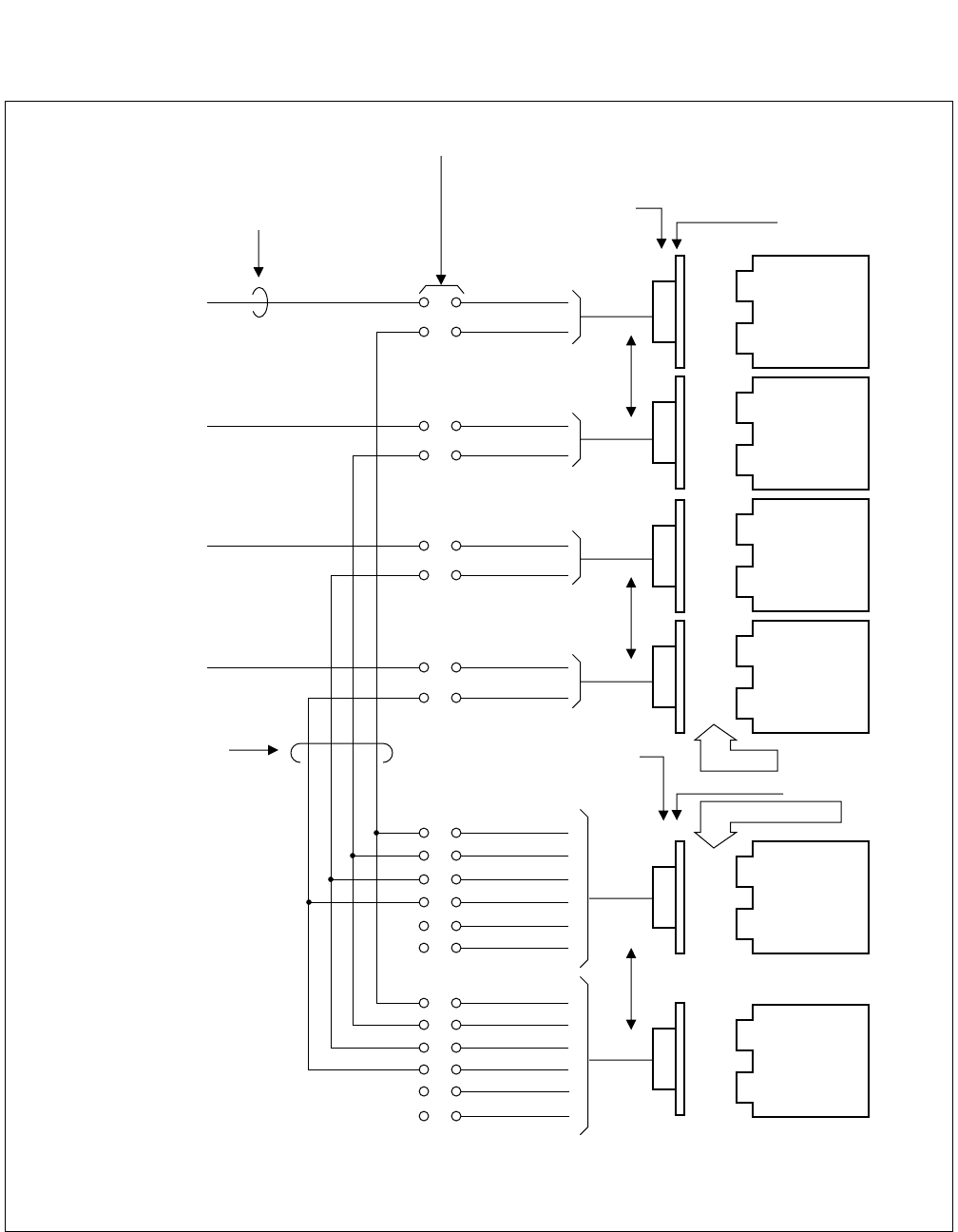
5.3 Clock Pulses from M-OSC/EXT. OSC and Connection with PLO/OSC
Two clock pulses from the M-OSC/EXT. OSC can be supplied to each PLO/OSC.
Figure 2-14 shows the diagram of connection between the M-OSC and the PLO/OSC.
Figure 2-14 Diagram of Connections between M-OSC and PLO/OSC
IDF/MDF for PCM
M-OSC/EXT. OSC
Route 3
Route 2
Route 1
Route 0
M-OSC 1
M-OSC 0
Route 3
Route 2
Route 1
Route 0
M-OSC 1
M-OSC 0
Installation Cable (25p)
0
Backplane wiring
Cross-connection of
PLOs
BWB of TSWM or ISWM/PIM
Cable-connection
Multiple-connection of
DTIs
PLO 1
(PH-CK17)
/OSC 1
(PA-CK14)
PLO 0
(PH-CK17)
/OSC 0
(PA-CK14)
1
Note: The OSC (PA-CK14) card is used for the 1-IMG system only.
The PLO (PH-CK17) card is used for the 4-IMG system.

CHAPTER 2 ND-71762 (E)
Page 20
Issue 2
GENERAL INFORMATION FOR CCIS
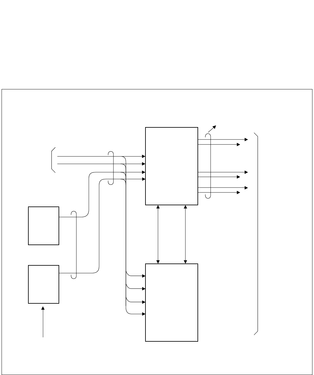
5.4 Clocks Extracted from DTI and Connection of PLO/TSW
Extracted clocks for a maximum four routes can be supplied to the PLO/TSW. The priority among the four routes
is Route 0, 1, 2, and 3 in an ascending order.
To supply extracted clocks to the PLO/TSW, the Champ-connector cable extending from the DTI and the Champ-
connector cable extending from the PLO/TSW are brought into the IDF/MDF for the PCM, where they are to be
connected with each other.
Figure 2-15 shows the diagram of connections between the PLO/TSW and the DTI.
ND-71762 (E) CHAPTER 2
Page 21
Issue 2
GENERAL INFORMATION FOR CCIS
Figure 2-15 Diagram of Connections between PLO/TSW and DTI
In-House Cable for PCM
End-end grounding
(Shielded cable)
PCM
IDF/MDF for PCM
Champ Connector
(LT Connector) BWB
DTI 3
DTI 2
DTI 1
DTI 0
Installation cable (25p)
Installation cable (25p)
Champ Connector
Cross- Connection
wires PIM
PIM/TSWM/ISWM
BWB
PLO 1
(PH-CK16)
/TSW
(PH-SW10)
PLO 0
(PH-CK16)
/TSW
(PH-SW10)
Route 3
Route 2
Route 1
Route 0
M-OSC 1
M-OSC 0
Route 3
Route 2
Route 1
Route 0
M-OSC 1
M-OSC 0
Installation cable (25p)
Note: The TSW (PH-SW10) card is used for the 1-IMG system only.
The PLO (PH-CK16) card is used for the 4-IMG system.
CHAPTER 2 ND-71762 (E)
Page 22
Issue 2
GENERAL INFORMATION FOR CCIS
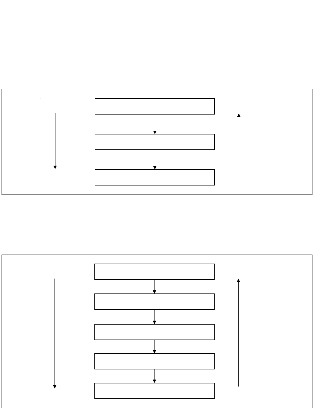
5.5 Automatic Clock Route Changeover
5.5.1 Automatic Route Changeover on Fault to M-OSC/EXT. OSC of Input Clock Route
Priority order for automatic route changeover on fault occurrence to the M-OSC/EXT. OSC which are supplying
clocks is shown in Figure 2-16.
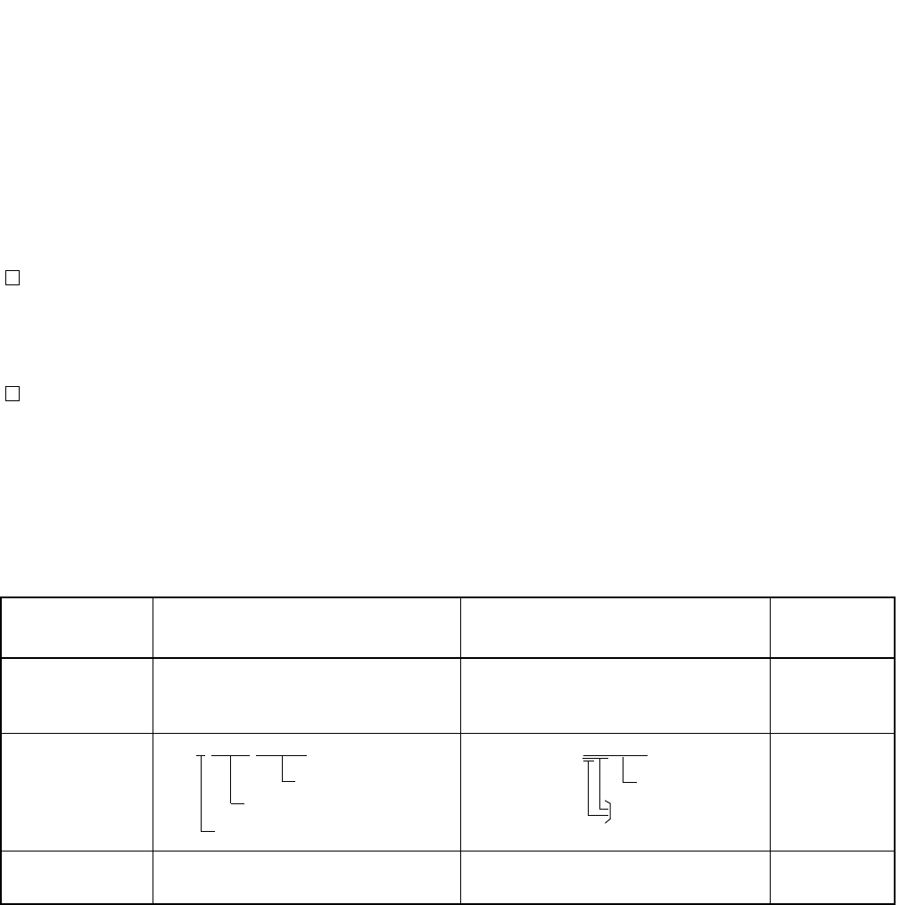
Figure 2-16 Route Automatic Changeover Priority Order (DCS connection)
5.5.2 Automatic Route Changeover on Fault to DTI of Input Clock Route
Priority order for automatic route changeover on fault occurrence to the DTI which is extracting clocks is shown in
Figure 2-17.
Figure 2-17 Route Automatic Changeover Priority Order (DTI connection)
M-OSC/EXT.OSC 0
M-OSC/EXT.OSC 1
PLO/OSC Self Running
High
Low
Priority order
Changeover
sequence
Route 0
Route 1
Route 2
Route 3
PLO/TSW Self Running
High
Low
Priority order
Changeover
sequence

ND-71762 (E) CHAPTER 2
Page 23
Issue 2
GENERAL INFORMATION FOR CCIS
Table 2-5 shows the algorithm for changeover of input clocks from the DTI. The Table shows how the PLO selects
a specific route for input clocks according to the input clock status of four routes, thus establishing clock synchro-
nization. For example, in a case where Route 1, which has been selected due to a fault occurrence to clock input
Route 0, has also become faulty, Table 2-5 should be looked up as follows:
STEP 1: Look at Route 1 block under “Selected Route Before changeover” (the current input clock route) column.
STEP 2: Under “Each Route Input Clock Status” column, look for the block which shows that only Routes 0 and
1 are faulty.
STEP 3: Under “Route To Be Selected After Changeover” column located at the right extremity of the Table,
Route 2 is indicated in the block corresponding to the block found in Step 2.
If a route of which priority order is higher than the current route has been restored to normal, the route is changed
over to that specific route.

CHAPTER 2 ND-71762 (E)
Page 24
Issue 2
GENERAL INFORMATION FOR CCIS
Note: Priority order is Route 0, 1, 2, and 3 in an ascending order.
×:Normal
— : Fault (Clock Down, etc.)
* : Normal or Faulty
• When power for the PLO/TSW is turned on, Route 0 is selected.
Table 2-5 Algorithm of Changeover of Input Clocks from DTI
SELECTED
ROUTE BEFORE
CHANGEOVER
EACH ROUTE INPUT CLOCK STATUS (Note) ROUTE TO BE
SELECTED AFTER
CHANGEOVER
REMARKS
ROUTE 0 ROUTE 1 ROUTE 2 ROUTE 3
Route 0
—×** Route 1
—— ×*Route 2
——— ×Route 3
— — — — PLO/TSW Self Running
Route 1
×*** Route 0
—— ×*Route 2
——— ×Route 3
— — — — PLO/TSW Self Running
Route 2
×*** Route 0
—×** Route 1
——— ×Route 3
— — — — PLO/TSW Self Running
Route 3
×*** Route 0
—×** Route 1
—— ×*Route 2
— — — — PLO/TSW Self Running
ND-71762 (E) CHAPTER 2
Page 25
Issue 2
GENERAL INFORMATION FOR CCIS
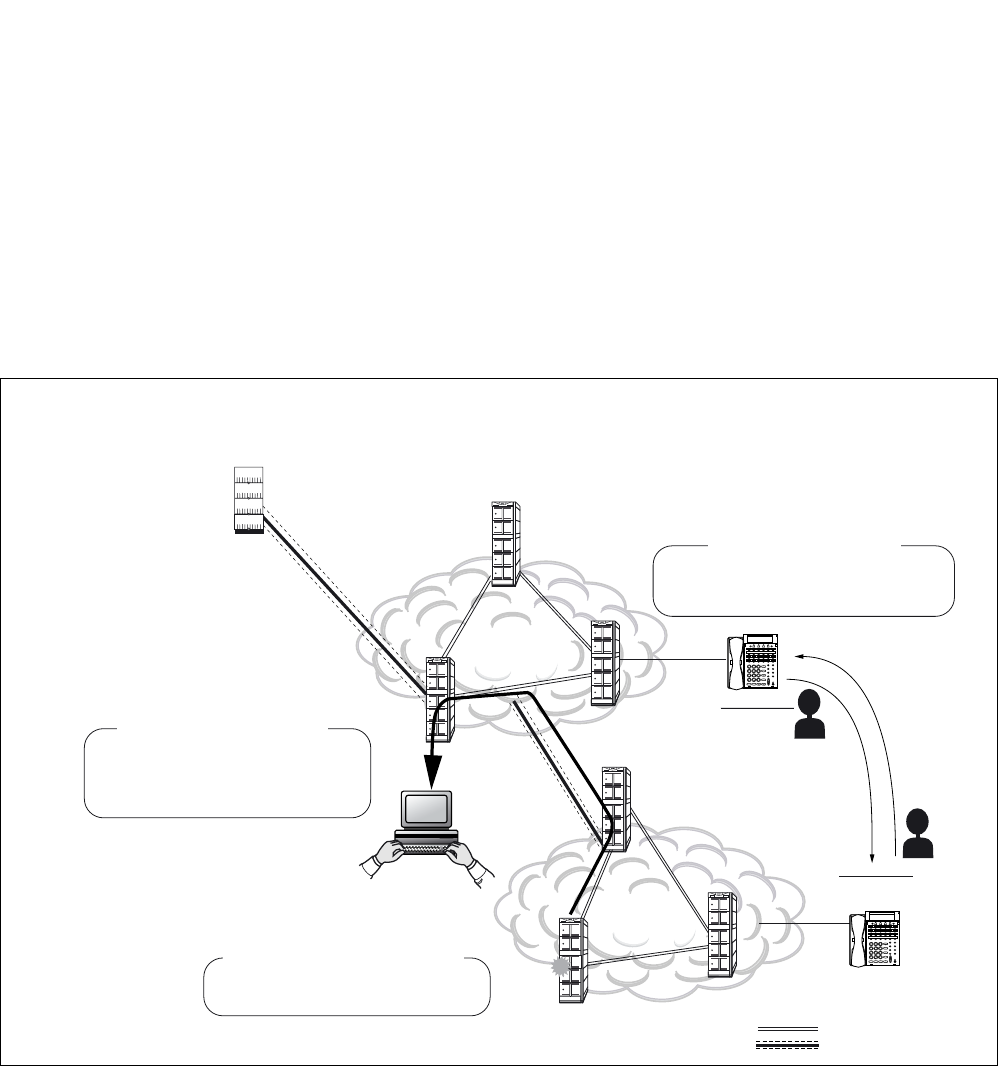
6. NETWORK THROUGH FCCS GROUPS AND NEAX2000 IPS Internet Protocol Server
6.1 Network Configuration
The network through multiple FCCS Networks (FCCS Groups) and NEAX2000 IPS Internet Protocol Server system
can be realized to manage the telephone number data in those systems altogether and to centralize functions in the
network.
* FCCS Group: network where multiple NEAX2400 IPXs are connected via FCCS link.
* In this section, NEAX 2400 IPX system is described as IPX and NEAX2000 IPS Internet Protocol Server system
is described as IPS.
Node G
200000
390000
390000
200000
IPS
Centralized MAT
... ... ... ... ...
... ... ... ... ...
... ... ... ... ...
... ... ... ... ...
: CCIS
: FCCS
:
:
;:;;::;: ;:;::;::;:
Node A
;:;;::;: ;:;::;::;:
Node C
Node D
Node E
FCCS Network
FCCS Network
Node F
...
...
...
...
...
...
... ...
...
...
...
...
...
...
...
... ...
...
...
...
...
...
...
...
... ...
...
...
...
...
...
...
...
... ...
...
IPXs in FCCS Groups and IPS can
be managed via Centralized MAT.
Centralized Maintenance - CCIS
-ment Report-CCIS
Alarm information occurred at IPXs
in FCCS Groups and IPS can be
collected via Centralized MAT.
Centralized System Manage
;:;;::;: ;:;::;::;:
;:;;::;: ;:;::;::;:
;:;;::;: ;:;::;::;:
;:;;::;: ;:;::;::;:
Node B
This figure shows an example of centralized functions activation.
Telephone Number data can be carried
to the remote FCCS Network via simple
command operation.
Number Portability - CCIS
ALARM

CHAPTER 2 ND-71762 (E)
Page 26
Issue 2
GENERAL INFORMATION FOR CCIS
1. The following table shows the network type classification.
IPX: NEAX 2400 IPX IPS: NEAX 2000 IPS Internet Protocol Server
For these network types, the following services are realized or enhanced.
Number Portability - CCIS [N-46]
Centralized Maintenance - CCIS [C-167]
Centralized Billing - CCIS [C-55]
Centralized System Management Report - CCIS [C-57]
Message Center Interface - CCIS [C-67]
For availability of the other services in this network, see “Feature and Specifications Manual”.
2. There are two connection types for the network.
a.) IPS - IPX connection
b.) IPX - IPX connection
6.2 Conditions for Network Establishment
•IPS - IPX
1. Additional IPS cannot be connected to IPS that has already been connected with IPX. (Only one SPAN is
allowed for IPX-IPS connection.)
2. A maximum number of routes and that of nodes for the IPS system are given by subtracting the number of
routes (LGRT) used for the IPX system from 899 (maximum number of routes in an FCCS group).
Note: This condition is applied to the IPX side. The IPS system may accommodate up to 255 nodes (including IPX)
because the maximum number of Point Codes (PCs) assigned at IPS system is 255.
3. When a signal route is deleted, another signal route can be shared with multiple routes (the voice route is
required per route). However, when the network is established using EVENT BASED-CCIS (For details,
ISDN System Data Design Manual), the signal route is required per route.
•IPX - IPX
1. The maximum number of nodes per FCCS group is 253.
2. The maximum number of routes assigned in each FCCS group is 899.
3. An individual NCN and NDM exist in each FCCS group.
TYPE
CONNECTION TYPE A MAXIMUM
NUMBER OF
TELEPHONE
NUMBER
SERVICE
IPX - IPX IPS - IPX IPX - IPX IPS - IPX
1 FCCS CCIS 120,000 FCCS service CCIS service
2 CCIS CCIS 120,000 CCIS service CCIS service
ND-71762 (E) CHAPTER 2
Page 27
Issue 2
GENERAL INFORMATION FOR CCIS
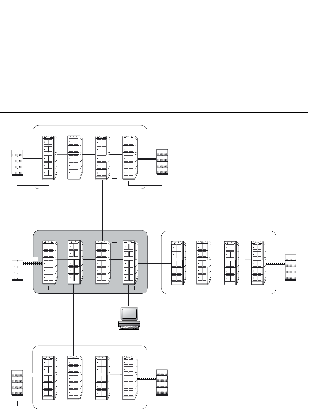
6.3 FCCS Group (FUG)
1. Since multiple FCCS networks are connected in the network, FCCS network group number is required to
distinguish each FCCS network from others. An FCCS network group is called FCCS group (FUG), and a
maximum of 4 FUGs can be connected in the network.
2. A center FUG should be specified from among multiple FUGs in the network. It is the sole node allowed
assigning and deleting telephone numbers within the self FUG and the others.
3. The network consists of FUGs and NEAX2000IPS systems within the range of 2 SPANs from the center
FUG and within the range of 4 SPANs from end to end.
NETWORK CONFIGURATION
Centralized MAT
;:;;::;: ;:;::;::;:
;:;;::;: ;:;::;::;:
;:;;::;: ;:;::;::;:
;:;;::;: ;:;::;::;:
IPX IPX IPX IPX
;:;;::;: ;:;::;::;:
;:;;::;: ;:;::;::;:
;:;;::;: ;:;::;::;:
;:;;::;: ;:;::;::;:
IPX IPX
IPX
IPX
CCIS
;:;;::;: ;:;::;::;:
;:;;::;: ;:;::;::;:
;:;;::;: ;:;::;::;:
;:;;::;: ;:;::;::;:
IPX
IPX
IPX IPX
CCIS
;:;;::;: ;:;::;::;:
;:;;::;: ;:;::;::;:
;:;;::;: ;:;::;::;:
;:;;::;: ;:;::;::;:
IPX IPX IPX IPX
FUG4
2SPAN
FUG2 (Center FUG)
FUG3
FUG1
2SPAN
1SPAN
1SPAN 1SPAN
2SPAN2SPAN
2SPAN
1SPAN
CCIS
CCIS
CCIS
CCIS
CCIS

CHAPTER 2 ND-71762 (E)
Page 28
Issue 2
GENERAL INFORMATION FOR CCIS
6.4 Interactions
1. PS Roaming and Hand-over services cannot be activated in the network. To execute Roaming service, the
Q.931a line should be connected exclusively.
2. The OAI/ACD service in the network is executed on the same condition in the normal CCIS network.
3. ISDN transmitting information (16-digit caller number service. Attribute information notification service
(BC, LLC, HLC) and Calling sub-address transfer service) assigned by ARTD, CDN98: CI = 1 can be
transmitted for the IPX to IPX connection only.
4. Broad Band (N × 64kbps tranfer rate) is available for the IPX to IPX connection only.
5. ATTENDANT CONSOLE [A-3] (see Feature Programming Manual) service is available only if the atten-
dant console in the IPX is used.

ND-71762 (E) CHAPTER 3
Page 29
Issue 2
SWITCH SETTING SHEETS
CHAPTER 3 SWITCH SETTING SHEETS
1. GENERAL
This chapter shows switch setting on the individual circuit cards used in the basic CCIS network (not including cir-
cuit cards related to Network through FCCS Groups and NEAX2000 IPS). These sheets are used when setting the
switches on the circuit cards during system installation.
The contents of the Switch Setting for each circuit card contains of the following information.
• Mounting slot(s) in the related Module
• Location of switches and switch setting positions
• Note(s) pertaining to switch positions
2. LIST OF CIRCUIT CARDS
Table 3-1 is the list of Circuit Cards required for CCIS features.
Please refer to “Circuit Card Manual” for more information.
Table 3-1 List of Circuit Cards for CCIS
SYMBOL CIRCUIT CARD REMARKS
CCH PA-2CCHA For Digital/Analog CCIS Line
CCT PA-24CCTA For Digital CCIS Line (1.544 Mb/s)
PA-30CCTB For Digital CCIS Line (2.048 Mb/s)
DTI PA-DTA/PA-24DTR For Digital CCIS Line (1.544 Mb/s)
PA-30DTS For Digital CCIS Line (2.048 Mb/s)
OSC PA-CK14 Oscillator (High precision oscillator for the 1-IMG system)
TSW PH-SW10 Time Division Switch
(Subordinate oscillator for the 1-IMG system)
PLO PH-CK16 Subordinate Oscillator (for the 4-IMG system)
PH-CK17 High Precision Oscillator (for the 4-IMG system)
CHAPTER 4 ND-71762 (E)
Page 30
Issue 2
INSTALLATION PROCEDURE
CHAPTER 4 INSTALLATION PROCEDURE
1. GENERAL
This chapter explains the installation procedure for connecting the PBX and the CCIS line. The scope of the instal-
lation procedure explained in this manual is shown in Figure 4-1. For procedures not explained in this manual, refer
to the Installation Manual:
2. PRECAUTIONS ON INSTALLATION
This manual provides “Static Caution” indicators (Figure 4-2) on pages where work involving static-sensitive com-
ponents is described.
Figure 4-1 Scope of the Installation Procedure
PBX
CCH MODEM
MDF/IDF
DTI
CCH
PLO
DSU CCIS LINE
(DIGITAL LINE)
CCIS LINE
(ANALOG LINE)
CCT
Setting of Switch
Positions on the
Circuit Cards
(See Section 3.2)
Front Cable
Connection
between the
DTI and CCH
(See Section 3.4)
Cable Running from PBX
to the MODEM for Analog CCIS Line
(See Section 3.5)
Cross Connection
from MDF to DSU
(See Section 3.3)
ND-71762 (E) CHAPTER 4
Page 31
Issue 2
INSTALLATION PROCEDURE
Figure 4-2 Static Caution Indication
The 3M Model 8012 Portable Field Service Kit (Figure 4-3) is recommended as an effective countermeasure against
static electricity. The kit is available from NEC.
Figure 4-3 3M Model 8012 PORTABLE FIELD SERVICE KIT
Wrist Strap
Place the Circuit
Card on a
conductive sheet.
Connect ground wire to the Earth
terminal of the Module Group.
CHAPTER 4 ND-71762 (E)
Page 32
Issue 2
INSTALLATION PROCEDURE
3. INSTALLATION PROCEDURE
3.1 General Flow of Installation Procedure
This section describes installation procedure divided into installation procedure items shown in Figure 4-1. The
work flow and the reference paragraphs are shown below.
• For Digital CCIS Line
• For Analog CCIS Line
START
Setting of switch positions and
mounting of the circuit cards.
Refer to paragraph 3.2: “Setting of Switch Positions and
Mounting of the Circuit Cards”.
Cable running from the PBX to the
MDF.
Refer to “Cable Running from the PBX to MDF,
ATTCON, MAT, and SMDR” of the Installation
Manual.
Cable termination and cross
connection from the MDF to the DSU.
Refer to paragraph 3.3: “Cable Termination and Cross
Connection from the MDF to the DSU”.
Front cable connection between DTI
and CCH.
Refer to Figure 4-12 “Front Cable Connections between
DTI/CCT and CCH”.
END
START
Setting of switch positions and
mounting of the CCH card.
Refer to paragraph 3.2: “Setting of Switch Positions and
Mounting of the Circuit Cards”.
Cable Running from the PBX to the
MODEM for Analog CCIS Line.
Refer to paragraph 3.5: “Cable Running from PBX to
the MODEM for Analog CCIS Line”.
END
ND-71762 (E) CHAPTER 4
Page 33
Issue 2
INSTALLATION PROCEDURE
3.2 Setting of Switch Positions and Mounting of the Circuit Cards
The setting of switch positions and mounting of circuit cards should be performed according to the flowchart below.
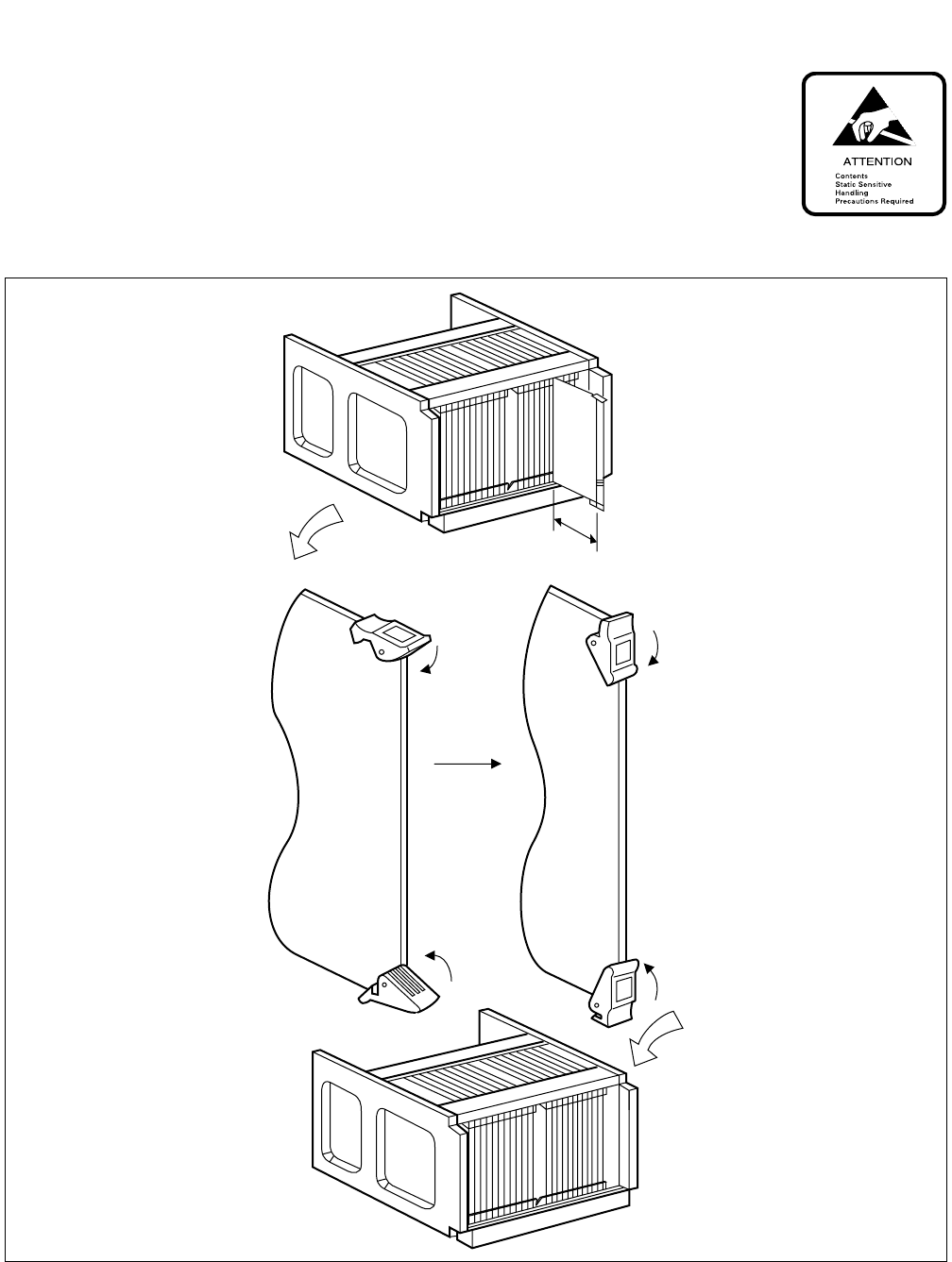
START
Unpack the circuit cards. Unpack each circuit card and remove it from the
polyethylene bag.
Clean the connector portion of the
circuit cards.
Wipe the connector portion clean using a soft cloth
moistened with pure trichloroethylene or methanol
(medical alcohol). Make sure that no lint or dust
remains on the connector after cleaning.
Circuit cards which are already mounted should be
extracted and cleaned as per the above instructions.
Confirm the mounting positions of the
circuit cards.
Confirm the mounting position of each circuit card by
referring to the Module Face Layout of the Circuit Card
Manual.
Confirm that the color code of the card puller tab
coincides with that of the card mounting slot.
Confirm the slot number on the module. Slot numbers
are indicated at the top of each module, and range from
00 to 23.
Perform switch setting. Set the required switches according to the Switch
Setting Sheets in CHAPTER 3.
Mount the circuit cards. After the switches have been set, insert the card in the
module. Refer to Figure 4-4.
END
CHAPTER 4 ND-71762 (E)
Page 34
Issue 2
INSTALLATION PROCEDURE
Figure 4-4 Circuit Card Mounting (Partial Insertion)
About 50 mm
(2 inches)

ND-71762 (E) CHAPTER 4
Page 35
Issue 2
INSTALLATION PROCEDURE
3.3 Cable Termination and Cross Connection from the MDF to the DSU
Cable termination and cross connection from the MDF to the DSU should be performed according to the flowchart
below:
Note: Provide the necessary cross connections at the MDF by using copper of 0.5 mm diameter (24AWG). Dual
core twisted wire is used for speech path, and single-core wire is used for control. It is recommended that
wires of different colors be used for trunks, station lines, etc., so that they can easily be distinguished.
Note: For the 1-IMG system: the Phase Lock Oscillator function equipped with TSW card can be used for Digital
Interface, and while the OSC (PA-CK14) card is used when the system requires a high precision oscillator.
START
Check terminal location on
the PBX side of the MDF
24DTI/30DTI Card
24CCT/30CCT Card
Referring to Figure 4-5, identify the
lead names for those cards and the
terminal location of the leads.
PLO/TSW Card Referring to Figure 4-6 through 4-7,
identify the lead names for the PLO/
TSW (Note) card and the terminal
location of the leads.
Cross Connection When accepting sync.
clocks from External
High-Stability
Oscillator
Referring to Figure 4-8 or Figure 4-9,
provide the necessary cross
connections.
When accepting sync.
clocks from other
office (master or sub-
master office)
Referring to Figure 4-10 or Figure 4-
11, provide the necessary cross
connections.
END
CHAPTER 4 ND-71762 (E)
Page 36
Issue 2
INSTALLATION PROCEDURE
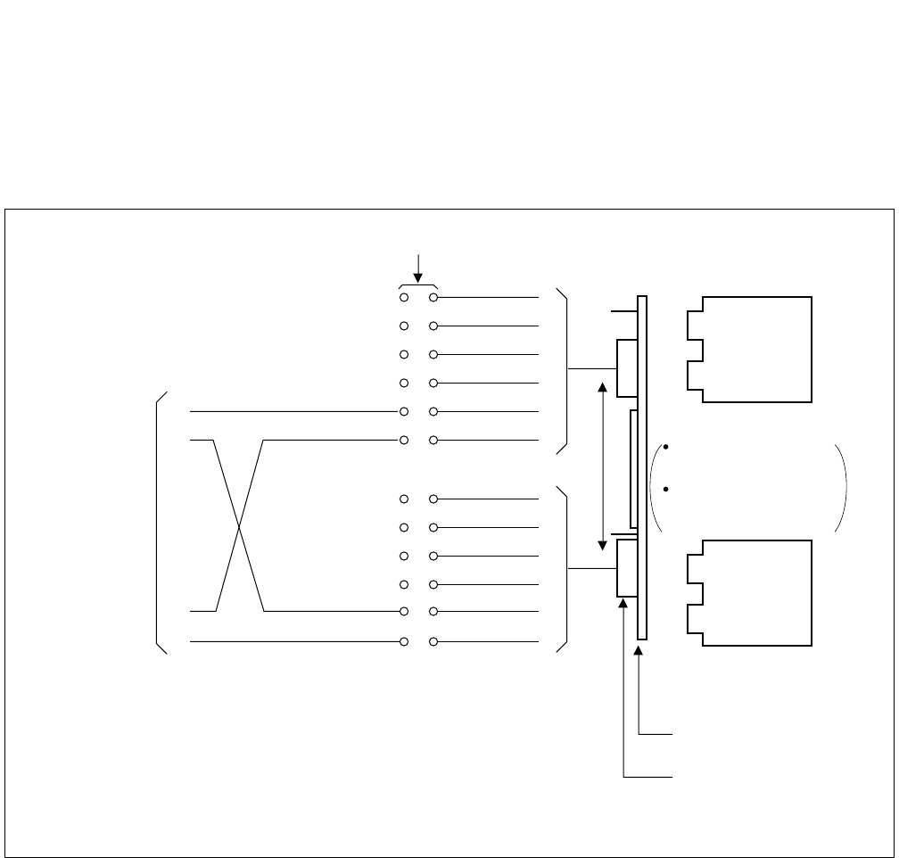
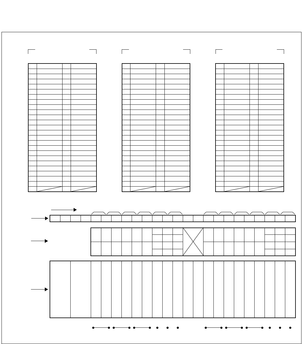
Figure 4-5 LT Connector Leads Accommodation for DTI/CCT
1
Highway Block
26 1
27 E 2 E
28 3
29 RB 4 RA
41 16
40 15
39 14
38 13
37 12
36 11
33 TB 8 TA
32 7
31 6
30 POUTB 5 POUTA
35 10
34 9
48 23
47 22
46 21
44 19
45 20
43 18
42 17
49 24
50 25
LT1, 5, 7, 11 Connector
Accommodated in *1
26 1
27 2
28 3
29 4
41 TB 16 TA
40 15
39 14
38 POUTB 13 POUTA
37 RB 12 RA
36 11
33 8
32 7
31 6
30 5
35 E 10 E
34 9
48 23
47 22
46 21
44 19
45 20
43 18
42 17
49 24
50 25
LT2, 4, 8, 10 Connector
Accommodated in *2
26 1
27 2
28 3
29 4
41 16
40 15
39 14
38 13
37 12
36 11
33 8
32 7
31 6
30 5
35 10
34 9
48 23
47 22
46 POUTB 21 POUTA
44 19
45 RB 20 RA
43 E 18 E
42 17
49 TB 24 TA
50 25
LT3, 5, 9, 11 Connector
Accommodated in *3
02 03 04 05 06 07 08 09 10 11 12 13 14 15 16 17 18 19 2000 01 21 22 23
01 03 05 07 09 11 14 18
23 07 15 19 23
22
06
14 18 22
00 02 04 06 08 10 12 16
21
09 11
13 17 21
20 08 10 12 16 20
*3
*2
*3
*1
*1
*2
*3
*1
*2
*3
0 2345 67891011
LT0 LT1 LT2 LT3 LT4 LT5 LT8 LT9 LT10 LT11
LT Connector Name
Slot No.
Group No.
PIM
13 17
15 19 01
00
03
02
05
04
LT6 LT7
*2
*1
ND-71762 (E) CHAPTER 4
Page 37
Issue 2
INSTALLATION PROCEDURE
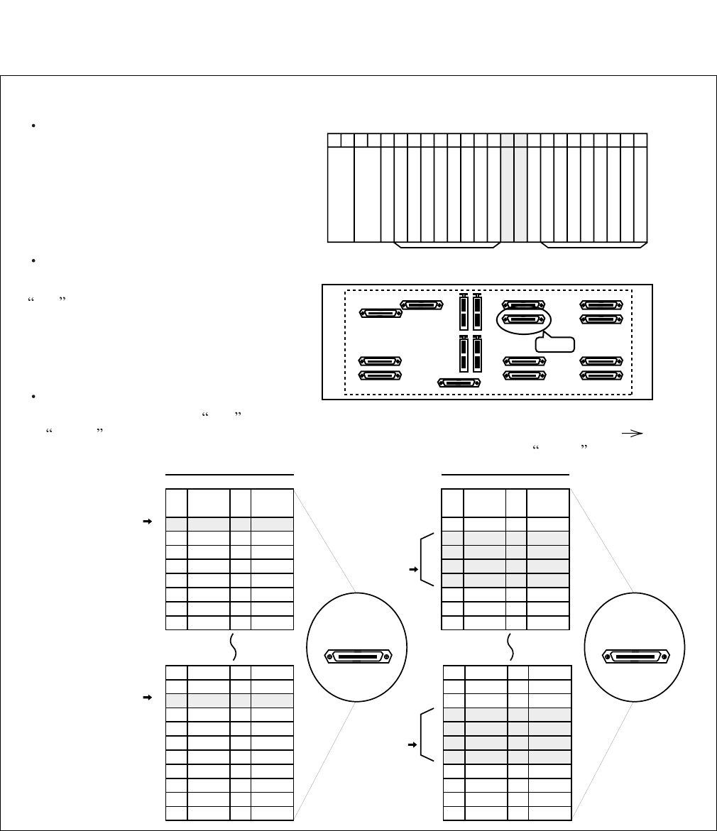
Figure 4-6 PLO Pin Assignments for Receiving Clock (1-IMG System)
00 01 02 03 04 05 06 07 08 09 10 11 12 13 14 15 16 17 18 19 20 21 22 23
Front View
PIM0
Universal Slots Universal Slots
PIN
No.
26
27
28
29
30
31
32
33
LEAD
NAME
DCSB0
DIU0B0
DIU1B0
DIU2B0
DIU3B0
SYN0B0
SYN1B0
LEAD
NAME
DCSA0
DIU0A0
DIU1A0
DIU2A0
DIU3A0
SYN0A0
SYN1A0
PIN
No.
1
2
3
4
5
6
7
8
PIN
No.
26
27
28
29
30
31
32
33
LEAD
NAME
DCSB0
DIU0B0
DIU1B0
DIU2B0
DIU3B0
SYN0B0
SYN1B0
LEAD
NAME
DCSA0
DIU0A0
DIU1A0
DIU2A0
DIU3A0
SYN0A0
SYN1A0
PIN
No.
1
2
3
4
5
6
7
8
40
41
42
43
44
45
46
47
48
49
50
15
16
17
18
19
20
21
22
23
24
25
DCSB1
DIU0B1
DIU1B1
DIU2B1
DIU3B1
SYN0B1
SYN1B1
DCSA1
DIU0A1
DIU1A1
DIU2A1
DIU3A1
SYN0A1
SYN1A1
40
41
42
43
44
45
46
47
48
49
50
15
16
17
18
19
20
21
22
23
24
25
DCSB1
DIU0B1
DIU1B1
DIU2B1
DIU3B1
SYN0B1
SYN1B1
DCSA1
DIU0A1
DIU1A1
DIU2A1
DIU3A1
SYN0A1
SYN1A1
PLO Connector PLO Connector
for PLO
equipped
with TSW #0
for PLO
equipped
with TSW #0
for PLO
equipped
with TSW #1
for PLO
equipped
with TSW #1
for receiveing clock from
a High-Stability Oscillator
for distributing clock from
a digital interface
Backplane
Since PLO circuit is equipped with TSW card, PLO input leads appear on the LT connector labeled PLO.
TSW mounting slots
TSW card is mounted in slots 13 and 14
of PIM0.
LT cable connector
Connect an LT cable to the connector labeled
PLO on PIM0 backplane.
PLO connector Pin Assignment
Pins are assigned as follows on PLO connector. When clock is distributed from a digital interface, use one pair
of DIUxxx leads among a maximum of 4 inputs. DIU leads have the following precedence: DIU0xx(High)
DIU3xx(Low). On the contrary, to receive clock from an external high-stability osillator, use DCSxx leads.
TSW
TSW
PIM0 PLO
CHAPTER 4 ND-71762 (E)
Page 38
Issue 2
INSTALLATION PROCEDURE
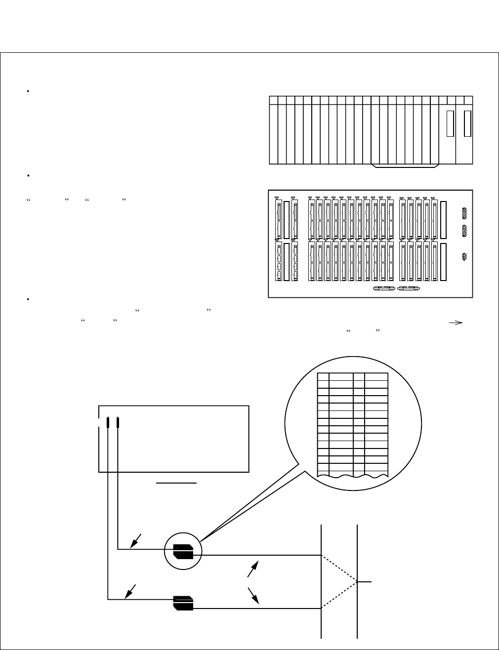
Figure 4-7 PLO Pin Assignment for Receiving Clock (4-IMG System)
00 01 02 03 04 05 06 07 08 09 10 11 12 13 14 15 16 17 18 19 20 21 22 23
Front View
TSWM
TSWM
TSW
Backplane
PLO input leads appear on the LT connectors labeled EXCLK0 and EXCLK1.
PLO mounting slots
PLO card is mounted in slots 21 and 23
of TSWM.
LT cable connectors
Connect LT cables to the connectors labeled
EXCLK0 and EXCLK1 on the TSWM backplane.
EXCLK0/EXCLK1 connector Pin Assignment
Pins are assigned as follows on EXCLK0/EXCLK1 connector. When clock is distributed from a digital interface,
use one pair of DIUxxx leads among a maximum of 4 inputs. DIU leads have the following precedence: DIU0xx(High)
DIU3xx(Low). On the contrary, to receive clock from an external high-stability osillator, use DCSxx leads.
PLOEXCLK1
EXCLK0 PLO
EXCLK0
EXCLK1
34PH EXCLK CA-A
34PH EXCLK CA-A
REAR VIEW
EXCLK0
EXCLK1
TSWM
MDF
Installation Cable To Digital Interface and/or DCS
34PH EXCLK CA-A Cable Lead Accommodation
26
27
28
29
30
31
32
33
34
35
36
37
38
1
2
3
4
5
6
7
8
9
10
11
12
13
FM1
FM0
SYN1B
SYN0B
DIU3B
DIU2B
DIU1B
DIU0B
DCSB
E
E
SYN1A
SYN0A
DIU3A
DIU2A
DIU1A
DIU0A
DCSA
ND-71762 (E) CHAPTER 4
Page 39
Issue 2
INSTALLATION PROCEDURE
Figure 4-8 Cable Connection Diagram for Accepting Synchronization Clocks from an External High-
Stability Oscillator (TSW)
MDF
PBX
Cable Connection Diagram
Provide the following wirings at the MDF. The following connection diagram shows an example where the
system has the TSW cards in a dual configuration.
(External
Oscillator)
CLK
(External
Oscillator)
CLK
PCM Cable(IP)
PCM Cable(IP)
DCSA0
DCSB0
DCSB1
DCSA1
LT Connector Cable
PLO
PLO
TSW
BASEU
maximum 400 meters (1320feet) (24AWG)
M-OSC #0
(Master Oscillator)
/EXT. OSC #0
M-OSC #1
(Master Oscillator)
/EXT. OSC #1

CHAPTER 4 ND-71762 (E)
Page 40
Issue 2
INSTALLATION PROCEDURE
Figure 4-9 Cable Connection Diagram for Accepting Synchronization Clocks from an External High-
Stability Oscillator (PLO)
MDF
ISW
Cable Connection Diagram
Provide the following wirings at the MDF. The following connection diagram shows an example where the
system has the PLO cards in a dual configuration.
(External
Oscillator)
CLK
(External
Oscillator)
CLK
PCM Cable(IP)
PCM Cable(IP)
DCSA
DCSB
LT Connector Cable
EXCLK1
DCSB
DCSA
LT Connector Cable
EXCLK0
EXCLK1
PLO#1
EXCLK0
PLO#0
BASEU
maximum 400 meters (1320feet) (24AWG)
Note: This diagram shows connections for a system having dual PLOs.
M-OSC #1
(Master Oscillator)
/EXT. OSC #1
M-OSC #0
(Master Oscillator)
/EXT. OSC #0
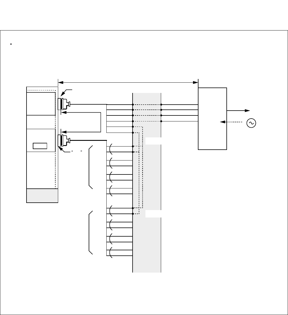
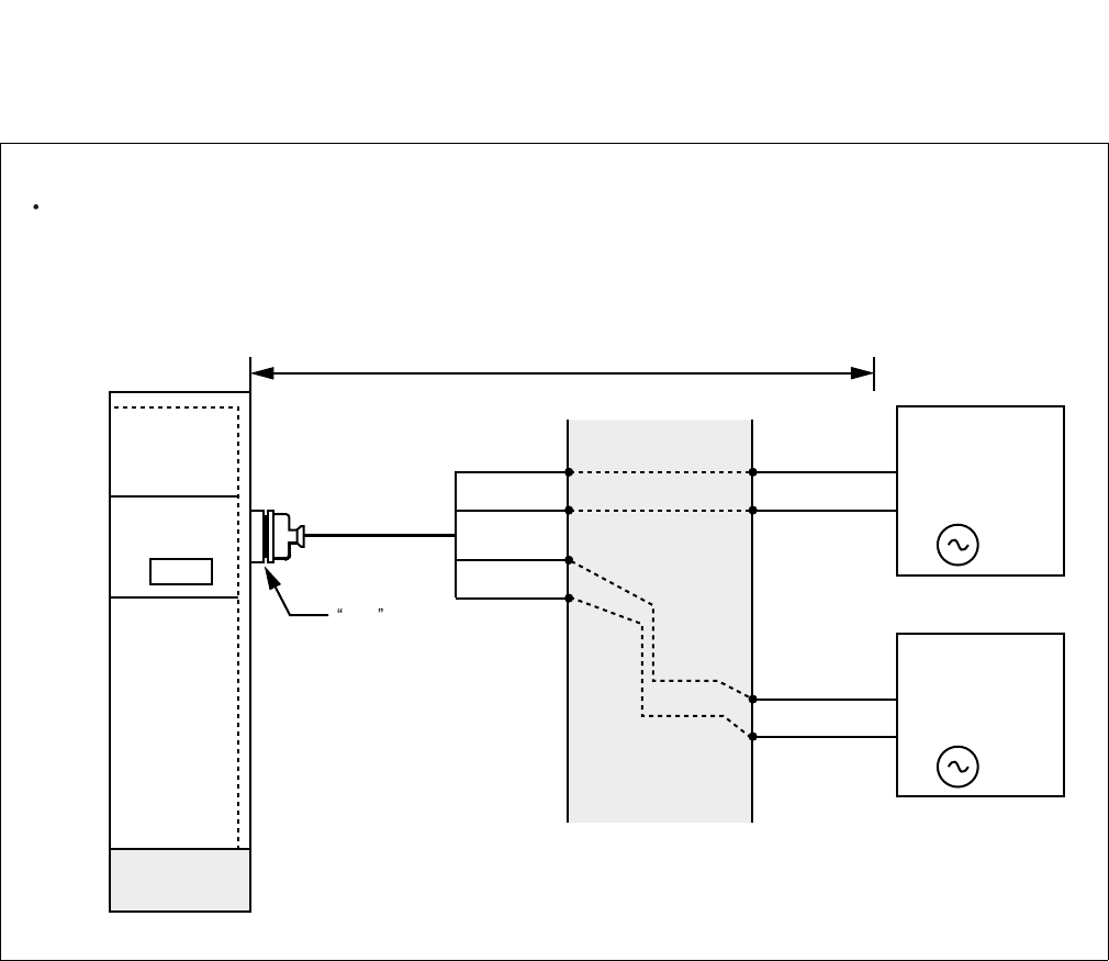
ND-71762 (E) CHAPTER 4
Page 41
Issue 2
INSTALLATION PROCEDURE
Figure 4-10 Cable Connection Diagram for Receiving Clock from a Digital Interface (TSW)
MDF
PBX
Cable Connection Diagram
Perform the following wirings at the MDF. The following connection diagram shows an example where the
Digital Trunk POUT leads are used as the 1st clock distribution route.
PCM
Carrier
Equipment/
DSU
CLK
PCM Cable(2P)
LT Connector
PLO
PLO
TSW
BASEU
maximum 200 meters (660feet) (24AWG)
to other node
RA
RB
TA
TB
POUTA
POUTB
DIU0A0
DIU0B0
DIU1A0
DIU1B0
DIU2A0
DIU2B0
DIU3A0
DIU3B0
DIU0A1
DIU0B1
DIU1A1
DIU1B1
DIU2A1
DIU2B1
DIU3A1
DIU3B1
#1
#2
#3
#4
#1
#2
#3
#4
for PLO #0
for PLO #1
Installation Cable
Installation Cable
maximum100
meters(330 feet)
Digital
Interface
Note 1
Note 1:
Note 2:
Note 2
PLO has a maximum of 4 inputs. DIU0xx leads are used for the 1st clock distribution routs. Thus,
DIU3xx leads are used for the 4th. The first input has the highest priority.
This connection is required for a dual-TSW system.
(24AWG)
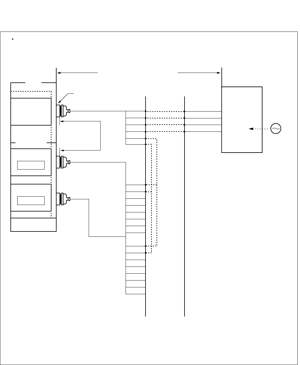
CHAPTER 4 ND-71762 (E)
Page 42
Issue 2
INSTALLATION PROCEDURE
Figure 4-11 Cable Connection Diagram for Receiving Clock from a Digital Interface (PLO)
DIU0A1
DIU0B1
DIU1A1
DIU1B1
DIU2A1
DIU2B1
DIU3A1
DIU3B1
DIU0A0
DIU0B0
DIU1A0
DIU1B0
DIU2A0
DIU2B0
DIU3A0
DIU3B0
RA
RB
TA
TB
POUT A
POUT B
PCM Cable (2P) to other node
PCM
Carrier
Equipment
DSU
CLK
Note 1:
Note 2
Note 1
PLO has a maximum of 4 inputs. DIU0xx leads are used for the 1st clock distribution routes.
Thus, DIU3xx leads are used for the 4th. The first input has the highest priority.
Note 2: The connection is required for a dual PLO system.
MDF
maximum 100
meters (330 feet)
(24AWG)
Installation Cable
LT Connector
Installation Cable
Installation Cable
EXCLK1
PLO#1
EXCLK0
PLO#0
Digital
Interface
IMG
IMG/ISWM
maximum 200 meters (660feet) (24AWG)
This figure shows an example of distributing clock from a digital interface. This example also assumes that the Digital
Trunk POUT leads are used as the 1st clock distribution route.
Cable Connection Diagram
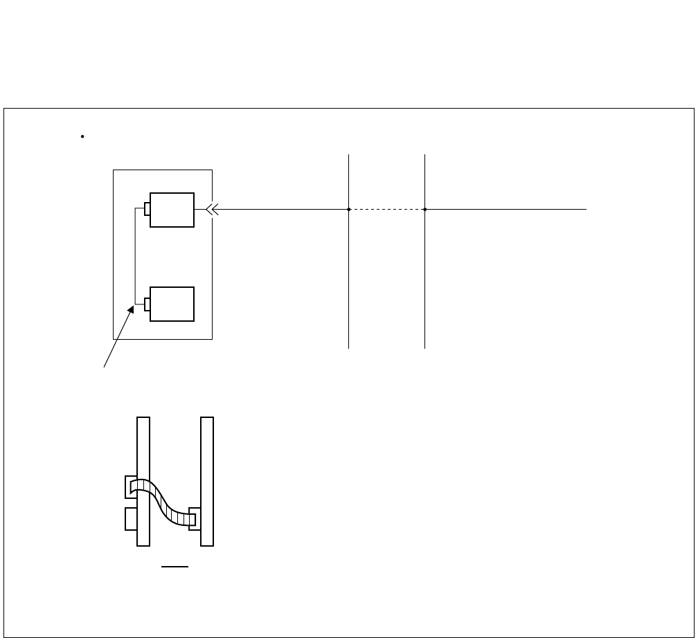
ND-71762 (E) CHAPTER 4
Page 43
Issue 2
INSTALLATION PROCEDURE
3.4 Front Cable Connection between DTI and CCH
Figure 4-12 Front Cable Connections between DTI/CCT and CCH
PBX
DTI/CCT
CCH
Note 1
Note 2
MDF
CCIS Line
When MODEM is not used
Front Cable connection
CCH DTI/CCT
CNx
TRK
Front
Note 1: For cross connections between DTI and CCIS Line, refer to Figure 4-10 and 4-11.
Note 2: The connector name varies depending on the card.
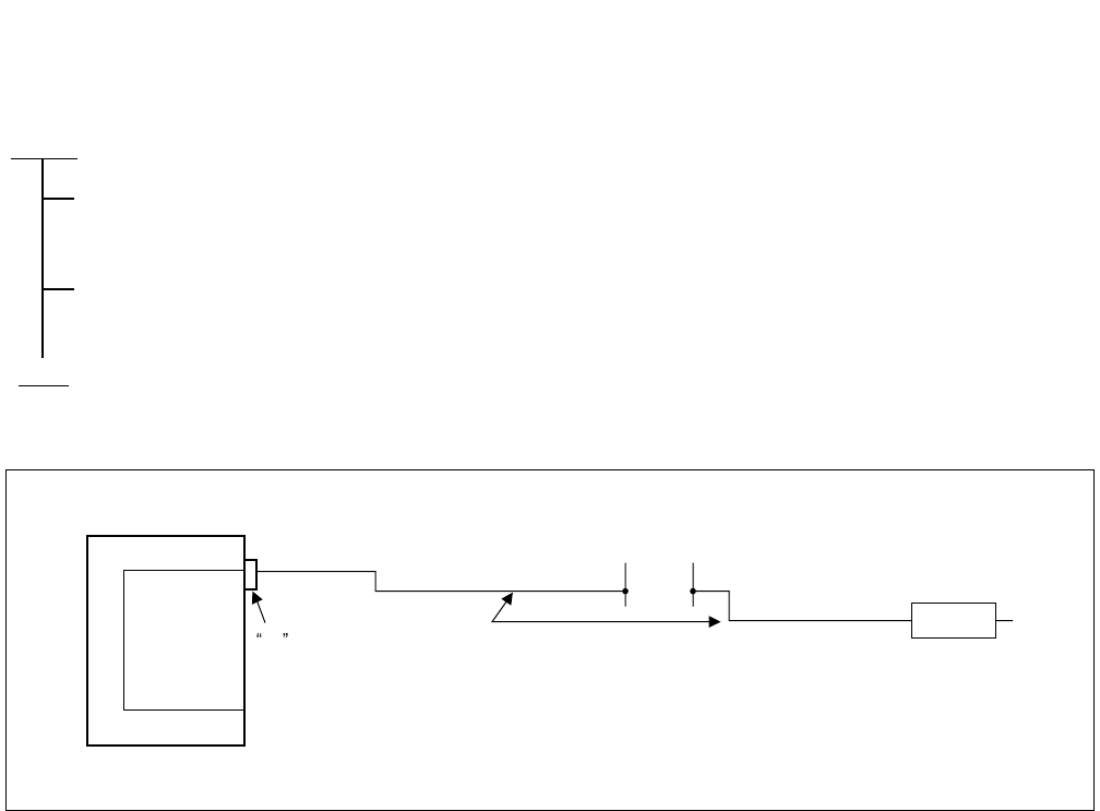
CHAPTER 4 ND-71762 (E)
Page 44
Issue 2
INSTALLATION PROCEDURE
3.5 Cable Running from PBX to the MODEM for Analog CCIS Line
Figure 4-13 Connection of MODEM Cables for Analog CCIS Line
START
By referring to Figure 4-15 through 4-16, confirm the connector name on the PIM backplane, then
connect the installation cable (25P) to the LT connector.
Connect the MODEM which is connected to analog CCIS line to the installation cable.
END
PBX
PA-2CCHA
LT CONNECTOR INSTALLATION CABLE
MDF
MODEM
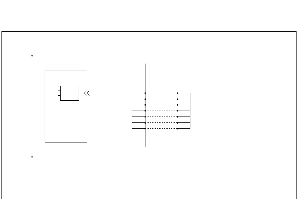
ND-71762 (E) CHAPTER 4
Page 45
Issue 2
INSTALLATION PROCEDURE
Figure 4-14 Connecting Route Diagram for CCH
PBX
CCH RD
MDF
MODEM
When MODEM is used
RD
SG SG
ER ER
RT RT
ST2 ST2
RS RS
SD SD
Cable length is maximum 15 meters (50 feet).
The MODEM to be used is a synchronous MODEM of 2400, 4800,
or 9600 bps, and the communication method is limited to 4-wire full
duplex communications.
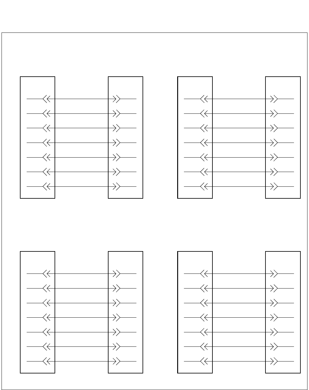
CHAPTER 4 ND-71762 (E)
Page 46
Issue 2
INSTALLATION PROCEDURE
Figure 4-15 Connection between PBX and MODEM
(a) Cable Connection when Accommodated in *1 (Refer to Figure 4-16)
4-SD0 2-SD
LT
Connector
1-RD0 3-RD
29-RS0 4-RS
27-SG0 7-SG
3-ST20 15-ST2
28-RT0 17-RT
2-ER0 20-ER
PBX MODEM
8-SD1 2-SD
LT
Connector
5-RD1 3-RD
33-RS1 4-RS
31-SG1 7-SG
7-ST21 15-ST2
32-RT1 17-RT
6-ER1 20-ER
PBX MODEM
(Circuit No. 0) (Circuit No. 1)
(b) Cable Connection when Accommodated in *2 (Refer to Figure 4-16)
20-SD0 2-SD
LT
Connector
17-RD0 3-RD
45-RS0 4-RS
43-SG0 7-SG
19-ST20 15-ST2
44-RT0 17-RT
18-ER0 20-ER
PBX MODEM
24-SD1 2-SD
LT
Connector
21-RD1 3-RD
49-RS1 4-RS
47-SG1 7-SG
23-ST21 15-ST2
48-RT1 17-RT
22-ER1 20-ER
PBX MODEM
(Circuit No. 0) (Circuit No. 1)
LT
Connector
LT
Connector
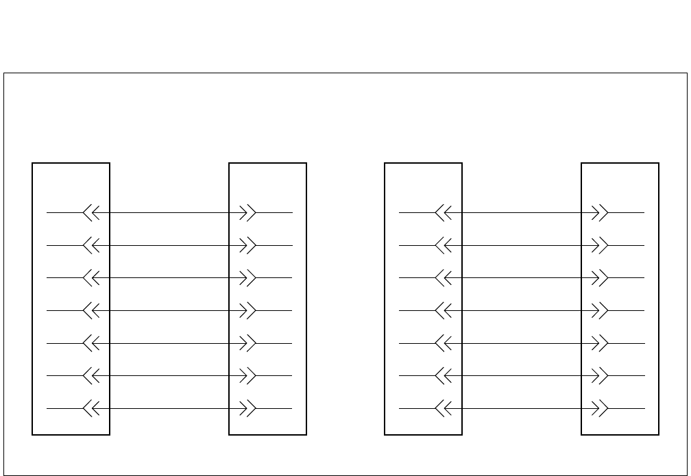
ND-71762 (E) CHAPTER 4
Page 47
Issue 2
INSTALLATION PROCEDURE
Figure 4-15 Connection between PBX and MODEM (Continued)
(c) Cable Connection when Accommodated in *3. (Refer to Figure 4-16)
12-SD0 2-SD
LT
Connector
9-RD0 3-RD
37-RS0 4-RS
35-SG0 7-SG
11-ST20 15-ST2
36-RT0 17-RT
10-ER0 20-ER
PBX MODEM
16-SD1 2-SD
LT
Connector
13-RD1 3-RD
41-RS1 4-RS
39-SG1 7-SG
15-ST21 15-ST2
41-RT1 17-RT
14-ER1 20-ER
PBX MODEM
(Circuit No. 0) (Circuit No. 1)
LT
Connector
LT
Connector
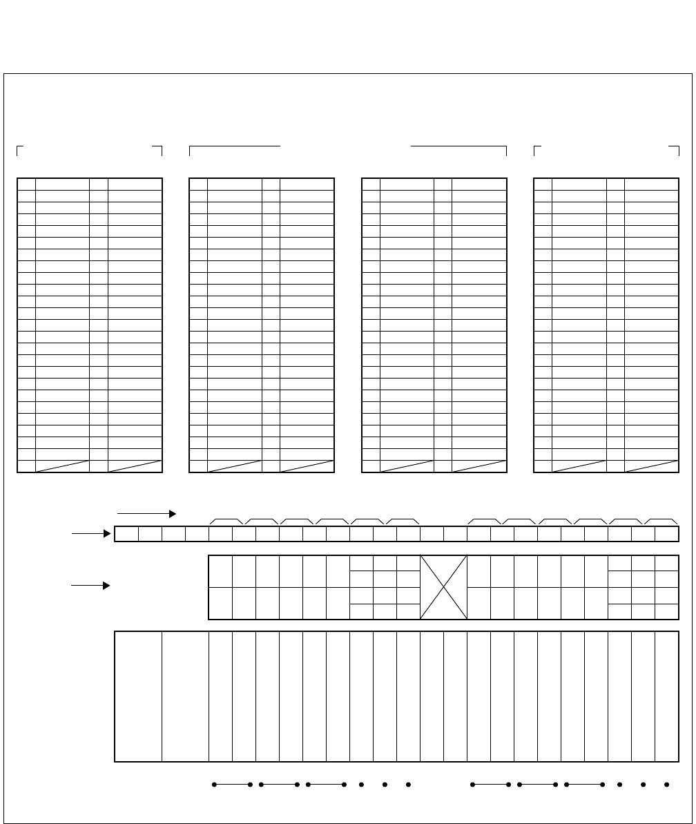
CHAPTER 4 ND-71762 (E)
Page 48
Issue 2
INSTALLATION PROCEDURE
Figure 4-16 LT Connector Leads Accommodation for 2CCH
1
Highway Block
26 1 RD0
27 SG0 2 ER0
28 RT0 3 ST2 0
29 RS0 4 SD0
41 16
40 RDB1 15 RDA1
39 TDB1 14 TDA1
38 SCKB1 13 SCKA1
37 12
36 RDB0 11 RDA1
33 RS1 8 SD1
32 RT1 7 ST2 1
31 SG1 6 ER1
30 5 RD1
35 TDB0 10 TDA0
34 SCKB0 9 SCKA0
48 23
47 22
46 21
44 19
45 20
43 18
42 17
49 24
50 25
LT0, 2, 4, 6, 8, 10 Connector
Accommodated in *1
26 1
27 2
28 3
29 4
41 16
40 15
39 14
38 13
37 12
36 11
33 8
32 7
31 6
30 5
35 10
34 9
48 RT1 23 ST2 1
47 SG1 22 ER1
46 21 RD1
44 RT0 19 ST2 0
45 RS0 20 SD0
43 SG0 18 ER0
42 17 RD0
49 RS1 24 SD1
50 25
LT0, 2, 4, 6, 8, 10 Connector
Accommodated in *2
26 SCKB0 1 SCKA0
27 TDB0 2 TDA0
28 RDB0 3 RDA0
29 4
41 16
40 15
39 14
38 13
37 12
36 11
33 8
32 RDB1 7 RDA1
31 TDB1 6 TDA1
30 SCKB1 5 SCKA1
35 10
34 9
48 23
47 22
46 21
44 19
45 20
43 18
42 17
49 24
50 25
LT1, 3, 5, 7, 9, 11 Connector
02 03 04 05 06 07 08 09 10 11 12 13 14 15 16 17 18 19 2000 01 21 22 23
01 03 05 07 09 11 14 18
23 07 15 19 23
22
06
14 18 22
00 02 04 06 08 10 12 16
21
09 11
13 17 21
20 08 10 12 16 20
*3
*2
*3
*1
*1
*2
*3
*1
*2
*3
0 2345 67891011
LT0 LT1 LT2 LT3 LT4 LT5 LT8 LT9 LT10 LT11
LT Connector Name
Slot No.
Group No.
PIM
13 17
15 19 01
00
03
02
05
04
LT6 LT7
*2
*1
26 1
27 2
28 3
29 4
41 RS1 16 SD1
40 RT1 15 ST2 1
39 SG1 14 ER1
38 13 RD1
37 RS0 12 SD0
36 RT0 11 ST2 0
33 8
32 7
31 6
30 5
35 SG0 10 ER0
34 9 RD0
48 RDB1 23 RDA1
47 TDB1 22 TDA1
46 SCKB1 21 SCKA1
44 RDB0 19 RDA0
45 20
43 TDB0 18 TDA0
42 SCKB0 17 SCKA0
49 24
50 25
LT1, 3, 5, 7, 9, 11 Connector
Accommodated in *3
LT Connector Accommodation
PWR
PWR
*3
*2
*1
*3
*2
*1

ND-71762 (E) CHAPTER 5
Page 49
Issue 2
INSTALLATION TEST PROCEDURE
CHAPTER 5 INSTALLATION TEST PROCEDURE
1. GENERAL
This chapter describes the installation tests that are performed after system start up and after the office data has been
assigned. The following test procedure are covered.
• Overall Test for CCIS Line
• CCIS Service Feature Functional Test
2. INSTALLATION TEST PROCEDURE
2.1 Overall Test for CCIS Line
Tests are to be performed to check CCIS Lines by connecting them to a trunk on an individual basis.
The speech path conditions (speech level, presence of noise, one-way speech, no speech, etc.) over the connection
to the distant office will be checked. Release of the trunk used will also be checked.
• Overall Test Procedure
START
Overall Test of CCIS Tie Line Outgoing Call: Paragraph 2.1.1
Overall Test of CCIS Tie Line Incoming Call: Paragraph 2.1.2
Test of Connection and Alternate Routing to All Tie Lines: Paragraph 2.1.3
Test of Tandem Connection to Tie Line: Paragraph 2.1.4
PAD Setting: Paragraph 2.1.5
END
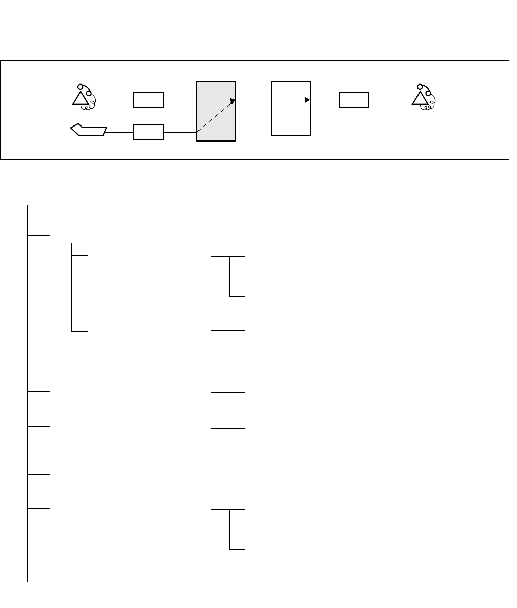
CHAPTER 5 ND-71762 (E)
Page 50
Issue 2
INSTALLATION TEST PROCEDURE
2.1.1 Overall Test of CCIS Tie Line Outgoing Call
LC LC
(PBX to be tested)
ATTCON
Station A’
ATI
PBX
Station B’
OFFICE A OFFICE B
PBX
START
Seizure of trunk to be tested
When seizing from a
station
Place the trunk to be tested into idle state, and make
busy all other trunks.
Station A’ dials the number for station B’ in the B
Office.
When seizing from an
ATTCON
An ATTCON sets up the connection with a specific
trunk designated by Individual Trunk Access for CCIS
TRK service and dials the number for Station B’ in the
B Office.
Call termination to Station B’ in
the B Office
The call terminates to Station B’ via a CCIS Tie Line.
Check of speech conditions After the call has been answered at the ATTCON,
check the speech conditions including speech level,
presence of noise and one-way speech state.
Release
When all CCIS Tie Line Trunks
have been checked and a fault
has been detected
Perform fault localization procedure when a fault has
occurred to CCIS Tie Line (See Procedure A)
If the distant office is faulty, make a request to the
distant office for repair.
END
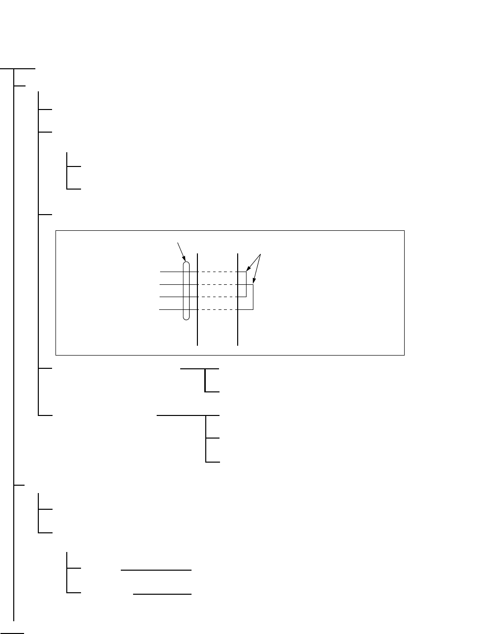
ND-71762 (E) CHAPTER 5
Page 51
Issue 2
INSTALLATION TEST PROCEDURE
(Procedure A)
START
A DTI/CCT is in use as the speech lines of No. 7 CCIS.
On the DTI/CCT card, set its MB switch UP.
In any office other than the Clock Master Office, disconnect the DTI cable connector at the DTI side
(Back place of the PIM)
PLO alarm is generated, but ignore it.
The PLO starts running by itself.
Make the following connection at the MDF using a paired wire.
The DTI does not recover. System message “3-J” is not displayed.
(CCH/CCT Link Failure may
occur, but ignore it.) The DTI/CCT is faulty.
The DTI recovered. System message “3-J” is not displayed.
(CCH/CCT Link Failure may
occur, but ignore it.) The DTI/CCT is normal.
Call the distant office and ask for repair.
An analog trunk is in use as the speech lines of No. 7 CCIS.
Remove the cross connection wires and disconnect them from the external line side.
Connect a telephone set to the trunk accommodating terminals concerned on the MDF, and talk with
the caller.
Normal Call the Distant Office and ask for repair.
Abnormal Replace the trunk card with a spare card.
END
TA
TB
RA
RB
DTI/CCT
LEADS MDF CROSS
CONNECTION
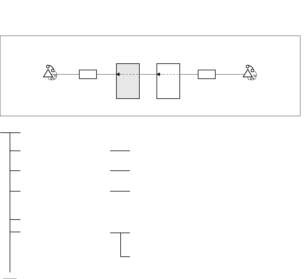
CHAPTER 5 ND-71762 (E)
Page 52
Issue 2
INSTALLATION TEST PROCEDURE
2.1.2 Overall Test of CCIS Tie Line Incoming Call
START
Seizure of trunk to be tested Place the trunk to be tested into idle state, and make busy all
other trunks.
Termination of incoming call
to station A’ in the self office
An incoming call from the distant office terminates to Station
A’.
Check of speech After the call has been answered at Station A’, check the
speech conditions including speech level, presence of noise
and one-way speech state.
Release
When all CCIS Tie Line
Trunks have been checked and
a fault has been detected
Perform fault localization procedure when a fault has occurred
to CCIS Tie Line. (See Procedure A of Paragraph 2.1.1)
If the distant office is faulty, make a request to the distant
office for repair.
LC LC
(PBX to be tested)
OFFICE A
STATION A’ OFFICE B STATION B’
PBX
PBX
END

ND-71762 (E) CHAPTER 5
Page 53
Issue 2
INSTALLATION TEST PROCEDURE
2.1.3 Test of Connection and Alternate Routing to All Tie Lines
START
Test the trunks in the primary
route one at a time
Make busy all trunks in the primary route except the trunk to
be tested.
Station “A” calls Station “B” via the primary route.
After Station “B” answers, check the normality of the speech
condition including the speech level, presence of noise, and
one-way speech.
Release.
Make all the trunks in the
primary route busy.
Test the trunks in the alternate
route one at a time.
Make busy all trunks in the alternate route except the trunk to
be tested.
Station “A” calls Station “B” via the alternate route.
After Station “B” answers, check the normality of the speech
condition including the speech level, presence of noise, and
one-way speech.
Release.
Cancel the Make Busy
condition of the trunks.
END
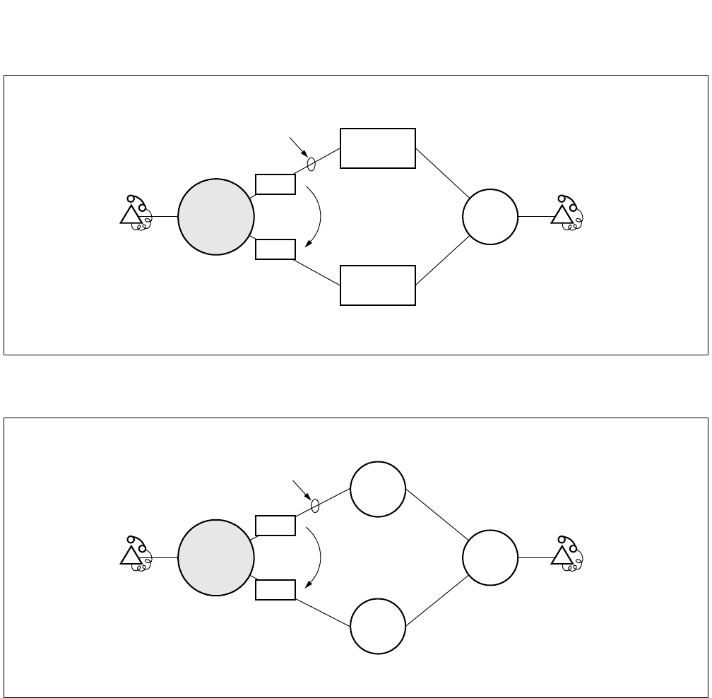
CHAPTER 5 ND-71762 (E)
Page 54
Issue 2
INSTALLATION TEST PROCEDURE
Figure 5-1 Combination of Tie Line Network and Public Network
Figure 5-2 Tie Line Network
Station A Station B
Alternate
Route
Basic/Primary Route
PBX
Tie Line
Network
Public
Network
TRKs
TRKs
PBX to be
tested
Station A Station B
Alternate
Route
Basic/Primary Route
PBX
TRKs
TRKs
PBX
PBX
PBX to be
tested
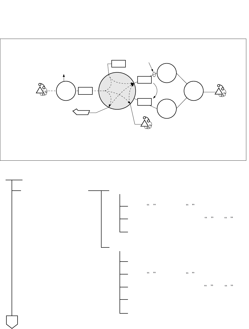
ND-71762 (E) CHAPTER 5
Page 55
Issue 2
INSTALLATION TEST PROCEDURE
2.1.4 Test of Tandem Connection to Tie Line
Figure 5-3 Test of Tandem Connection to Tie Line
PBX
PBX
PBX
STATION A ALTERNATE
ROUTE
TRKs
TRKs
PBX
ATTCON
IRT BASIC/PRIMARY ROUTE
STATION C
STATION B
PBX
(1)
(2)
(3)
(1): Direct tandem connection by dial-in
(2): Tandem connection via ATTCON
(3): Tandem connection via Station
TRKs
Station A calls Station B .
Release.
Test of Alternate Route.
Make busy all the trunks in the primary route.
START
Station A calls Station B .
Test of direct dial-in tandem
connection
Test of Basic/Primary Route
Confirm speech between Stations A and B .
Confirm speech between Stations A and B .
Release.
Make idle all the trunks.
A
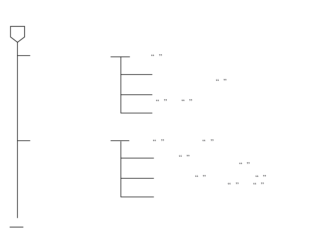
CHAPTER 5 ND-71762 (E)
Page 56
Issue 2
INSTALLATION TEST PROCEDURE
Release.
END
Test of tandem connection
via ATTCON
Test of tandem connection
via station
Staton A dials the access code for the ATTCON.
Station A calls Station C .
A
The ATTCON answers and sets up a tandem
connection to Station B .
The ATTCON releases, and speech between Station
A and B is confirmed.
Release.
Station C , after answering, makes a Switch Hook
Flash (SHF) and calls Station B .
After Station B answers, Station C releases.
Speech between Stations A and B is confirmed.
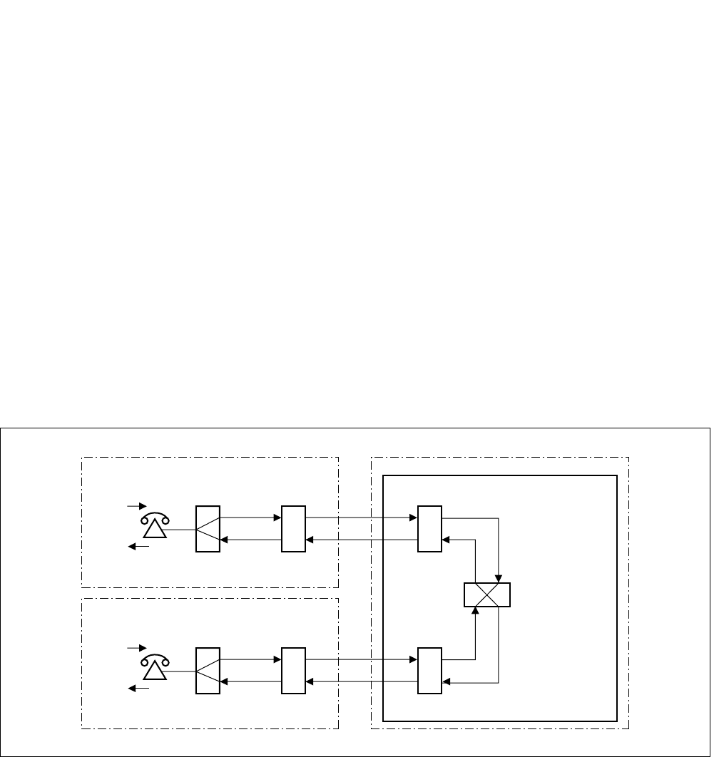
ND-71762 (E) CHAPTER 5
Page 57
Issue 2
INSTALLATION TEST PROCEDURE
2.1.5 PAD Setting
When setting up a No.7 CCIS Network, PAD setting differs from that in the case of analog network.
(a) For an outgoing call to/incoming call from a Tie Line:
• Via “ARTD” command (CDN=30) or by switch setting on the circuit card (DTI/CCT).
(b) For a tandem Tie Line connection:
• Via “APAD” command or switch setting on the circuit card
<EXAMPLE>
At both the originating and terminating offices, 0 dB is set to the outgoing side and 8 dB is set to the terminating of
the DTI/CCT route via “ARTD” command or switch settings.
At the tandem office, 0 dB is set for both the terminating and originating sides of each DTI/CCT route via “APAD”
command.
This arrangement is shown in Figure 5-4.
Figure 5-4 Example of PAD Setting for CCIS
ORIGINATING OFFICE
TERMINATING OFFICE
0dB
-8dB
-8dB
0dB
DTI/CCT
DTI/CCT
-8dB
-8dB
0dB
0dB
DTI/CCT
0dB
0dB
0dB
0dB
TANDEM OFFICE

CHAPTER 5 ND-71762 (E)
Page 58
Issue 2
INSTALLATION TEST PROCEDURE
2.2 CCIS Service Feature Functional Test
The purpose of this test is to verify that CCIS service features are programmed and operate as per the Job Specifi-
cation.
For the operating procedure pertaining to each service feature, refer to CHAPTER 7: “List of Service Features for
CCIS (1/2)”.
• CCIS Service Feature Functional Test Procedure
START
Test of Interoffice Station to Station Connection: Paragraph 2.2.1
Test of Outgoing Call Connection to Tie Line Trunk: Paragraph 2.2.2
Test of Transfer Services: Paragraph 2.2.3
Test of Services from ATTCON: Paragraph 2.2.4
Test of other Services: Paragraph 2.2.5
END
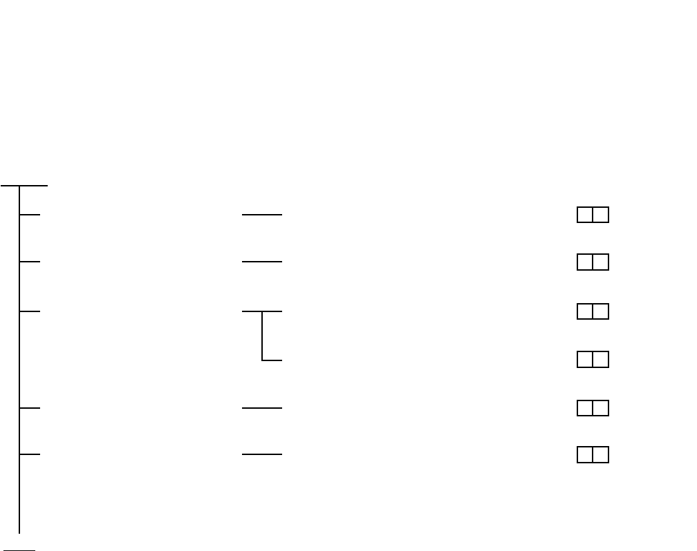
ND-71762 (E) CHAPTER 5
Page 59
Issue 2
INSTALLATION TEST PROCEDURE
2.2.1 Test of Interoffice Station to Station Connection
Test Outline:
Tests are to be performed on interoffice station to station connection and on normal operations of various system
services.
START
END
Trunk Line Check No. 7 CCIS Line
Busy Line Service Check Step Call-CCIS (S-59)
Bridge-In Service Check Call Back-CCIS (C-44)
Executive Right-of-Way-CCIS (E-8)
Ring Back Tone Check Voice Call-CCIS (V-7)
Ringing Check Distinctive Ringing-CCIS (D-75)

CHAPTER 5 ND-71762 (E)
Page 60
Issue 2
INSTALLATION TEST PROCEDURE
2.2.2 Test of Outgoing Call Connection to Tie Line Trunk
Test Outline:
Tests are to be performed to determine whether outgoing trunk connections to each route, restriction of connections
services when all trunks are busy, etc. operate as specified.
START
END
All Trunk Busy Service Check Outgoing Trunk Queuing-CCIS (O-12)
SMDS Service Check Centralized Billing-CCIS (C-55)
Centralized Management
Service Check
Centralized System Management Report-CCIS (C-57)
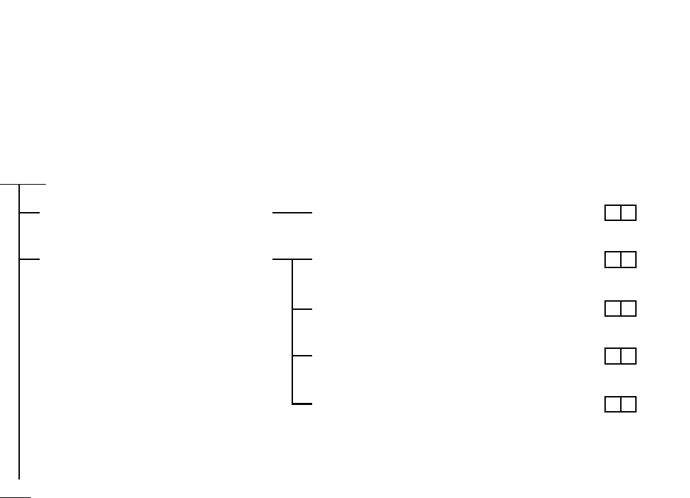
ND-71762 (E) CHAPTER 5
Page 61
Issue 2
INSTALLATION TEST PROCEDURE
2.2.3 Test of Transfer Services
Test Outline:
Tests are to be performed on interoffice transfer services when the call has encountered line busy or when the call
has not been answered.
START
END
Transfer Service Check Call Transfer-All Calls-CCIS (C-50)
Call Forwarding Service Check Call Forwarding-All Calls-CCIS (C-45)
Call Forwarding-Busy Line-CCIS (C-46)
Call Forwarding-Don’t Answer-CCIS (C-47)
Call Forwarding Assignment-Attendant-
CCIS (C-94)
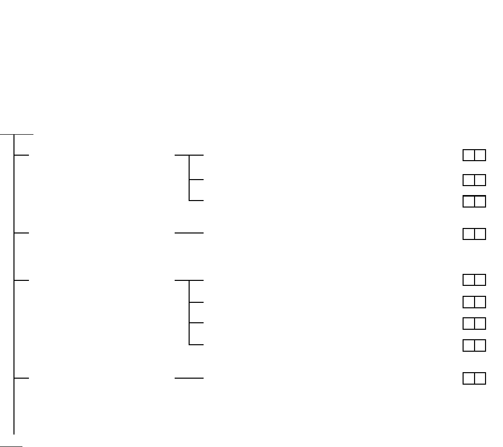
CHAPTER 5 ND-71762 (E)
Page 62
Issue 2
INSTALLATION TEST PROCEDURE
2.2.4 Test of Services from ATTCON
Test Outline:
Tests are to be performed on the functions of the Attendant Console (ATTCON) and various interoffice services to
be provided via the ATTCON.
START
END
Call Termination to
ATTCON Check
Attendant Camp-on with Tone Indication-CCIS (A-45)
Serial Call-CCIS (S-52)
Busy Verification-CCIS (B-9)
Information Display on
ATTCON Check
Calling Number Display-CCIS (C-52)
Night Service Check Direct-In-Termination-CCIS (D-74)
Night Connection-Fixed-CCIS (N-15)
Centralized Day/Night Mode Change-CCIS (C-56)
LDN Night Connection-CCIS (L-29)
Other Service Check Individual TRK Access-CCIS (I-19)

ND-71762 (E) CHAPTER 5
Page 63
Issue 2
INSTALLATION TEST PROCEDURE
2.2.5 Test of other Services
Test Outline:
Tests are to be performed on various kinds of interoffice services when Dterm, etc. are used.
START
END
Message Reminder-CCIS (M-34)
Message Waiting Lamp Setting-Attendant-CCIS (M-35)
Message Waiting Lamp Setting-Station-CCIS (M-36)
Data Line Service Data Communication-CCIS (D-41)

CHAPTER 5 ND-71762 (E)
Page 64
Issue 2
INSTALLATION TEST PROCEDURE
3. TEST RESULT REPORT
3.1 CCIS Service Feature Functional Test
3.1.1 Test of Interoffice Station to Station Connection
3.1.2 Test of Outgoing Call Connection to Tie Line Trunk
3.1.3 Test of Transfer Services
SERVICE FEATURE
SPECIAL
ACCESS
CODE
PROVIDED CHECK REMARKS
Line Check No.7 CCIS Line
Busy Line
Service Check
Step Call-CCIS (S-59)
Bridge-In
Service Check
Call Back-CCIS (C-44)
Executive Right of Way-CCIS (E-8)
Ring Back
Tone Check
Voice Call-CCIS (V-7)
Ringing Check Distinctive Ringing-CCIS (D-75)
SERVICE FEATURE
SPECIAL
ACCESS
CODE
PROVIDED CHECK REMARKS
All Trunk
Busy Service
Check
Outgoing Trunk Queuing-CCIS
(O-12)
SMDS
Service Check
Centralized Billing-CCIS (C-55)
Centralized
Management
Service Check
Centralized System Management
Report-CCIS (C-57)
SERVICE FEATURE
SPECIAL
ACCESS
CODE
PROVIDED CHECK REMARKS
Transfer
Service
Check
Call Transfer-All Calls-CCIS (C-50)
Call Forwarding-All Calls-CCIS
(C-45)

ND-71762 (E) CHAPTER 5
Page 65
Issue 2
INSTALLATION TEST PROCEDURE
3.1.4 Test of Services from ATTCON
3.1.5 Test of Other Services
SERVICE FEATURE
SPECIAL
ACCESS
CODE
PROVIDED CHECK REMARKS
Call
Forwarding
Service Check
Call Forwarding-Busy Line-CCIS
(C-46)
Call Forwarding-Don’t Answer-CCIS
(C-47)
Call Forwarding Assignment-
Attendant-CCIS (C-94)
SERVICE FEATURE
SPECIAL
ACCESS
CODE
PROVIDED CHECK REMARKS
ATTCON
Call
Termination
Check
Attendant Camp-on with Tone
Indications-CCIS (A-45)
Serial Call-CCIS (S-52)
Busy Verification-CCIS (B-9)
ATTCON
Display
Function
Check
Calling Number Display-CCIS
(C-52)
Night Service
Check
Direct-In Termination-CCIS (D-74)
Night-Connection-Fixed-CCIS
(N-15)
Centralized Day/Night Mode Change
CCIS (C-56)
LDN Night Connection-CCIS (L-29)
Other Service
Check
Individual Trunk Access-CCIS (I-19)
SERVICE FEATURE
SPECIAL
ACCESS
CODE
PROVIDED CHECK REMARKS
Message Reminder-CCIS (M-34)
Message Waiting Lamp
Setting-Attendant-CCIS (M-35)
Message Waiting Lamp
Setting-Station-CCIS (M-36)
Data Line
Service
Data Communication-CCIS (D-41)

CHAPTER 6 ND-71762 (E)
Page 66
Issue 2
BASIC DATA ASSIGNMENT
CHAPTER 6 BASIC DATA ASSIGNMENT
1. GENERAL
This chapter explains how to program office data which are necessary for establishing a CCIS Tie Line Connection.
For easy understanding, office data programming is explained using an example of a CCIS network in this chapter.
Accordingly, when programming data at your site, some minor data modifications may be unavoidable. For other
features associated with CCIS, see CHAPTER 7 “List of Service Features for CCIS (1/2)”.
24CCT/30CCT
This circuit card provides an interface between 24/30 trunks and the PBX at 1.544/2.048 Mbit/s. Being equipped
with a Common Channel Handler (CCH), this circuit card can be used as an interface for a Common Channel Inter-
office Signaling (CCIS) network.
2CCH
This circuit card provides two Common Channel Handlers (CCH). By using together with 24DTI/30DTI to establish
the digital CCIS line or used as an interface for the analog CCIS.
24DTI/30DTI
This circuit card provides an interface for a digital CCIS line, using together with the 2CCH card.
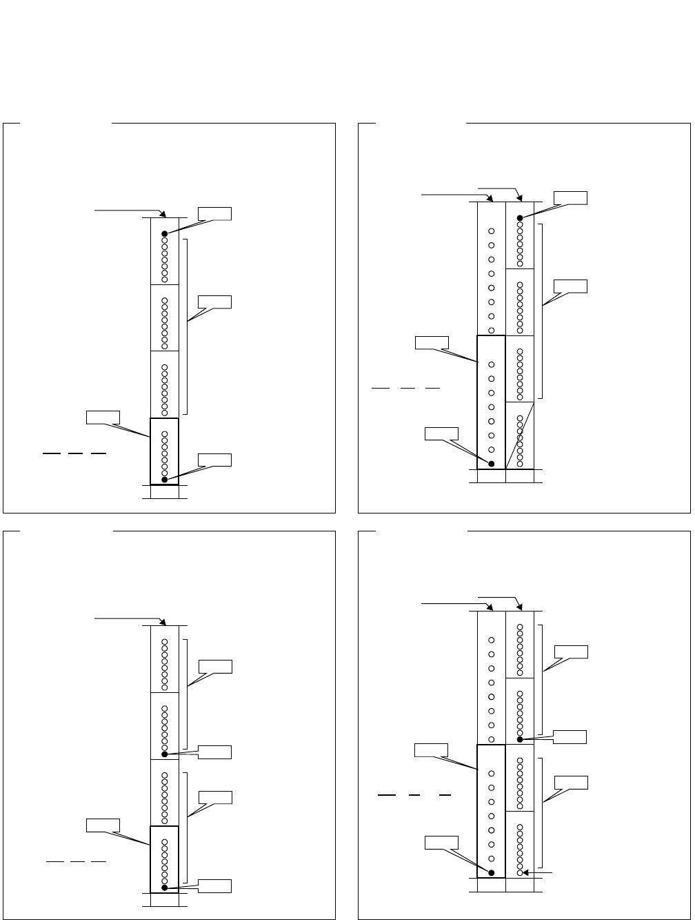
ND-71762 (E) CHAPTER 6
Page 67
Issue 2
BASIC DATA ASSIGNMENT
2. DATA ASSIGNMENT
2.1 Port Allocation and Related Command
(CCH Location)
MG U G
XX X 10
(CCH Location)
MG U G
XX X 12
(Reference 1)
• 24CCT is mounted in slot 10 (PIM).
• Last TS (CH) is used for CCIS signal CH.
• RTx = Speech CH, RTy = Signal CH.
G15
G14
G13
G12
24CCT ATRK
RTy TK1 (Signal CH)
ATRK
RTx (Speech CHs)
ATRK
RTy TK2 (CCH)
10Slot
ACSC
G15
G14
G13
G12
2CCH ATRK
RTy TK1 (Signal CH)
ATRK
RTx (Speech CHs)
10Slot
ACSC
G11
(CCH#1)
G10
(CCH#0)
9
24DTI
ATRK
RTy TK2 (CCH)
(CCH Location)
MG U G
XX X 12
(Reference 3)
• 30CCT is mounted in slot 10 (PIM).
• TS16 is used for CCIS signal CH.
• RTx = Speech CH, RTy = Signal CH.
G15
G14
G13
G12
30CCT
ATRK
RTx (Speech CHs)
ATRK
RTy TK2 (CCH)
10Slot
ACSC
(Reference 4)
• 30DTI is mounted in slot 10 (PIM).
• 2CCH is mounted in slot 9 (PIM).
• TS16 is used for CCIS signal CH.
• RTx = Speech CH, RTy = Signal CH.
G15
G14
G13
G12
2CCH
ATRK
RTy TK1 (Signal CH)
10Slot
G11
(CCH#1)
G10
(CCH#0)
9
30DTS
ATRK
RTy TK2 (CCH)
ATRK
RTy TK1 (Signal CH)
ATRK
RTx (Speech CHs)
ATRK
RTx (Speech CHs)
ATRK
RTx (Speech CHs)
No assignment
Note
ACSC
Note
(CCH)
(CCH Location)
MG U G
XX X 10
Note: Only one CCH (CCH#0/CCH#1) can be assigned.
This example is applicable when CCH#0 is used.
(R
e
f
erence
2)
• 24DTI is mounted in slot 10 (PIM).
• 2CCH is mounted in slot 9 (PIM).
• Last TS (CH) is used for CCIS signal CH.
• RTx = Speech CH, RTy = Signal CH.
Note: Only one CCH (CCH#0/CCH#1) can be assigned.
This example is applicable when CCH#0 is used.
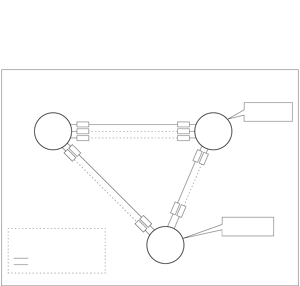
CHAPTER 6 ND-71762 (E)
Page 68
Issue 2
BASIC DATA ASSIGNMENT
2.2 Basic Data Assignment Procedure
This section explains “How to program necessary data associated with a CCIS network” using the following exam-
ple. Note that Node A is your office.
Figure 6-1 Example of a CCIS Network
• In this figure, five letters such as AAAAA, represent mounting location of CCT card or CCH card.
CCH1: BBBBB
Node A
CCH0: AAAAA
RT11
Centralized
Billing Office
CCH2: CCCCC
RT12
PC = 30
“830”
Node C
PC = 10
“810”
PC = 20
“820”
Node B
Centralized
Management Office
PC : Point Code
RT : Route
CCH : Common Channel Handler
“8xx” : Office Code
: Speech Line
: Signaling Line
TK4
TK5 CCH1’: EEEEE
CCH0’: DDDDD TK7
TK8
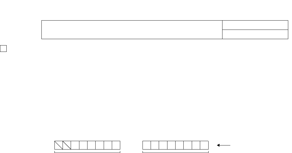
ND-71762 (E) CHAPTER 6
Page 69
Issue 2
BASIC DATA ASSIGNMENT
Since Point Code is used to identify each office in a CCIS network, any identical PCs are not allowed in the
same network. The following three kinds of point codes may be programmed in the system. The first PC, Orig-
inating Point Code (OPC), is mandatory. The remaining two Point Codes can be assigned as required.
• Originating Point Code (OPC): assigned by Indexes 180 and 181.
• Centralized Billing Point Code (DPC 0): assigned by Indexes 182 and 183.
• Centralized Management Point Code (DPC 1): assigned by Indexes 184 and 185.
1) Originating Point Code (OPC):
The OPC is a self-office code, which should be assigned without exception. 14 bits can be used for specifying
OPC. Note that available PC ranges from 1 to 16367 (PCs16368~16383 are used for Loop Back Test). Node
A whose OPC is 10, for example, should be assigned as follows.
2) Centralized Billing Point Code (DPC 0): Note 1
The DPC 0 is used when billing information of the PBX (Node A) should be sent to the Centralized Billing
Office. When DPC 0 is assigned as “20”, for example, billing information of Node A can be obtained at Node
B whose PC is 20. When this Centralized Billing feature is not necessary, skip these Indexes.
Note 1: Assign DPC 0 = 00 Hex to Centralized Billing Office.
3) Centralized Management Point Code (DPC 1): Note 2
The DPC 1 is used when system messages of the PBX (Node A) should be transmitted to the Centralized Man-
agement Center, from which all PBXs in the network can be managed. When DPC 1 is assigned as “30”, for
example, system messages can be automatically sent to Node C whose PC is 30 in this case.
Note 2: Assign DPC 1 = 00 Hex to Centralized Management Office.
STEP 1: Point Code & Miscellaneous Data Assignment COMMAND NAME
ASYD
0
b7
0
b6
0
b5
0
b4
1
b3
0
b2
1
b1
0
b0
0
b5
0
b4
0
b3
0
b2
0
b1
0
b0
Index 181 Index 180
PC 10
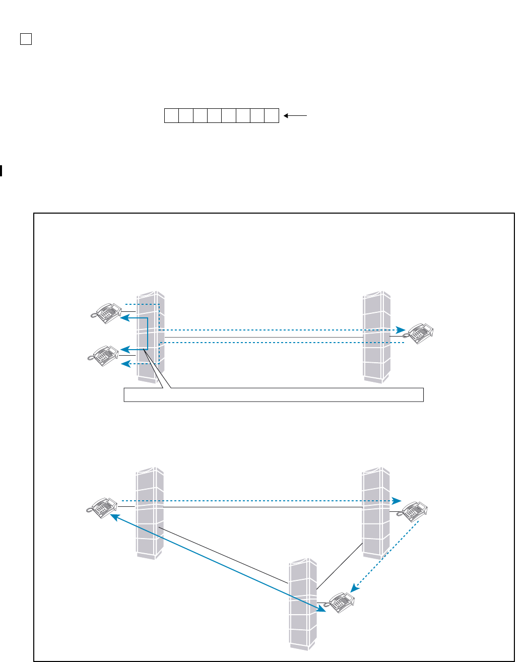
CHAPTER 6 ND-71762 (E)
Page 70
Issue 2
BASIC DATA ASSIGNMENT
Miscellaneous Data
1) Index 186:
b6 must be assigned as 1 (CCIS is in service). The remaining data should be determined depending on cus-
tomer’s requirements.
b0: 0/1 = CCIS Link Reconnection is not available/available.
When either of the two parties that are engaged in a Station-to-Station/Station-to-Trunk/Trunk-to-Trunk con-
nection via CCIS link transfers the call to another station, CCIS Link Reconnection will be provided. By es-
tablishing new link after the call transfer, the most proper routing can be provided for the two parties which
are eventually connected. Note 3, Note 4
0
b7
1
b6
0
b5
1
b4
0
b3
0
b2
1
b1
1
b0
Example (Index 186)
Station A
Station A
Station C
Station C
Station B
Station B
(1) Station A made a call to Station B
(1) Station A made a call to Station B
(2) Station B transferred the call to StationC
Link a
Link b
Link c
(3) Station B transferred the call to Station C
Node A Node B
Node A Node B
(4) Link Reconnection is provided between Station A and C, by using Link c.
At this time, LInk a and b are released.
(4) Link between Station A and C is reestablished, and Link between Node A and B is released.
Exmaple 1:
1. A call between Station A and B is established.
2. Station B transfers the call to Station C.
3. After connecting to Station C, Station B hungs up.
4. Link between Station A and C is reestablished. At this time Link between Node A and B is released.
Exmaple 2:
1. A call between Station A and Station B is established.
2. Station B transfers the call to Station C.
3. After connecting to Station C, Station B hungs up.
4. Link c (between Station A and C) is reestablished. at this time, Link a and b are released.
In the following cases, Link Reconnection is provided:
(3) Station B hungs up
(3) Station B hungs up
07/31/02
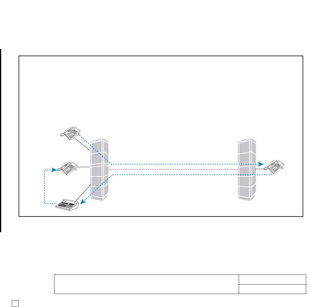
ND-71762 (E) CHAPTER 6
Page 71
Issue 2
BASIC DATA ASSIGNMENT
Note 3: When either of the two parties that are eventually connected (after a call transfer) is ATTCON, Link Re-
connection cannot be provided. (At this point, even if the ATTCON transfers the call to a station in the
same node and Station-to-Station connection is established, this function is not available.) In addition, this
function is not provided when either of the two parties that are eventually connected has a held party.
Note 4: In case a call is connected to the announcement trunks used for Delay Announcement-UCD service and
ACD Delay Announcement service, Link Reconnection function is not provided. (At this time, if the call is
eventually connected to UCD station/ACD agent position after the UCD station/ACD agent position be-
comes idle state, this function is provided.)
2) Index 187:Assign 00 Hex always.
Assign the following three routes for this feature:
• Speech Path Route (Traffic Route)
• Signaling Route
• Dummy Route (Flag Route).
STEP 2: Route Data Assignment COMMAND NAME
ARTD
Station A
Station D
ATTCON C
Station B
Station A made a call to Station B
Station B transferred the call to Attendant Console C
Node A Node B
Transfer to Station D
In the following case, Link Reconnection is not provided:
Example 3:
1. A call between Station A and Station B is established.
2. Station B transfers the call to ATTCON C.
3. After connecting to ATTCON C, Station B is released.
4. At this time, Link between Station A and ATTCON C is not reestablished.
5. ATTCON C transfers the call to Station D.
6. After connecting to Station D, ATTCON C is released.
7. Link Reconnection (between Station A and D) is not provided.
07/31/02
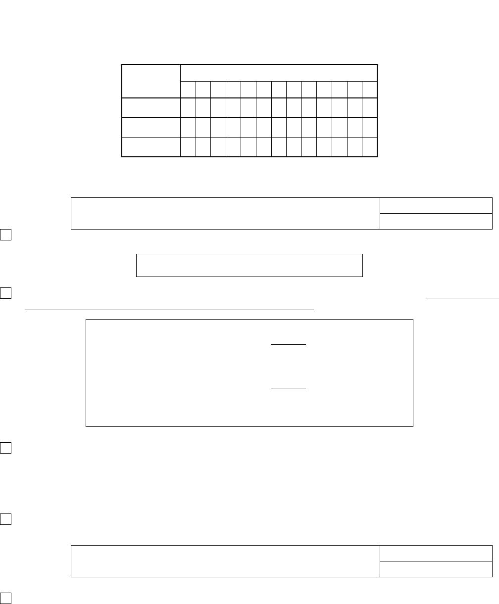
CHAPTER 6 ND-71762 (E)
Page 72
Issue 2
BASIC DATA ASSIGNMENT
Assign each route data in accordance with the table shown below. Note that data assignment in this table is a typical
example.
The other data than above should be set “0” (default data).
Assign Numbering Plan Data referring to the following example using the ANPD command.
Assign Special Access Code, using the ASPA command referring to the following example. Note that “LCR”
must be selected in the ASPA command to activate CCIS features.
Assign Reverse Numbering Plan Data using ARNP command. This assignment is required for speech path
route only (not for a signalling route number and a dummy route number). In the Open Numbering Network,
office code of the Self-node (including ACC for the originating call) must be assigned to RT0. The number of
digits for office code must be identical in the network. This data is used for originating office code display on
SMDR, Dterm, DESK CONSOLE/ATT and so on.
In addition to these commands, other commands related to “LCR” such as AFRS, AUNE, AOPR and AMND
are required. For more detailed information on the LCR feature, see the “Feature Programming Manual”.
Assign route restriction data as to the already assigned route as required.
ROUTE CDN
24567813152830434950
Speech 2234120121010/11
Signaling 22041001307000
Dummy 0004101000000
STEP 3: Numbering Plan Data COMMAND NAME
ANPD & ASPA
TN: 1 1st DC: 8 CI: N/H NND: 3 BLF 0
(for accessing Node B)
TN: 1 ACC: 820 CI: N/H SRV: LCR
RT: 31 2nd DT: 0 AH: 0 SUB: 0
(for accessing Node C)
TN: 1 ACC: 830 CI: N/H SRV: LCR
RT: 31 2nd DT: 0 AH: 0 SUB: 0
Note: In this example, RT31 is dummy route.
STEP 4: Restriction Data COMMAND NAME
ARSC & ARRC
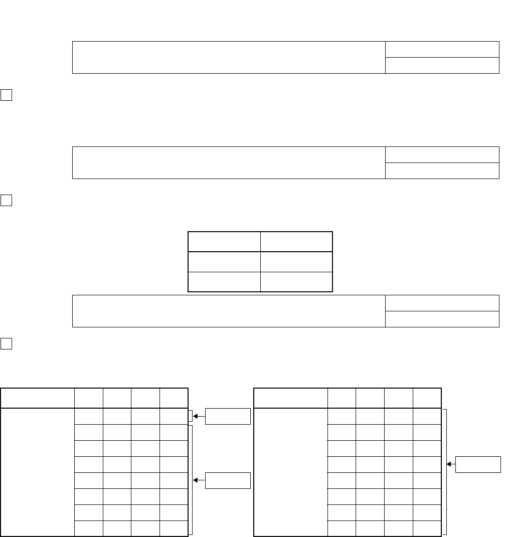
ND-71762 (E) CHAPTER 6
Page 73
Issue 2
BASIC DATA ASSIGNMENT
Assign trunk(s) to desired LENs using the ATRK command. In this instance, the MBTK command is not re-
quired for the signaling trunk.
Note: See 2.1 “Port Allocation and Related Command”.
Assign the associated PC on an RT (for speech path) number basis. In the case of the example illustrated in
Figure 6-1, appropriate data is as follows.
Assign the location of the CCH using the ACSC command. The following is sample data assignment. In this
sample, Node A is equipped with three DTI cards. Note that if the system employs one CCIS link, enter the
same data in CSCG130 and CSCG131.
Note 1: In the case of actual data entry, enter corresponding LEN numbers instead of letters such as “AAAAA”.
Note 2: Refer to 2.1 “Port Allocation and Related Command”.
STEP 5: Assignment of Trunk Data COMMAND NAME
ATR K & MBT K
STEP 6: Assignment of DPC COMMAND NAME
ADPC
RT PC
11 20
12 30
STEP 7: Assignment of Common Channel Signaling Controller (CSC) COMMAND NAME
ACSC
CSCG MG U G CICG CSCG MG U G CICG
130
(Basic/
Primary Route)
AA A AA 0 CCH 0
131
(Alternate
Route)
CCCCC0
BBBBB1 CCCCC1
BBBBB2 CCCCC2
BBBBB3 CCCCC3 CCH 2
BBBBB4 CCH 1 CCCCC4
BBBBB5 CCCCC5
BBBBB6 CCCCC6
BBBBB7 CCCCC7
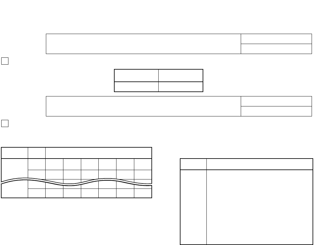
CHAPTER 6 ND-71762 (E)
Page 74
Issue 2
BASIC DATA ASSIGNMENT
Assign the CSCG for Basic/Primary Route. The odd numbered CSCG for Alternate Route assignment.
Assign Circuit Identification Codes (CICs), which correspond to “trunk” number. Although trunk number and
the CIC number may not be identical, the same CIC number must be given to one speech line between two
nodes as illustrated in Figure 6-2.
STEP 8: Assignment of Circuit Identification Code1 COMMAND NAME
ACIC1
PC CSCG
20 130
STEP 9: Assignment of Circuit Identification Code2 COMMAND NAME
ACIC2
PC CIC LEN Relationship between CICG and CIC
20 1XXXXXX CICG CIC (1 ~ 999)
2XXXXXX 0 81624–992
1 1 91725–993
NXXXXXX 2 2101826–994
3 3 11 19 27 – 995
4 4 12 20 28 – 996
5 5 13 21 29 – 997
6 6 14 22 30 – 998
7 7 15 23 31 – 999
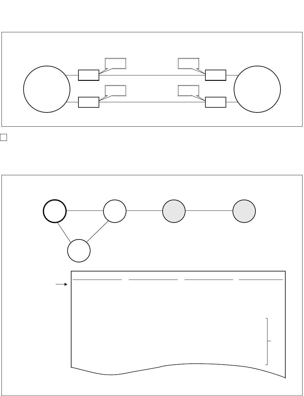
ND-71762 (E) CHAPTER 6
Page 75
Issue 2
BASIC DATA ASSIGNMENT
Figure 6-2 CIC Number Assignment
When your network includes a tandem connection, be sure to assign PCs of the all nodes in the network. As
Figure 6-3 “Example of a CCIS Network (Tandem)” shows, assign PCs 40 and 50 in addition to that of Node
B (PC=20), which is directly connected to Node A.
Figure 6-3 Example of a CCIS Network (Tandem)
The CIC number must be identical between two nodes as shown below.
TK4
CIC=1
CCIS line
TK5
CIC=2
CCIS line
TK7
CIC=1
TK8
CIC=2
Node A Node B
CCH0
CCH1
CCH0’
CCH1’
PC CSCG CIC LEN
20 130 1 xxxxxx
(for Node B) 2 xxxxxx
N xxxxxx
40 130 1 –
(for Node D) 2 –
N–
50 130 1 –
(for Node E) 2 –
A sample office data assignment sheet for Node A is as follows.
PC=10 PC=20 PC=40 PC=50
PC=30
Node A Node B Node D Node E
Node C
Sample Office Data Assignment for Node A
ACIC/ACIC2
~~
~~
Note
command
Note: Press the “SPACE” bar to skip LEN and press the “RETURN” key.

CHAPTER 6 ND-71762 (E)
Page 76
Issue 2
BASIC DATA ASSIGNMENT
2.3 FCCS Data Assignment Procedure
This section explains the basic data assignment to be required when CCIS services are activated in an FCCS Net-
work. Feature and Specifications Manual shows the CCIS services allowed in an FCCS Network. See “FCCS Net-
work System Manual” and “Office Data Specification Manual” for details.
Note: This data setting is necessary for the following services since they may be provided to FCCS system.
•CENTRALIZED MAINTENANCE-CCIS [C-167]
•NUMBER PORTABILITY-CCIS [N-46]
For details of this feature, see “Feature Programming Manual”.
When the above features are used, there are conditions of FCCS data assignment as described below.
1. When connecting the stand-alone PBX, non-FCCS system, with another FCCS Group (FUG) or
NEAX2000IPS,
(a) The system must be the NCN.
(b) The system is programmed as the FCCS Network configured by one NCN only.
(c) Use the NDM of the system to program the network data.
2. When connecting the NEAX2400IPX system and the NEAX2000IPS system, CIC (Circuit Identification
Code) =1 should always be assigned using ACIC2 command.
3. Common Channel Handler (CCH) location of the Common Channel Signaling Controller Group (CSCG) data
(CCH location per CSCG) must be programmed against each PC of the connected IPX or IPS system using
ACSCL command.
4. PCs (Point Codes) in the network through FUGs and IPS are programmed as unique (All PCs used in the net-
work are different).
For the system to be connected with the next system via CCIS link or the large sized network, this assignment
is basically recommended.
5. The CCH to be used is selected as follows.
when the call is processed using the speech line (Bch), the outgoing/incoming route (Logical Route: LRT)
decides CCH.
LRT → PC → CSCG → CCH
when the call is processed without speech line (Bch) - inter-office service such as CALL BACK, MES-
SAGE WAITING service, MCI, etc., the called party’s number or PC of the destination decides CCH.
(a) the called party’s number → LRT → PC → CSCG → CCH
(b) PC → CSCG → CCH
when logging into IPS or IPX in the remote FUG from the Centralized-MAT, PC of the node to be logged
in decides CCH.
(a) IPS
PC → CSCG → CCH
(b) IPX in Remote FUG
FUG + FPC → PC → CSCG → CCH
*FUG and FPC to be designated for logged-in node are converted automatically within the system.
1
2
3

ND-71762 (E) CHAPTER 6
Page 77
Issue 2
BASIC DATA ASSIGNMENT
Note that the data to be required varies depending on the node.
(a) Node providing CCIS trunk
See the basic data assignment procedure in the previous section
STEP 1: ASYD - Assign the unique PC for the self-node (OPC).
STEP 2: ARTD - Assign the CCIS route data.
STEP 3: ATRK - Assign the CCIS trunk data.
STEP 4: MBTC - Assign IDLE status of trunks by designating Route Number and Trunk Number.
STEP 5: ADPC - Assign the destination PC (Point Code) on RT (for speech path) number basis for all the nodes
in the network.
STEP 6: ACSC - Assign the location of the CCH in CSCG (Common Channel Signaling Controller Group).
STEP 7: ACIC1 - Assign CSCG for Basic/Primary Route. The odd numbered CSCG for Alternate Route assign-
ment.
STEP 8: ACIC2 - Assign CICs (Circuit Identification Codes) corresponding to trunk number. Although trunk
number and the CIC may not be identical, the same CIC must be given to one speech line between two
nodes. Be sure to assign PCs of all nodes in the network corresponding to ADPC/ACIC1 command.
Note 1: When connecting the NEAX2400IPX system and the NEAX2000IPS system, CIC (Circuit Identification
Code) =1 should always be assigned using ACIC2 command.
STEP 9: ARNPL - Assign the access code for LCR/LCRS as assigned in ASPAN associated with the logical
routes for each external trunk assigned in ARTD/ ARTDN command.
STEP 10: AMND - Assign the number of necessary digits to be received by the Register (ORT/IRT) circuit.
Note 2: The MND is the total number of ACC + Telephone Number.
(b) Node using the CCIS trunk in the remote node via FCCS line
STEP 1: ASYD - Assign the unique PC of self-node (OPC).
STEP 2: ADPCL - Assign the destination Point Code (PC) on LGRT (for speech path) number basis for all the
nodes in the network.
STEP 3: ACSCL - Assign the location of the CCH and FPC of the node which accommodates CCIS trunk in
CSCG (Common Channel Signaling Controller Group) for all nodes in the network.
Note 1: CSCG no. assigned in ACSC is not available.
STEP 4: ACIC1 - Assign the CSCG for Basic/Primary Route. The odd numbered CSCG for Alternate Route as-
signment.
STEP 5: ARNPL - Assign the access code for LCR/LCRS as assigned in ASPAN associated with the logical
routes for each external trunk assigned in ARTD/ ARTDN command.
STEP 6: AMND - Assign the number of necessary digits to be received by the Register (ORT/IRT) circuit.
Note 2: The MND is the total number of ACC + Telephone Number.

CHAPTER 6 ND-71762 (E)
Page 78
Issue 2
BASIC DATA ASSIGNMENT
(c) NCN (Network Controlling Node)
STEP 1: ALRTN - Assign the Logical Route Numbers to all external trunks used in the network. Assign unique
Logical Route Numbers to the whole routes for external trunks on the network (including COT, DAT,
dummy route, etc.) using this command. When the network accommodating multiple FCCS Networks
(FUGs) and/or NEAX7400ICS M100IMX is established, the data must be set at the NCN in each FUG
and is to be set for every external route in all the nodes.
STEP 2: ARSCN - Assign route restriction information according to the Route Restriction Class (RSC) of the
Logical Route Number in the network.
STEP 3: ANPDN - Assign the minimum number of digits needed to determine the service (Telephone Number)
which is required to the first digit received (pre-translation).
STEP 4: ASPAN - Assign the special access code. Assign Abbreviated Digit Code (ADC) for connected FUGs
using AEADN command.
STEP 5: AFRSN - Assign the NPC (Number Pattern Code) and OPR (Outgoing Route Selection Number) for
dummy route number.
STEP 6: AOPRN - Assign the routes and in what order these routes will be selected corresponding to the data
assigned by AFRSN command.
STEP 7: ARNPL - Assign the access code for LCR/LCRS as assigned in ASPAN associated with the logical
routes for each external trunk assigned in ARTD/ ARTDN command.
STEP 8: AMND - Assign the number of necessary digits to be received by the Register (ORT/IRT) circuit.
Note 2: The MND is the total number of ACC + Telephone Number.
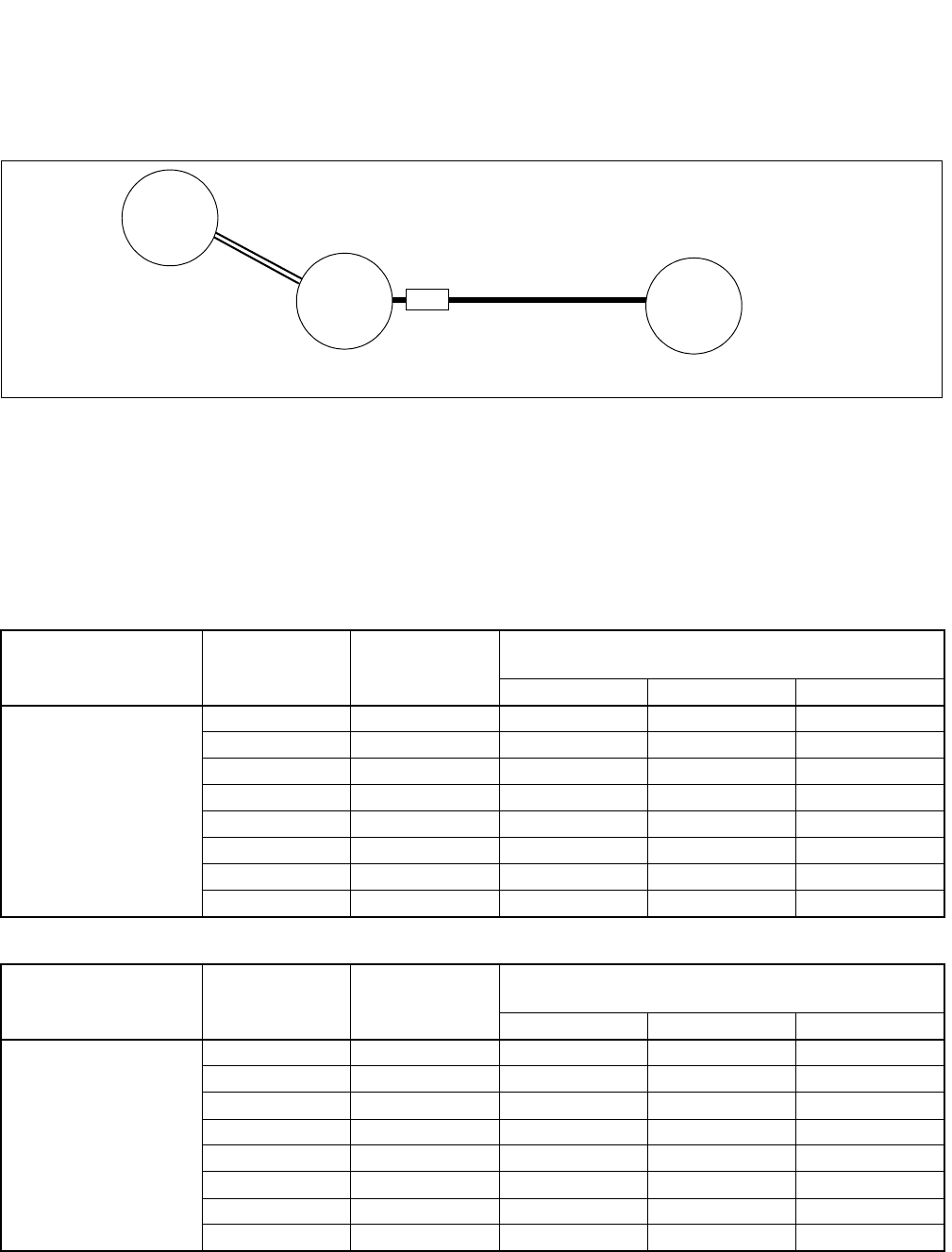
ND-71762 (E) CHAPTER 6
Page 79
Issue 2
BASIC DATA ASSIGNMENT
Data Assignment of Network through FCCS Groups and NEAX7400ICS M100IMX
When CCH in the remote node is used via CCIS line, the data assignment shown below is required for inter-office
service.
In the example figure, FPC1(PC1) must be set the following data for inter-office service activated between
FPC1(PC1) and PC3 (provided that CCIS data assignment is already programmed at FPC2(PC2) and PC3).
STEP 1: ADPCL - Assign PC for each speech path (Logical Route).
Example: LGRT=1, PC3
STEP 2: ACSCL - Assign the location of CCH in CSCG (Common Channel Signaling Controller Group) and FPC
node where accommodates CCH.
• Basic/Primary Route
• Alternate Route
CSCG
(2-254: even
number)
GROUP
(CIC Group
No.)
FPC
COMMON CHANNEL SIGNALING
CONTROLLER LENS (CCH)
MG U G
2
0200020
1200020
2200020
3200020
4200020
5200020
6200020
7200020
CSCG
(2-254: odd
number)
GROUP
(CIC Group
No.)
FPC
COMMON CHANNEL SIGNALING
CONTROLLER LENS (CCH)
MG U G
3
0200020
1200020
2200020
3200020
4200020
5200020
6200020
7200020
Example
FPC1
PC1
IMX (NCN)
Office Code: 76
FPC2
PC2
PC3
FCCS
IMX (LN)
CCIS
Office Code: 75
LGRT1
CCH:00020
ACC:75 M100IMX

CHAPTER 6 ND-71762 (E)
Page 80
Issue 2
BASIC DATA ASSIGNMENT
STEP 3: ACIC1 - Allocate CSCG no. against the remote node in the network.
Assign the point code assigned in ADPCL in PC parameter and CSCG no. (even number) for basic route
assigned in ACSCL to CSCG parameter.
*CSCG no. for alternate route assignment is not necessary.
Example: PC=3, CSCG=2
STEP 4: ARNPL - Assign the access code for speech route (Logical Route)
*The assignment for signal route and dummy route is not necessary.
Example: LGRT=1, ACC=75
STEP 5: ARNP -Assign the self-office code to RT0 in the open numbering network.
This number is used for Calling number identification on SMDR, Dterm, DESK CONSOLE, ATTEN-
DANT CONSOLE, and inter-office services.
Example: RT=0, ACC=76

ND-71762 (E) CHAPTER 7
Page 81
Issue 2
CCIS SERVICE FEATURES
CHAPTER 7 CCIS SERVICE FEATURES
1. GENERAL
Table 7-1 shows the list of CCIS service features. As for details of service features which are shown in Table 7-1,
refer to “Feature Programming Manual” that explains each service feature by the following items.
• General Description
• Operating Procedure
• Service Conditions
• Interactions
•Programming
(1) General Description
(2) Operating Procedure
This item explains the procedure to be followed for receiving a specific service feature concerned. When testing
a service feature, perform installation test work steps by referring to this item.
(3) Service Conditions
This item explains the functional outline of a specific service feature concerned and the matter of caution (hard-
ware requirements, etc.) related to performance of that service feature. It is recommended that these items be
referred to for more extensive knowledge of the service feature concerned.
(4) Interactions
This item explains the service conditions or hardware requirements when using together with other service fea-
tures.
(5) Programming
This item explains the procedure of assigning various kinds of data required for performance of a specific ser-
vice feature concerned. When recording necessary data into Data Programming Sheets provided in the “Office
Data Specifications”, make data entry by referring to this item.

CHAPTER 7 ND-71762 (E)
Page 82
Issue 2
CCIS SERVICE FEATURES
Table 7-1 List of Service Features for CCIS (1/2)
Note: This feature is available in North America only.
SERVICE CODE No. SERVICE FUNCTION NAME REMARKS
A-45 Attendant Camp-On with Tone Indication - CCIS
A-46 Attendant Controlled Conference - CCIS
A-71 Automatic Recall - CCIS
A-87 Automatic Number Identification (ANI) - CCIS Note
A-126 ANI - CCIS (16 digit) Note
B-9 Busy Verification - CCIS
B-10 Brokerage Hotline - CCIS
C-44 Call Back - CCIS
C-45 Call Forwarding - All Calls - CCIS
C-46 Call Forwarding - Busy Line - CCIS
C-47 Call Forwarding - Don’t Answer - CCIS
C-48 Call Forwarding - Intercept - CCIS
C-49 Call Forwarding - Override - CCIS
C-50 Call Transfer - All Calls - CCIS
C-51 Called Station Status Display - CCIS
C-52 Calling/Called Number Display - CCIS
C-53 Call Processing Indication - CCIS
C-54 Call Transfer - Attendant - CCIS
C-55 Centralized Billing - CCIS
C-56 Centralized Day/Night Mode Change - CCIS
C-57 Centralized System Management Report - CCIS
C-58 Consultation Hold - All Calls - CCIS
C-94 Call Forwarding Assignment - Attendant - CCIS
C-163 CCIS Networking via IP
C-167 Centralized Maintenance - CCIS
D-70 Deluxe Traveling Class Mark - CCIS
D-71 Dial Access to Attendant - CCIS
D-72 Digital Display - Station - CCIS
D-73 Digital Display - Trunk - CCIS
D-74 Direct-In - Termination - CCIS
D-75 Distinctive Ringing - CCIS
D-76D Do not Disturb - Dterm - CCIS
D-91 Dialed Number Display - Recall - CCIS Note
D-93D Dual Hold Dterm - CCIS
E-8 Executive Right-of-Way - CCIS
E-9 Elapsed Time Dispaly - CCIS
E-20 E911 - ANI Unified Number of Digits - CCIS Note
F-12 Flexible Numbering of Stations - CCIS
H-10D Hands-Free Answerback - Dterm - CCIS
H-11 House Phone - CCIS
H-12 Hotline - CCIS

ND-71762 (E) CHAPTER 7
Page 83
Issue 2
CCIS SERVICE FEATURES
Table 7-1 List of Service Features for CCIS (2/2)
Note 1: This feature is available in North America only.
Note 2: This feature is not available in North America.
SERVICE CODE No. SERVICE FUNCTION NAME REMARKS
I-16 Incoming Call Identification - CCIS
I-17 Individual Attendant Access - CCIS
I-18 Inter-Position Transfer - CCIS
I-19 Individual Trunk Access - CCIS
L-25 Look Ahead Routing - CCIS Note 1
L-29 LDN Night Connection - CCIS
M-34 Message Reminder - CCIS
M-34D Message Reminder -Dterm - CCIS
M-35 Message Waiting Lamp Setting - Attendant - CCIS
M-36 Message Waiting Lamp Setting - Station - CCIS
M-37 Miscellaneous Trunk Access - CCIS
M-38 Miscellaneous Trunk Restriction - CCIS
M-40 Multiple Call Forwarding - All Calls - CCIS
M-41 Multiple Call Forwarding - Busy Line - CCIS
M-42 Multiple Call Forwarding - Don’t Answer - CCIS
M-43 Multiple Console Operation - CCIS
M-67 Message Center Interface - CCIS
N-15 Night Connection - Fixed - CCIS
N-16 Night Connection - Flexible - CCIS
N-36 Name Display - OAI - CCIS Note 2
N-37 Name Display - System - CCIS
N-38 Node Number Suppression - CCIS Note 2
N-46 Number Portability - CCIS
O-11 Off-Hook Queuing - CCIS
O-12 Outgoing Trunk Queuing - CCIS
P-28 Paging Access - CCIS
R-22 Restriction from Outgoing Calls - CCIS
S-52 Serial Call - CCIS
S-53D Service Display - Dterm - CCIS
S-55 Single-Digit Station Calling - CCIS
S-56 Station-Controlled Conference - CCIS
S-57 Station-to-Station Calling - CCIS
S-58 Station-to-Station Calling -Operator Assistance - CCIS
S-59 Step Call - CCIS
S-73 Supervisory Call - CCIS
T-26 Toll Restriction - 3/6-digit - CCIS
T-27 Trunk Answer from Any Station - CCIS
U-5 Uniform Numbering Plan - CCIS
V-7 Voice Call - CCIS

CHAPTER 8 ND-71762 (E)
Page 84
Issue 2
MAINTENANCE PROCEDURE
CHAPTER 8 MAINTENANCE PROCEDURE
1. GENERAL
This chapter describes the system messages related to basic CCIS Network (not including messages related to Net-
work through FCCS Groups and NEAX2000IPS, procedures for CCIS Line operating mode control, and procedures
for extracting/inserting the circuit cards for CCIS while the system is in service. For other matters, refer to the Sys-
tem Operation and Maintenance Manual.
2. SYSTEM MESSAGES
System messages are displayed during routine diagnosis, system operation status controlling and fault occurrences.
This paragraph explains the following items for each system message related to CCIS:
(1) Meaning
(2) Related System Message
(3) Example of Printout
(4) Message Detail Data Note 1
(5) Diagnostic Work Note 2
For those system messages which are not explained in this chapter, refer to the System Operation and Maintenance
Manual.
Note 1: Paragraph 2.2: “Technical Terms for Explaining Message Detail Data” explains technical terms used in
the explanation.
Note 2: Paragraph 2.3: “How to Proceed with Diagnostic Work from System Message” explains how to perform
diagnosis.

ND-71762 (E) CHAPTER 8
Page 85
Issue 2
MAINTENANCE PROCEDURE
2.1 The Relationship between System Messages and Lamp Indications
When the system has detected a fault, the corresponding system message is displayed, at the same time, the related
lamp on the TOPU.
Table 8-1 shows the relationship between system messages and default lamp indications.
Note: ×: Default Lamp Indication.
Table 8-1 System Messages and Lamp Indications on TOPU
SYSTEM MESSAGE LAMP ON THE TOPU
No. NAME MJ MN SUP PWR
13-A CCH Clock Failure ×
13-B CCH C-Level Infinite Loop
(Permanent) ×
13-C CCH C-Level Infinite Loop (Temporary) ×
13-D CCH Lock Up Failure
(Permanent) ×
13-E CCH Lock Up Failure
(Temporary) ×
13-F CCH B-Level Infinite Loop
(Permanent) ×
13-G CCH B-Level Infinite Loop (Temporary) ×
13-H CCS Link Failure (Permanent) ×
13-I CCS Link Failure (Temporary)
13-J Restoration from CCS Link
Failure
13-K CCH Reset Interrupt Failure ×
17-A CCH MBR Key Turn ON
17-B CCH MBR Key Turn OFF

CHAPTER 8 ND-71762 (E)
Page 86
Issue 2
MAINTENANCE PROCEDURE
2.2 Technical Terms for Explaining Message Detail Data
Some technical terms are used to explain the detail data in each system message and circuit card information. Some
technical terms and the circuit card mounting information, which are used in common to explain the various system
message, are shown below.
Phase 1 Restart Processing Execution
All the processing being executed is suspended, and the system operations are allowed to restart from the monitor
program without any hardware controlling involved. More specifically, the processing on calls being handled by the
programs are abandoned, and all the connections already established are maintained.
Phase 3 Restart Processing Execution
By initializing each PM (Line/Trunk circuit card), the following processes are executed:
• Forcibly releasing the calls connected with the initialized Lines/Trunks.
• Releasing the related links.
Data for Analysis by NEC Engineers
These message detail data are used by NEC engineers when analyzing faults, and thus they are not used in ordinary
fault repair works.
When a fault is complicated one, the data are used when reporting the fault to NEC or when NEC engineers inquire
about the fault.
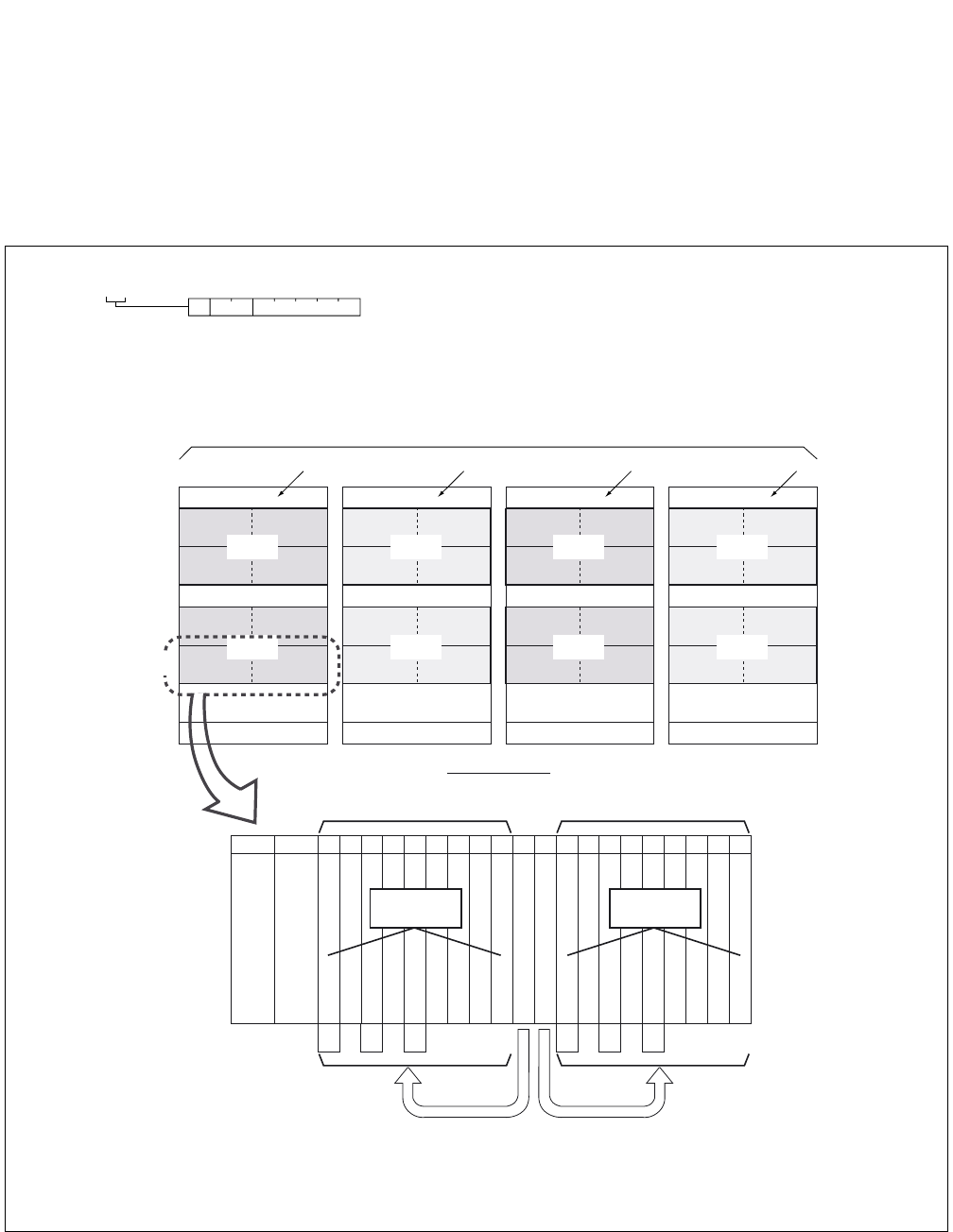
ND-71762 (E) CHAPTER 8
Page 87
Issue 2
MAINTENANCE PROCEDURE
2.2.1 Circuit Card Mounting Information
(1) Circuit Card Mounting Information
Accommodated location information of each circuit card is described by a hexadecimal number.
Figure 8-1 Circuit Card Mounting Location (1/2)
FRONT VIEW
TOPU
IMG0
FANU
BASEU
LPM
U2 U3
U0 U1
U2 U3
U0 U1
MG01
MG00
TOPU
IMG2
FANU
BASEU
DUMMY
U2 U3
U0 U1
U2 U3
U0 U1
MG05
MG04
TOPU
IMG3
FANU
BASEU
DUMMY
U2 U3
U0 U1
U2 U3
U0 U1
MG07
MG06
TOPU
IMG1
FANU
BASEU
TSWM
U2 U3
U0 U1
U2 U3
U0 U1
MG03
MG02
PIM3
PIM2
PIM1
PIM0
00 02 04 05 06 07 08 09 10 11 12 13 14 15 16 17 18 19 20 21 22 23
16 16 16 16 16 16 32 32 32 16 16 16 16 16 16 32 32 32
MUX (PH-PC36) 0
MUX (PH-PC36) 1
192 TS
PWR
PWR
Unit Number (U = 0/2) Unit Number (U = 1/3)
Control Control
1-IMG/4-IMG system
192 TS
16 16 16 16 16 16
Number
of
Time Slots
Slots No.
PIM
(16)(16)
(a) MG and Unit configuration
1 : XX00 00
MG: Module Group Number
U: Unit Number
G: Group Number
MG
UG
LP0 LP2 LP4 LP6
Note: LP (Local Partition Number),
MG (Module Group Number)
U (Unit Number)
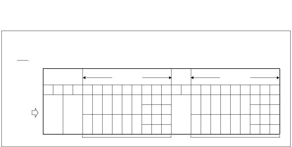
CHAPTER 8 ND-71762 (E)
Page 88
Issue 2
MAINTENANCE PROCEDURE
Figure 8-1 Circuit Card Mounting Location (2/2)
(b) Group Configuration
PIM
00 01 02 03 04 05 06 07 08 09 10 11 12 13 14 15 16 17 18 19 20 21 22 23
01 03 05 07 09 11
15 19 23
01 03 05 07 09 11
15 19 23
14 18 22 14 18 22
00 02 04 06 08 10
13 17 21
00 02 04 06 08 10
13 17 21
12 16 20 12 16 20
UNIT = 0, 2 UNIT = 1, 3
LINE/TRUNK
LINE/TRUNK
SLOT No.
GROUP No.

ND-71762 (E) CHAPTER 8
Page 89
Issue 2
MAINTENANCE PROCEDURE
2.3 How to Proceed with Diagnostic Work from System Message
The diagnostic procedure after seeing a system message is illustrated in Figure 8-2. Judge whether the fault status
coincides with the indicated status, following the sequence beginning with START.
STEP 1: Judge whether the fault coincides with the fault status (1).
STEP 2: If the fault status does coincide, the fault is indicated by (2). Repair the fault according to paragraph ×.
×. × as shown by (3). Otherwise, proceed to (4).
STEP 3: Perform the work indicated by (4).
The result of the work (4) is broken down as indicated by (5).
STEP 4: Make a judgment as to whether the result of work (4) coincides with the status indicated by (6).
If so, the fault is indicated either by (7) or by (2’). If not, proceed to the next step.
STEP 5: Perform the work indicated by (4’), and if the result of the work is the same as the status indicated, the
fault is indicated by (2’’).
If the fault repair work indicated by (2’’) affects another normal line, recheck the work as indicated by
(8).
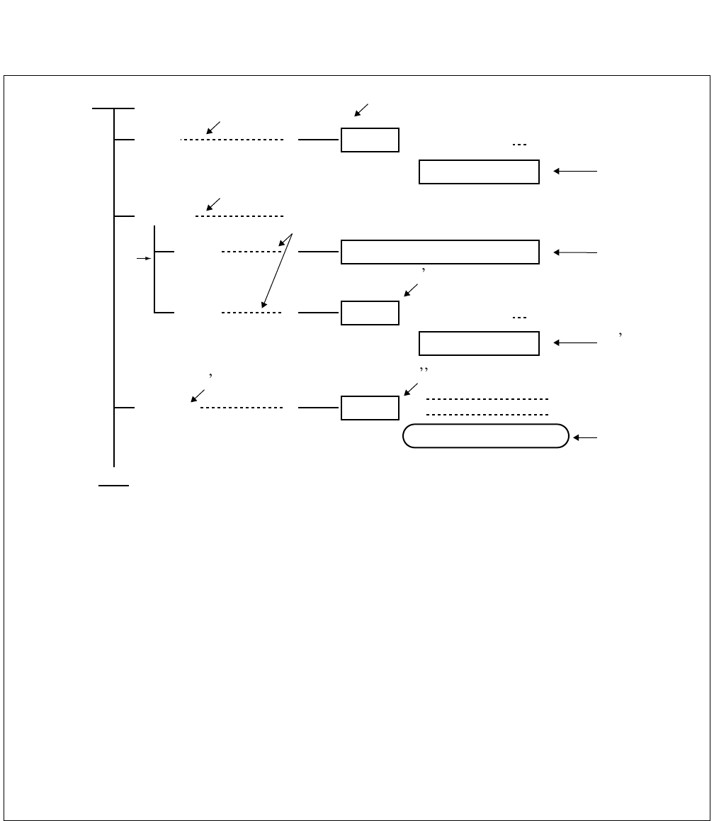
CHAPTER 8 ND-71762 (E)
Page 90
Issue 2
MAINTENANCE PROCEDURE
Figure 8-2 Example of Diagnostic Work Items and Symbols
START
END
When
(1)
(2)
FAULT : It is the fault of
paragraph ×. ×. ×(3)
(7)
Perform
When
(6)
FAULT SUPERVISION
When
(2 )
FAULT : It is the fault of
paragraph ×. ×. ×(3 )
(8)
Perform
(4 )
FAULT :
CHECK OF WORK
(4)
(2 )
(5)
Note: (1): Judgment of faulty status
(2): When the fault status coincides with the indication, the cause for the fault is indicated.
(3): Operating items for diagnosis
(4): When the operating method is unknown, refer to the Operations and Maintenance Manual.
(5): Branching as the result of the operation (4)
(6): Judgment of the status as the result of the operation
(7): If, as a result of a fault diagnosis, the faulty condition cannot be reproduced and is judged to be
temporary, this information is displayed.
In this case, clear the indicated alarm and the system message using the RALM command and
place the system under supervision to see if the same fault recurs.
(8): While a fault repair is in progress, perform various operations such as system changeover, ini-
tialization, etc. When such operations are performed, they affect the normally operating station
lines, attendant consoles, trunks, etc. in the form of momentary disconnection, speech interrup-
tion, forced release of calls in progress, etc.
By comparing the urgency of the required fault repair with the above-mentioned effects on the
lines, trunks, etc., determine the proper timing for performing the necessary recovery work.

ND-71762 (E) CHAPTER 8
Page 91
Issue 2
MAINTENANCE PROCEDURE
2.4 System Messages
“13-A”: CCH Clock Failure
(1) Meaning
The system message “13-A” indicates that, a clock down failure has occurred to the CCH circuit. When this
system message is indicated, the related CCH/CCT circuit card is placed into make-busy state.
(2) Related System Message
None
(3) Example of Printout
(4) Message Detail Data
*a: Accommodated location of the CCH detected the failure.
(Refer to paragraph 2.2.1)
(5) Diagnostic Work
Refer to Paragraphs 3.3 or 3.4.
1: XX 00
*a
SYSTEM MESSAGE 13-A [SUP] CCH CLOCK FAILURE
NEC TOKYO MAY 14 10:30
LP00-0-ACT
1: 0100 0000 0000 0000 2: 0000 0000 0000 0000 3: 0000 0000 0000 0000
4: 0000 0000 0000 0000 5: 0000 0000 0000 0000 6: 0000 0000 0000 0000
7: 0000 0000 0000 0000 8: 0000 0000 0000 0000 9: 0000 0000 0000 0000
MG U G
MG:
U:
G:
Module Group
Unit
Group

CHAPTER 8 ND-71762 (E)
Page 92
Issue 2
MAINTENANCE PROCEDURE
“13-B”: CCH C-Level Infinite Loop Failure. (Permanent)
(1) Meaning
The system message “13-B” indicates that C-level infinite loop (Note) of the PM (Port Microprocessor) within
the CCH/CCT circuit card has occurred more than 15 times within an hour. When this fault has occurred, the
specific PM is placed into make-busy state and restarted. (The fault counter is “0” at the beginning of every
one hour.)
Note: This is a state in which the C-Level Monitor Program (the program which detects off-hook/on-hook related
to lines/trunks) repeats a specific routine. The number of times to be repeated is counted by the error-
counter corresponding to the CPU.
(2) Related System Message
When the C-level infinite loop failure occurs less than 16 times, the Phase 1 restart or Phase 3 restart is exe-
cuted at the specific PM of CCH/CCT card and the system message “13-C” is output.
(3) Example of Printout
(4) Message Detail Data
(a) Accommodated location of the CCH detected the failure.
(Refer to paragraph 2.2.1)
SYSTEM MESSAGE 13-B [SUP] CCH C-LEVEL INFINITE LOOP FAILURE (PERMANENT)
NEC TOKYO MAY 14 10:30
LP00-0-ACT
1:
XX
00 0000 0000 0000 2: 0000 0000 0000 0000 3: 0000 0000 0000 0000
4: 0000 0000 0000 0000 5: 0000 0000 0000 0000 6: 0000 0000 0000 0000
7: 0000 0000 0000 0000 8: 0000 0000 0000 0000 9: 0000 0000 0000 0000
(a)
MG U G
MG:
U:
G:
Module Group
Unit
Group

ND-71762 (E) CHAPTER 8
Page 93
Issue 2
MAINTENANCE PROCEDURE
(5) Diagnostic Work
START
END
When system message 13-B is displayed, Turn ON the MBR Key on the CCH/CCT circuit card,
and then set the MB key ON→OFF.
System message 13-B is displayed FAULT : CCH/CCT circuit card is faulty.
System message 13-B is not SUPERVISION FAULT
displayed
Paragraphs 3.3 or 3.4

CHAPTER 8 ND-71762 (E)
Page 94
Issue 2
MAINTENANCE PROCEDURE
“13-C”: CCH C-Level Infinite Loop Failure (Temporary)
(1) Meaning
The system message “13-C” indicates that C-level infinite loop for PM (Port Microprocessor) within a CCH/
CCT circuit card has occurred less than 16 times within an hour. When the number of the fault occurrence time
is less than 8, the Phase 1 restart is executed.
If the number of fault occurrence time is 8 to 16, the Phase 3 restart is executed.
(2) Related System Message
When the C-level infinite loop failure occurs more than 15 times, the specific PM of CCH/CCT is placed into
make-busy state and the system message “13-B” is output.
(3) Example of Printout
(4) Message Detail Data
(a) Accommodated location of the CCH detected the fault.
(Refer to paragraph 2.2.1)
SYSTEM MESSAGE 13-C [SUP] CCH C-LEVEL INFINITE LOOP FAILURE (TEMPORARY)
NEC TOKYO MAY 14 10:30
LP00-0-ACT
1:
XX
00 0000 0000 0000 2: 0000 0000 0000 0000 3: 0000 0000 0000 0000
4: 0000 0000 0000 0000 5: 0000 0000 0000 0000 6: 0000 0000 0000 0000
7: 0000 0000 0000 0000 8: 0000 0000 0000 0000 9: 0000 0000 0000 0000
(a)
MG U G
MG:
U:
G:
Module Group
Unit
Group
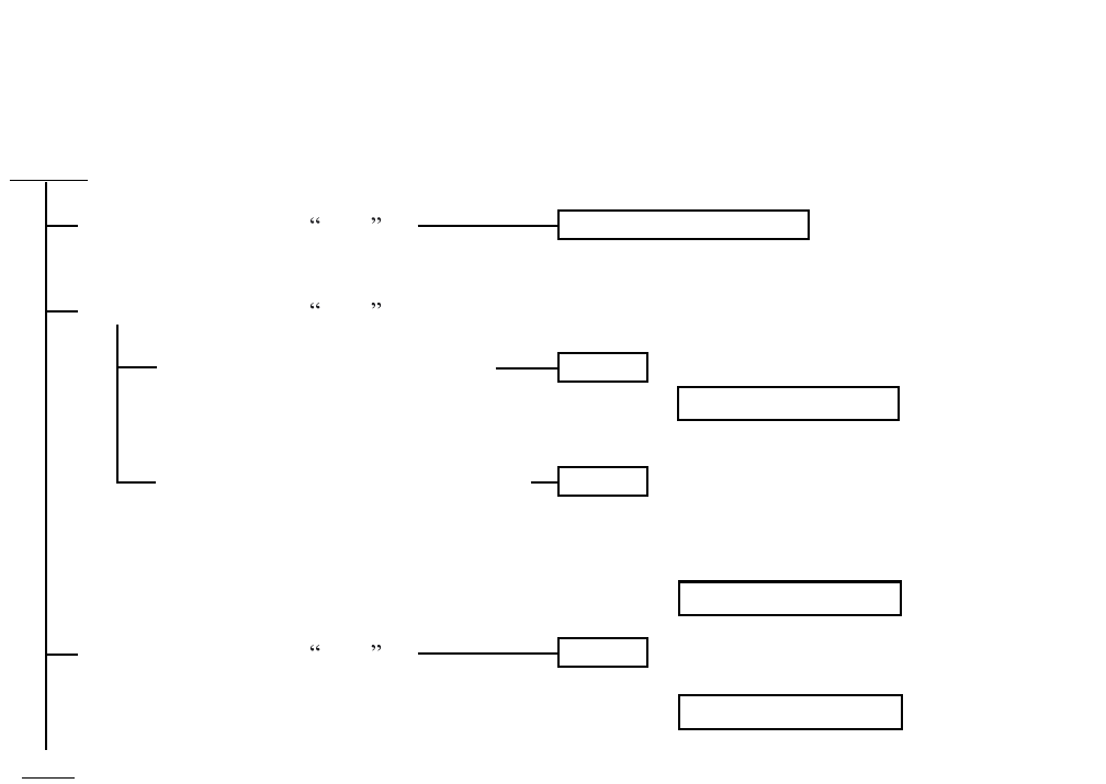
ND-71762 (E) CHAPTER 8
Page 95
Issue 2
MAINTENANCE PROCEDURE
(5) Diagnostic Work
START
END
When system message 13-C is
displayed once or twice
When system message 13-C is displayed sporadically
Even if the CCH/CCT is stopped,
it does not affect the system.
If the CCH/CCT is stopped, it affects
the system.
When system message 13-C is
displayed cyclically
FAULT SUPERVISION
FAULT : CCH/CCT circuit card is faulty.
FAULT : Place the CCH/CCT into make-busy
state during daytime, and replace
the CCH/CCT card with spare.
FAULT : CCH/CCT circuit card is faulty.
Paragraphs 3.3 or 3.4
Paragraphs 3.3 or 3.4
Paragraphs 3.3 or 3.4

CHAPTER 8 ND-71762 (E)
Page 96
Issue 2
MAINTENANCE PROCEDURE
“13-D”: CCH Lock Up Failure (Permanent)
(1) Meaning
The system message “13-D” indicates that a PM (Port Microprocessor) of CCH/CCT card did not send CPU
card an answer and this has occurred more than 15 times within an hour. When this fault has occurred, the
specific PM is placed into make-busy state and restarted.
Note: The CPU transmits the Routine (cyclic) diagnostic command to all the PM’s at a predetermined cycle. Each
PM upon receiving the Routine (cyclic) diagnostic command from the CPU, returns an answer to the CPU
within a predetermined timing. The CPU checks the normality of the PM upon receiving an answer.
(2) Related System Message
When the PM Lock Up Failure occurs less than 16 times within an hour, the Phase 1 restart or Phase 3 restart
is executed at the specific PM and the system message “13-E” is output.
(3) Example of Printout
(4) Message Detail Data
(a) Accommodated location of the CCH detected fault.
(Refer to paragraph 2.2.1)
SYSTEM MESSAGE 13-D [SUP] CCH LOCK UP FAILURE (PERMANENT)
NEC TOKYO MAY 14 10:30
LP00-0-ACT
1:
XX
00 0000 0000 0000 2: 0000 0000 0000 0000 3: 0000 0000 0000 0000
4: 0000 0000 0000 0000 5: 0000 0000 0000 0000 6: 0000 0000 0000 0000
7: 0000 0000 0000 0000 8: 0000 0000 0000 0000 9: 0000 0000 0000 0000
(a)
MG U G
MG:
U:
G:
Module Group
Unit
Group
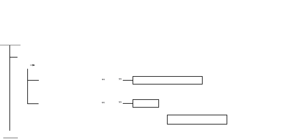
ND-71762 (E) CHAPTER 8
Page 97
Issue 2
MAINTENANCE PROCEDURE
(5) Diagnostic Work
START
END
When one CCH/CCT circuit card is faulty, Trun ON the MBR key on the card, and then set the MB key
ON OFF.
When system message 13-D FAULT SUPERVISION
is not displayed.
When system message 13-D FAULT : CCH/CCT circuit card is faulty.
is displayed.
Paragraphs 3.3 or 3.4

CHAPTER 8 ND-71762 (E)
Page 98
Issue 2
MAINTENANCE PROCEDURE
“13-E”: CCH Lock Up Failure (Temporary)
(1) Meaning
The system message “13-E” indicates that a PM (Port Microprocessor) of CCH/CCT card did not send CPU
an answer and this has occurred less than 16 times within an hour. When the number of fault occurrence time
is less than 8, the Phase 1 restart is executed. If the number of the fault occurrence time is 8 to 16, the Phase 3
restart is executed.
Note: The CPU transmits the Routine (cyclic) diagnostic command to all the PM’s at a predetermined cycle. Each
PM upon receiving the Routine (cyclic) diagnostic command from the CPU, returns an answer to the CPU
within a predetermined timing. The CPU checks the normality of the PM upon receiving an answer.
(2) Related System Message
When the PM Lock Up Failure occurs more than 15 times, the specific PM of CCH/CCT card is placed into
make-busy state and the system message “13-D” is output.
(3) Example of Printout
(4) Message Detail Data
(a) Accommodated location of the CCH detected the fault.
(Refer to paragraph 2.2.1)
SYSTEM MESSAGE 13-E [SUP] CCH LOCK UP FAILURE (TEMPORARY)
NEC TOKYO MAY 14 10:30
LP00-0-ACT
1:
XX
00 0000 0000 0000 2: 0000 0000 0000 0000 3: 0000 0000 0000 0000
4: 0000 0000 0000 0000 5: 0000 0000 0000 0000 6: 0000 0000 0000 0000
7: 0000 0000 0000 0000 8: 0000 0000 0000 0000 9: 0000 0000 0000 0000
(a)
MG U G
MG:
U:
G:
Module Group
Unit
Group
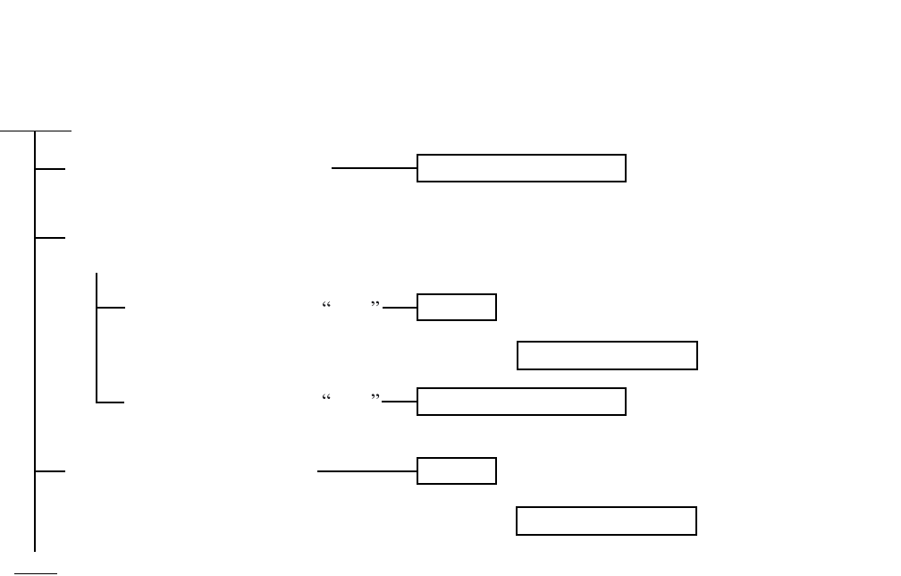
ND-71762 (E) CHAPTER 8
Page 99
Issue 2
MAINTENANCE PROCEDURE
(5) Diagnostic Work
START
END
FAULT SUPERVISION
FAULT : CCH/CCT circuit card is faulty.
FAULT SUPERVISION
FAULT : CCH/CCT circuit card is faulty.
When lock up fault occurs only
once or twice.
If the lock up fault occurs sporadically; flip the MBR switch of the CCH circuit card to
UP → DOWN.
When system message 13-E
is displayed
When system message 13-E
is not displayed
When the lock up fault occurs
cyclically
Paragraphs 3.3 or 3.4
Paragraphs 3.3 or 3.4

CHAPTER 8 ND-71762 (E)
Page 100
Issue 2
MAINTENANCE PROCEDURE
“13-F”: CCH B-Level Infinite Loop Failure (Permanent)
(1) Meaning
The system message “13-F” indicates that B-level infinite loop (Note) of the PM (Port Microprocessor) within
the CCH/CCT circuit card has occurred more than 15 times within an hour. When this fault has occurred, the
specific PM is placed into make-busy state and restarted. (The fault counter is reset to “0” at every hour.)
Note: This is such a state in which the C-Level Monitor Program (the program which detects off-hook/on-hook
related to lines/trunks) repeats a specific routine. The number of repeated times is counted by the error
counter corresponding to the CPU.
(2) Related System Message
When the B-level infinite loop failure occurs less than 16 times, the Phase 1 restart or Phase 3 restart is exe-
cuted at the specific PM and the system message “13-G” is output.
(3) Example of Printout
(4) Message Detail Data
(a) Accommodated location of the CCH detected the fault.
(Refer to paragraph 2.2.1)
SYSTEM MESSAGE 13-F [SUP] CCH B-LEVEL INFINITE LOOP FAILURE (PERMANENT)
NEC TOKYO MAY 14 10:30
LP00-0-ACT
1:
XX
00 0000 0000 0000 2: 0000 0000 0000 0000 3: 0000 0000 0000 0000
4: 0000 0000 0000 0000 5: 0000 0000 0000 0000 6: 0000 0000 0000 0000
7: 0000 0000 0000 0000 8: 0000 0000 0000 0000 9: 0000 0000 0000 0000
(a)
MG U G
MG:
U:
G:
Module Group
Unit
Group
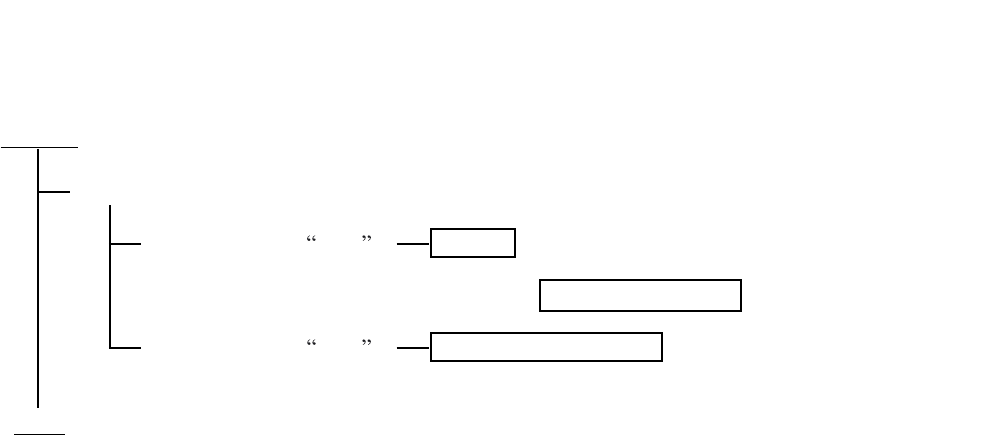
ND-71762 (E) CHAPTER 8
Page 101
Issue 2
MAINTENANCE PROCEDURE
(5) Diagnostic Work
START
END
Turn ON the MBR key on the CCH/CCT card, and then set the MB key ON→OFF.
System Message 13-F is FAULT : CCH/CCT circuit card is faulty.
displayed again.
System Message 13-F is FAULT SUPERVISION
not displayed.
Paragraphs 3.3 or 3.4

CHAPTER 8 ND-71762 (E)
Page 102
Issue 2
MAINTENANCE PROCEDURE
“13-G”: CCH B-Level Infinite Loop Failure (Temporary)
(1) Meaning
The system message “13-G” indicates that B-level Infinite loop for PM (Port Microprocessor) within a CCH/
CCT circuit card has occurred less than 16 times within an hour.
(2) Related System Message
When the B-level infinite loop failure occurs more than 15 times, the specific PM is placed into make-busy
state and the system message “13-F” is output.
(3) Example of Printout
(4) Message Detail Data
(a) Accommodated location of the CCH detected the fault.
(Refer to paragraph 2.2.1)
SYSTEM MESSAGE 13-G [SUP] CCH B-LEVEL INFINITE LOOP FAILURE (TEMPORARY)
NEC TOKYO MAY 14 10:30
LP00-0-ACT
1:
XX
00 0000 0000 0000 2: 0000 0000 0000 0000 3: 0000 0000 0000 0000
4: 0000 0000 0000 0000 5: 0000 0000 0000 0000 6: 0000 0000 0000 0000
7: 0000 0000 0000 0000 8: 0000 0000 0000 0000 9: 0000 0000 0000 0000
(a)
MG U G
MG:
U:
G:
Module Group
Unit
Group
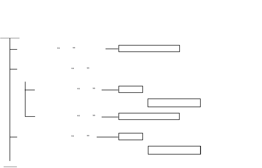
ND-71762 (E) CHAPTER 8
Page 103
Issue 2
MAINTENANCE PROCEDURE
(5) Diagnostic Work
System message 13-G is displayed
once or twice.
When system message 13-G is displayed sporadically, flip the MBR switch of the CCH circuit card
UP → DOWN.
System message 13-G is
displayed again
System message 13-G is
not displayed
When system message 13-G is
displayed cyclically.
START
END
FAULT SUPERVISION
FAULT : CCH/CCT circuit card is faulty.
FAULT SUPERVISION
FAULT : CCH/CCT circuit card is faulty.
Paragraphs 3.3 or 3.4
Paragraphs 3.3 or 3.4
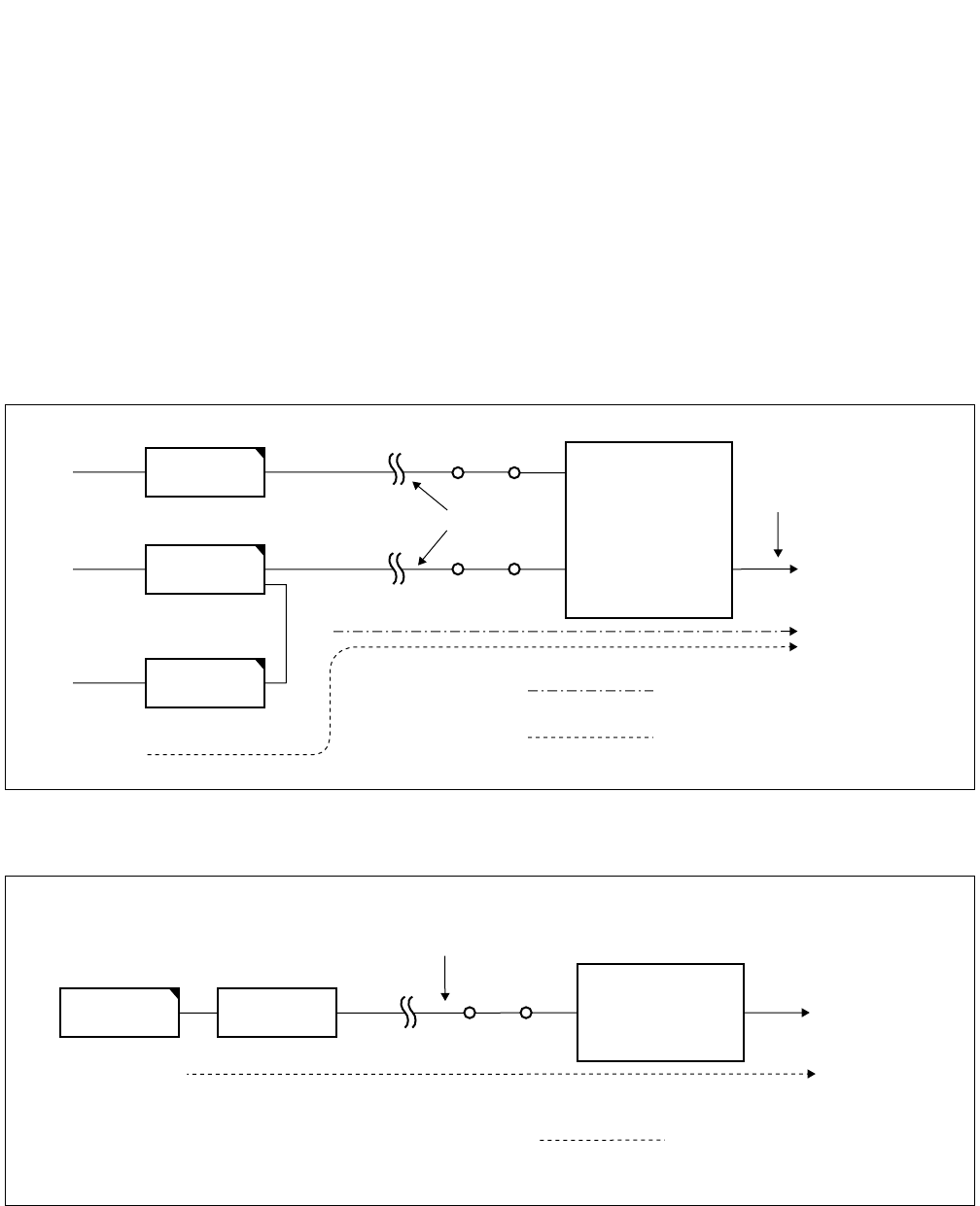
CHAPTER 8 ND-71762 (E)
Page 104
Issue 2
MAINTENANCE PROCEDURE
“13-H”: CCS Link Failure (Permanent)
(1) Meaning
The system message “13-H” indicates that a failure has occurred many times to a common channel signaling
link and the link has been placed into make-busy state.
(2) Related System Message
When the failure is a temporary one, the system message “13-I” is output. If the failure of CCIS link restores
to normal, “13-J” is output.
Figure 8-3 Digital CCIS Line
Figure 8-4 Analog CCIS Line
Digital Line
Line for speech path and signal
to Distant office
Speech Signal
Control Signal
DTI
CCH
MDF
MDF
CCT
Digital Carrier
Equipment
Signal Line
CCH
Analog Carrier
Equipment
MDF
Control Signal
MODEM
to Distant office

ND-71762 (E) CHAPTER 8
Page 105
Issue 2
MAINTENANCE PROCEDURE
(3) Example of Printout
(4) Message Detail Data
(a) Accommodated location of the CCH detected the failure.
(Refer to paragraph 2.2.1)
(b),(c) Data for Analysis by NEC Engineers.
SYSTEM MESSAGE 13-H [SUP] CCS LINK FAILURE (PERMANENT)
NEC TOKYO MAY 14 10:30
LP00-0-ACT
1:
XX XX
XX
00 0000 0000 2: 0000 0000 0000 0000 3: 0000 0000 0000 0000
4: 0000 0000 0000 0000 5: 0000 0000 0000 0000 6: 0000 0000 0000 0000
7: 0000 0000 0000 0000 8: 0000 0000 0000 0000 9: 0000 0000 0000 0000
(a) (b) (c)
MG U G
MG:
U:
G:
Module Group
Unit
Group
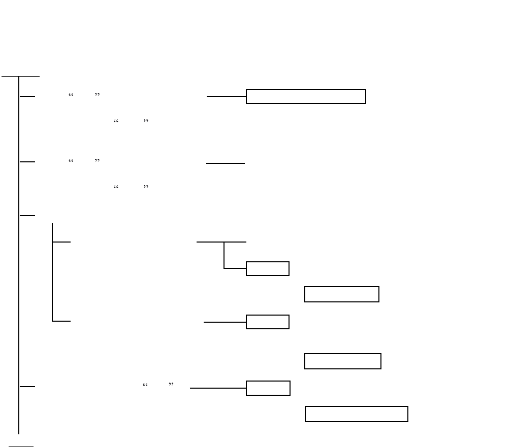
CHAPTER 8 ND-71762 (E)
Page 106
Issue 2
MAINTENANCE PROCEDURE
(5) Diagnostic Work
START
END
FAULT SUPERVISION :
A CCS link failure occurred, but it has restored to
normal.
Ask the distant office if it has not been placed
into make-busy state for maintenance reason,
etc.
Check the carrier equipment.
FAULT : DTI, flat cable is faulty.
FAULT : MODEM and MODEM cable are
faulty.
FAULT : CCH/CCT circuit card is faulty.
When 13-J (Restoration from CCS
Link Failure) is displayed after
system message 13-H
When 13-J (Restoration from CCS
Link failure) is not displayed after
system message 13-H
When the distant office is not under make-busy state.
When DTI is in use as the
control link to the distant
office.
When MODEM is in use as
the control link to the distant
office.
When system message 13-I is
displayed.
Paragraphs 3.3 or 3.4
Paragraphs 3.3
Paragraphs 3.4
ND-71762 (E) CHAPTER 8
Page 107
Issue 2
MAINTENANCE PROCEDURE
“13-I”: CCS Link Failure (Temporary)
(1) Meaning
The system message “13-I” indicates that a failure has occurred to a common channel signaling link tempo-
rarily.
(2) Related System Message
If the fault lasts longer than a predetermined duration, the system message “13-H” is indicated. If the fault of
CCIS link restores to normal, “13-J” is indicated.
(3) Example of Printout
(4) Example of Printout
(a) Accommodated location of the CCH detected the fault.
(Refer to paragraph 2.2.1)
(b),(c) Data for Analysis by NEC Engineers.
SYSTEM MESSAGE 13-I [NON] CCS LINK FAILURE (TEMPORARY)
NEC TOKYO MAY 14 10:30
LP00-0-ACT
1:
XX
XX
XX
00 0000 0000 2: 0000 0000 0000 0000 3: 0000 0000 0000 0000
(a) (b) (c)
MG U G
MG:
U:
G:
Module Group
Unit
Group
CHAPTER 8 ND-71762 (E)
Page 108
Issue 2
MAINTENANCE PROCEDURE
(5) Diagnostic Work
START
END
When system message 13-I is
placed once or twice.
When system message 13-I is displayed sporadically.
When system message 13-J
is displayed after system
message 13-I .
When system message 13-J
is not displayed after system
message 13-I .
When system message 13-I is
displayed cyclically.
FAULT SUPERVISION
FAULT SUPERVISION :
A CCS link failure occurred, but it has restored
to normal.
FAULT : CCH/CCT circuit card is faulty.
FAULT : CCH/CCT circuit card is faulty.
Paragraphs 3.3 or 3.4
Paragraphs 3.3 or 3.4

ND-71762 (E) CHAPTER 8
Page 109
Issue 2
MAINTENANCE PROCEDURE
“13-J”: Restoration from CCS Link Failure
(1) Meaning
The system message “13-J” indicates that the faults pertaining to CCIS Link restores to normal.
(2) Related System Message
This system message is displayed when a fault indicated by System Message “13-I” or “13-H” has been re-
paired.
(3) Example of Printout
(4) Example of Printout
(a) Accommodated location of the CCH detected the fault.
(Refer to paragraph 2.2.1)
(b) Data for Analysis by NEC Engineers.
SYSTEM MESSAGE 13-J [NON] RESTORATION FROM CCS LINK FAILURE
NEC TOKYO MAY 14 10:30
LP00-0-ACT
1:
XX
XX
0000 0000 0000 2: 0000 0000 0000 0000 3: 0000 0000 0000 0000
4: 0000 0000 0000 0000 5: 0000 0000 0000 0000 6: 0000 0000 0000 0000
7: 0000 0000 0000 0000 8: 0000 0000 0000 0000 9: 0000 0000 0000 0000
(a) (b)
MG U G
MG:
U:
G:
Module Group
Unit
Group

CHAPTER 8 ND-71762 (E)
Page 110
Issue 2
MAINTENANCE PROCEDURE
“13-K”: CCH Reset Interrupt Failure
(1) Meaning
The system message “13-K” indicates that a fault occurred to the PM (Port Microprocessor) within the CCH/
CCT circuit card and the restart processing is executed.
Note: This message is also displayed when the CCH/CCT circuit card has been reset.
(2) Related System Message
None
(3) Example of Printout
(4) Message Detail Data
(a) Accommodated location of the CCH detected the fault.
(Refer to paragraph 2.2.1)
SYSTEM MESSAGE 13-K [SUP] CCH RESET INTERRUPT FAILURE
NEC TOKYO MAY 14 10:30
LP00-0-ACT
1:
XX
00 0000 0000 0000 2: 0000 0000 0000 0000 3: 0000 0000 0000 0000
4: 0000 0000 0000 0000 5: 0000 0000 0000 0000 6: 0000 0000 0000 0000
7: 0000 0000 0000 0000 8: 0000 0000 0000 0000 9: 0000 0000 0000 0000
(a)
MG U G
MG:
U:
G:
Module Group
Unit
Group

ND-71762 (E) CHAPTER 8
Page 111
Issue 2
MAINTENANCE PROCEDURE
(5) Diagnostic Work
START
END
Turn ON the MBR key on the CCH/CCT circuit card, and then set the MB key ON→OFF.
System Message 13-K is FAULT SUPERVISION
displayed again
System Message 13-K is FAULT : CCH/CCT card is faulty.
not displayed
Paragraphs 3.3 or 3.4
CHAPTER 8 ND-71762 (E)
Page 112
Issue 2
MAINTENANCE PROCEDURE
7-A”: CCH MBR Key Turn ON
(1) Meaning
The system message “17-A” indicates that a MBR (Make Busy Request) switch on the CCH/CCT card has
been set Up.
(2) Related System Message
If the position of MBR switch of a CCH/CCT card has changed from Up to Down, the system “17-B” is output.
(3) Example of Printout
(4) Message Detail Data
(a) Accommodated location of the CCH circuit in make busy request.
(Refer to paragraph 2.2.1)
(b) Data for Analysis by NEC Engineers.
SYSTEM MESSAGE 17-A [NON] CCH MBR KEY TURN ON
NEC TOKYO MAY 14 10:30
LP00-0-ACT
1:
XX
XX
0000 0000 0000 2: 0000 0000 0000 0000 3: 0000 0000 0000 0000
4: 0000 0000 0000 0000 5: 0000 0000 0000 0000 6: 0000 0000 0000 0000
7: 0000 0000 0000 0000 8: 0000 0000 0000 0000 9: 0000 0000 0000 0000
(a) (b)
MG U G
MG:
U:
G:
Module Group
Unit
Group

ND-71762 (E) CHAPTER 8
Page 113
Issue 2
MAINTENANCE PROCEDURE
“17-B”: CCH MBR Key Turn OFF
(1) Meaning
The system message “17-B” indicates that a MBR switch on the CCH/CCT card has been set Down.
(2) Related System Message
If the position of MBR switch of a CCH/CCT card has changed from Down to Up, the system message “17-
A” is output.
(3) Example of Printout
(4) Message Detail Data
(a) Accommodated location of the CCH circuit detected make busy request cancel.
(Refer to paragraph 2.2.1)
(b) Data for Analysis by NEC Engineers.
SYSTEM MESSAGE 17-B [NON] CCH MBR KEY TURN OFF
NEC TOKYO MAY 14 10:30
LP00-0-ACT
1:
XX
XX
0000 0000 0000 2: 0000 0000 0000 0000 3: 0000 0000 0000 0000
4: 0000 0000 0000 0000 5: 0000 0000 0000 0000 6: 0000 0000 0000 0000
7: 0000 0000 0000 0000 8: 0000 0000 0000 0000 9: 0000 0000 0000 0000
(a) (b)
MG U G
MG:
U:
G:
Module Group
Unit
Group
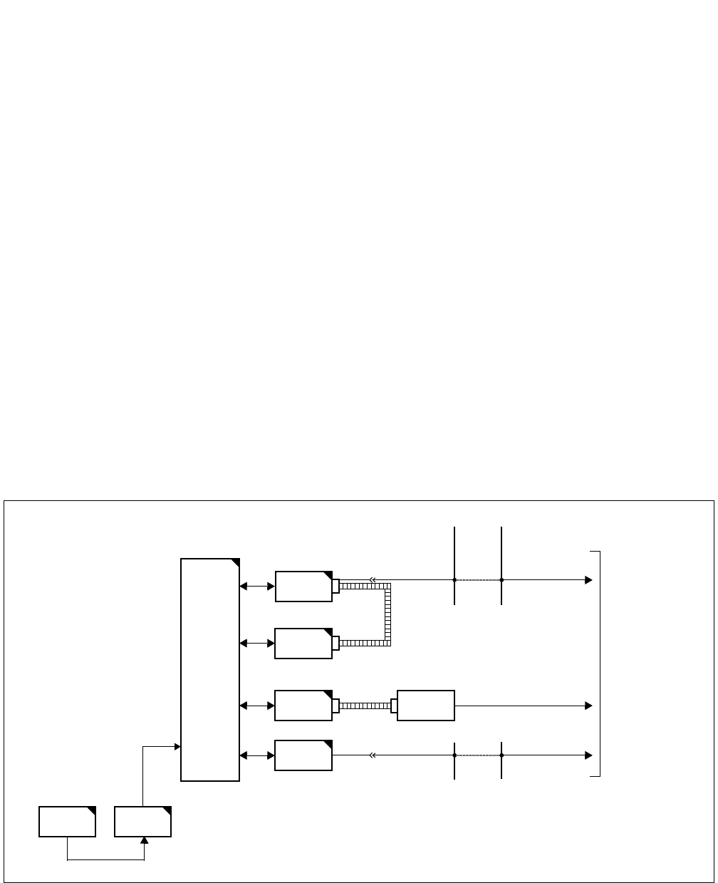
CHAPTER 8 ND-71762 (E)
Page 114
Issue 2
MAINTENANCE PROCEDURE
3. CCIS (Common Channel Interoffice Signaling) Line Fault
This paragraph explains the fault repair procedure when any of the faults shown in Table 8-1 occur to a specific
CCIS line.
3.1 Check Point
When repairing a CCIS Line fault, consider the following:
(1) Check alarm lamps on the CCH or CCT circuit card
(2) By referring to Figure 8-5, check the cable connection.
3.2 CCIS Line Control
The CCH within the CCH/CCT circuit card controls the signal link of the interoffice common channel signaling sys-
tem and transmits/receives call processing information.
The signal link controls to send/receive the call processing information.
The call processing information is converted into No. 7 signal format for channel 1 (any channel) of the DTI before
being transmitted to a distant office.
Figure 8-5 Controlling the CCIS Line
MUX
CPU TSW
DTI
CCH
FRONT
CABLE
LT Cable
MDF
CCH MODEM
To CCIS Line
MODEM CABLE
CCT LT Cable MDF
ND-71762 (E) CHAPTER 8
Page 115
Issue 2
MAINTENANCE PROCEDURE
3.3 Fault Repair Procedure for Digital CCIS Line
START
END
On the DTI card, set the MBR switch UP . On the CCH card,
set the SW01-0, 1 UP .
On the DTI/CCH card, set the MB switches UP .
Check whether the connector is correctly connected or not for
both cards. If the connection is found an improper connection, plug and
unplug the connector for a few times.
On the DTI and CCH cards, set the MB and MBR switches
DOWN .
Check whether the fault is still indicated or not.
On the DTI card, set the MBR switch UP . On the CCH card,
set the SW01-0, 1 UP .
On the DTI and CCH card, set the MB switches UP .
Test the continuity of the flat cable. If found abnormal,
replace the flat cable with spare.
On the DTI and CCH cards, set the MB and MBR switches
DOWN .
Check whether the fault is still indicated or not.
On the DTI card, set the MBR switch UP and then MB switch
UP .
Extract the card from the mounting slot.
On a new DTI card, make switch setting referring to the
extracted card.
On the new DTI card, set the MBR switch UP .
On the new DTI card, set the MB switch UP and insert the
card into the mounting slot.
On the new DTI card, set the MBR and MB switches DOWN .
Check whether the fault is still indicated or not.
On the CCH/CCT card, set the MBR switch UP.
Note : MBR switch s name varies depending on the card.
On the CCH/CCT card, set the MB switch UP and extract the
card from its mounting slot.
Make switch setting on the new CCH/CCT card, referring to
the card extracted.
On the new CCH/CCT card, set the MBR and MB switches
UP and insert the card into its mounting slot.
On the new CCH/CCT card, set the MB switch DOWN .
On the new CCH/CCT card, set the MBR switch DOWN .
Check whether the fault is still indicated.
Check the connectors and flat cables between DTI and CCH.
Check the connector
Check the flat cable
Check by replacing the DTI card
with spare
Check by replacing the CCH/CCT
card with spare
CHAPTER 8 ND-71762 (E)
Page 116
Issue 2
MAINTENANCE PROCEDURE
3.4 Fault Repair Procedure for Analog CCIS Line
Check the MODEM and the MODEM Cable
Check the MODEM
Cable connector
Check the MODEM
Cable
Check the MODEM
START
A
On the CCH card, set the MBR switch (SW01-1, 2) UP .
Check whether the connector is correctly connected or
not. If the connection is found improperly, plug and unplug
the connector for a few times.
On the CCH card, set the MBR switch DOWN .
Check whether the fault is still indicated or not.
On the CCH card, set the MBR switch UP .
Test the continuity of the MODEM cable. If found
abnormal, replace the cable with a spare.
On the CCH card, set the MBR switch DOWN .
Check whether the fault is still indicated or not.
Check whether the alarm lamp is illuminating on the
MODEM.
On the CCH card, set the MBR switch UP .
Test the MODEM.
On the CCH card, set the MBR switch DOWN .
Check whether the fault is still indicated or not.

ND-71762 (E) CHAPTER 8
Page 117
Issue 2
MAINTENANCE PROCEDURE
On the CCH card, set the MBR switch (SW01-1, 2) UP .
On the CCH card, set the MB switch UP and extract the card
from its mounting slot.
Make switch setting on a new CCH card, referring to the
replaced card.
On the new CCH card, set the MBR and MB switches UP
and insert the card into its mounting slot.
On the new CCH card, set the MB switch DOWN .
On the new CCH card, set the MBR switch DOWN .
Check whether the fault is still indicated.
Check by replacing the CCH
card with spare
A
END

CHAPTER 8 ND-71762 (E)
Page 118
Issue 2
MAINTENANCE PROCEDURE
4. CCIS LINE OPERATING MODE CONTROL
This Section describes the Make Busy/Make Busy Cancel procedure and the Reinitialization procedure for CCH cir-
cuit.
Make Busy/Make Busy Cancel
of CCH
Reinitialization of CCH
Circuit Card
Command CCSE : Make Busy/Make Busy Cancel for a
CCH circuit (not including speech path
cannels).
MBR switch : Make Busy/Make Busy Cancel for a CCH
circuit (not including speech path cannels).
MB switch : Make Busy/Make Busy Cancel for a CCH/
CCT circuit card.
Note : The MBR switch s name varies depending on the card.
MBR Switch operation on CCH circuit card.
Set the MB switch UP and confirm that the OPE lamp goes out.
About 3 seconds later, set the MB switch DOWN and confirm
that the OPE lamp illuminates.
CCIS Line Operating Mode Control

ND-71762 (E) CHAPTER 8
Page 119
Issue 2
MAINTENANCE PROCEDURE
5. INSERTION/EXTRACTION OF CIRCUIT CARDS
This paragraph explains the procedure for inserting CCH, DTI, CCT and PLO/OSC circuit cards into their mounting
slots and extracting them while the system is in On-Line mode.
5.1 CCH Circuit Card
(1) Procedure for Extraction:
(2) Procedure for Insertion:
START
END
Set the MBR switch (SW01-0, 1) of the CCH card UP .
Set the MB switch of the CCH card UP .
The OPE lamp (green) goes out and the N-OPE lamp (red) illuminates on the CCH card.
When the CCH card is connected with the DTI card via the front cable, remove the front cable from the
CCH card.
Extract the CCH card from its mounting slot.
START
END
Set the MBR switch (SW01-0, 1) and MB switch of the CCH card UP .
Insert the CCH card into its mounting slot.
Set the MB switch of the CCH card DOWN .
Set the MBR switch of the CCH card DOWN .
The OPE lamp of the CCH card illuminates.
When the CCH card is connected with the DTI card, connect the front cable referring to CHAPTER 4
“INSTALLATION PROCEDURE”.

CHAPTER 8 ND-71762 (E)
Page 120
Issue 2
MAINTENANCE PROCEDURE
5.2 DTI Circuit Card
(1) Procedure for Extraction:
(2) Procedure for Insertion:
START
END
Set the MBR switch (SW01-0, 1) UP on the CCH card connected via the front cable with the DTI card.
Set the MB switch UP on the CCH card.
The OPE lamp (green) goes out and N-OPE lamp (red) illuminates on the CCH card.
Set the MB switch UP on the DTI card.
The OPE lamp (green) goes out and the N-OPE lamp (red) illuminates on the DTI card.
Remove the front cable of the DTI card.
Extract the DTI card from its mounting slot.
START
END
Set the MB switch of the DTI card UP .
Insert the DTI card into its mounting slot.
Connect the front cable between DTI and CCH card.
Set the MB switch of the DTI circuit card DOWN .
The OPE lamp of the DTI card illuminates.
Set the MB and MBR switch on the CCH card DOWN .
Confirm that the OPE lamp (green) illuminates on the CCH card connected with the DTI card via the
front cable.
ND-71762 (E) CHAPTER 8
Page 121
Issue 2
MAINTENANCE PROCEDURE
5.3 CCT Circuit Card
(1) Procedure for Extraction:
(2) Procedure for Insertion:
START
END
Set the MBR switch of the CCT card UP .
Note :
As for the 24 CCT card, set the SW01/13B-1, 2 UP .
Set the MB switch of the CCT card UP .
The OPE lamp (green) goes out and the N-OPE lamp (red) illuminates on the CCT card.
Extract the CCT card from its mounting slot.
START
END
Set the MBR switch and MB switch on the CCT card UP .
Note :
As for the 24 CCT card, set the SW01/13B-1, 2 UP as MBR switch set.
Insert the CCT card into its mounting slot.
Set the MBR switch and MB switch on the CCT card DOWN .
The OPE lamp on the CCT card illuminates.

CHAPTER 8 ND-71762 (E)
Page 122
Issue 2
MAINTENANCE PROCEDURE
5.4 PLO/OSC Circuit Card
(1) Procedure for Extraction:
(2) Procedure for Insertion:
START
END
Set the MB switch of the PLO/OSC card UP.
The OPE/CLKOUT lamp (green) goes out.
Extract the PLO/OSC card from its mounting slot.
START
END
Set the MB switch of the PLO/OSC card UP .
Insert the PLO/OSC card into its mounting slot.
Set the MB switch of the PLO/OSC card DOWN .
The OPE/CLKOUT lamp (green) illuminates.

ISSUE 1 ISSUE 2 ISSUE 3 ISSUE 4
DATE MAY, 2002 DATE AUGUST, 2002 DATE DATE
ISSUE 5 ISSUE 6 ISSUE 7 ISSUE 8
DATE DATE DATE DATE
NEAX2400 IPX Internet Protocol eXchange
No.7 CCIS System Manual Revision Sheets 1/2
ND-71762(E)
PAGE No. ISSUE No.
12345678
PL-1 1 2
PL-2 1 2
PL-3 1 2
PL-4 1 2
PL-5 1 2
PL-6 1 2
PL-7 1 2
PL-8 1 2
i 1 2
ii 1 2
iii 1 2
Blank 1 2
1 1 2
2 1 2
312
41
2
5 1 2
6 1 2
712
81
2
9 1 2
10 1 2
11 1 2
12 1 2
13 1 2
14 1 2
15 1 2
16 1 2
17 1 2
18 1 2
19 1 2
20 1 2
21 1 2
22 1 2
23 1 2
24 1 2
25 1 2
26 1 2
27 1 2
28 1 2
29 1 2
30 1 2
31 1 2
32 1 2
33 1 2
34 1 2
35 1 2
36 1 2
37 1 2
38 1 2
39 1 2
40 1 2
41 1 2
42 1 2
43 1 2
44 1 2
45 1 2
46 1 2
47 1 2
48 1 2
49 1 2
50 1 2
51 1 2
52 1 2
53 1 2
54 1 2
55 1 2
56 1 2
57 1 2
58 1 2
59 1 2
60 1 2
61 1 2
62 1 2
63 1 2
64 1 2
PAGE No. ISSUE No.
12345678

ISSUE 1 ISSUE 2 ISSUE 3 ISSUE 4
DATE MAY, 2002 DATE AUGUST, 2002 DATE DATE
ISSUE 5 ISSUE 6 ISSUE 7 ISSUE 8
DATE DATE DATE DATE
NEAX2400 IPX Internet Protocol eXchange
No.7 CCIS System Manual Revision Sheets 2/2
ND-71762(E)
65 1 2
66 1 2
67 1 2
68 1 2
69 1 2
70 1 2
71 1 2
72 1 2
73 1 2
74 1 2
75 1 2
76 1 2
77 1 2
78 1 2
79 1 2
80 1 2
81 1 2
82 1 2
83 1 2
84 1 2
85 1 2
86 1 2
87 1 2
88 1 2
89 1 2
90 1 2
91 1 2
92 1 2
93 1 2
94 1 2
95 1 2
96 1 2
97 1 2
98 1 2
99 1 2
100 1 2
101 1 2
102 1 2
PAGE No. ISSUE No.
12345678
103 1 2
104 1 2
105 1 2
106 1 2
107 1 2
108 1 2
109 1 2
110 1 2
111 1 2
112 1 2
113 1 2
114 1 2
115 1 2
116 1 2
117 1 2
118 1 2
119 1 2
120 1 2
121 2
122 2
PAGE No. ISSUE No.
12345678
