Nedap N V FLRRFMD Anti-Pilferage device User Manual Manual FLR line

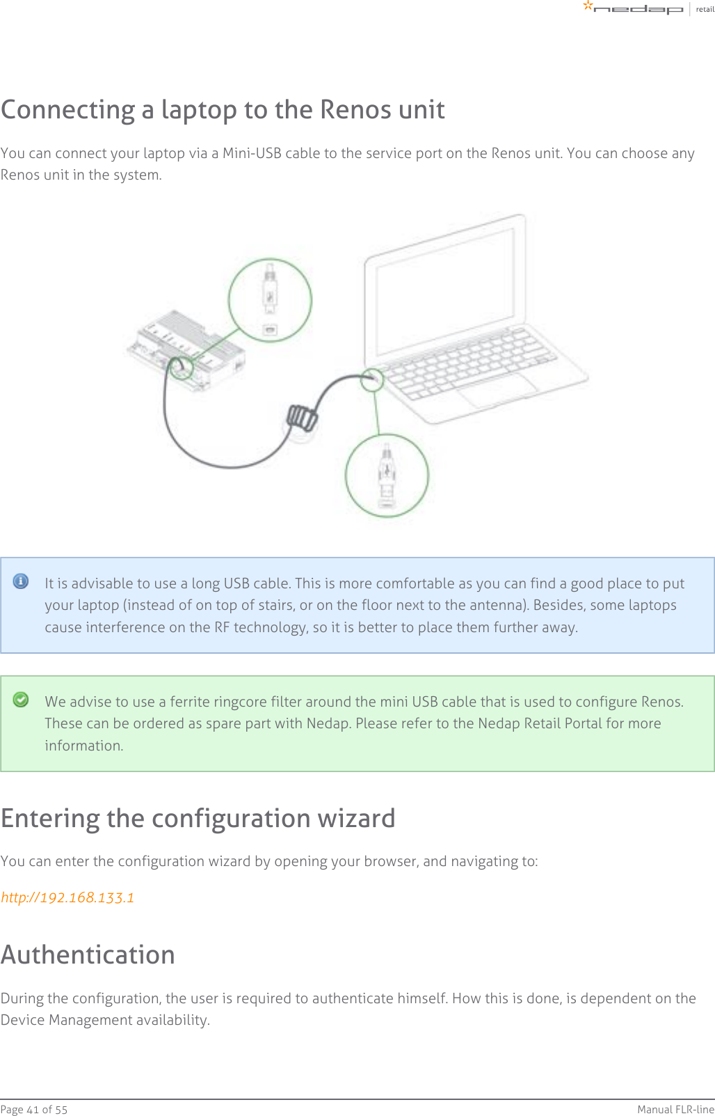
N. V. Nederlandsche Apparatenfabriek NEDAP Anti-Pilferage device Manual FLR line

14_Manual FLR-line-v177-20140821_1122 CGDFLRRFMD

PRELIMINARYi30i45!D Gate!D Hybrid GateFirmware version 14.35 and newerManual FLR-line
Page   of 2 55 Manual FLR-lineContents1 Introduction  _________________________________________________________________________________ 4RFID Regions  ______________________________________________________________________________ 5CE WEEE  __________________________________________________________________________________ 5Battery disposal  ___________________________________________________________________________ 62 Product overview  ____________________________________________________________________________ 7Box contents  ______________________________________________________________________________ 7Components  ______________________________________________________________________________ 8Dimensions  ______________________________________________________________________________ 10Connections  _____________________________________________________________________________ 13Add-ons  _________________________________________________________________________________ 143 Preparing the installation  ____________________________________________________________________ 16Defining the system  _______________________________________________________________________ 16Field distribution  _________________________________________________________________________ 17Detection distance, aisle width and label-free zone ____________________________________________ 19RFID installation requirements ______________________________________________________________ 22Power Inserter ____________________________________________________________________________ 23Cabling  __________________________________________________________________________________ 24Device Management  ______________________________________________________________________ 264 Executing the installation  ____________________________________________________________________ 28Conduit or slit  ____________________________________________________________________________ 28Physical installation  _______________________________________________________________________ 29Orientation of products  ____________________________________________________________________ 31Installing cabling and filters  ________________________________________________________________ 35Status LEDs  ______________________________________________________________________________ 375 Configuring the installation ___________________________________________________________________ 40Driver installation _________________________________________________________________________ 40Recent browser ___________________________________________________________________________ 40Connecting a laptop to the Renos unit  _______________________________________________________ 41Entering the configuration wizard  ___________________________________________________________ 41Authentication  ___________________________________________________________________________ 41Getting help in the wizard __________________________________________________________________ 42Firmware version and System ID  ____________________________________________________________ 42Factory reset  _____________________________________________________________________________ 42Firmware change  _________________________________________________________________________ 436 Integrating the installation with other systems  __________________________________________________ 45Software integration with API's  _____________________________________________________________ 45Physical integration using an IO Box  _________________________________________________________ 45URL trigger _______________________________________________________________________________ 46
Page   of 3 55 Manual FLR-line7 Servicing the installation  _____________________________________________________________________ 47Nedap Device Management  ________________________________________________________________ 47SNMP  ___________________________________________________________________________________ 478 Troubleshooting  ____________________________________________________________________________ 48Physical installation  _______________________________________________________________________ 48Configuration  ____________________________________________________________________________ 49RF technology issues  ______________________________________________________________________ 499 Regulatory information  ______________________________________________________________________ 52FCC and IC Compliance statement ___________________________________________________________ 52FCC and IC Radiation Exposure Statement  ____________________________________________________ 52FCC Information to the user  ________________________________________________________________ 5310 About Nedap  _______________________________________________________________________________ 54About  ___________________________________________________________________________________ 54Contact __________________________________________________________________________________ 54
Page   of 4 55 Manual FLR-line1 IntroductionThe Nedap FLR-line products are gates that can be equipped with Ultra High Frequency (UHF) RFID and/or 8.2MHz RF detection technology. In addition to those technologies, it is possible to add infrared beam sensors fordirection detection or customer counting. The gates are specifically designed for in-store retail applications,such as Electronic Article Surveillance (EAS), stock room to sales floor transition and goods receiving.Knowledge Base articlesThis manual provides an overview of the products, the installation and configuration. To obtain moredetails on various topics or background information, several Knowledge Base articles are available,and are referred to in this manual. You can find the Knowledge Base articles on the Nedap Retailportal.This manual covers the following products:Articlenumber Article name Technologies Model name FCC ID IC9563873 ASSY FL30R RF GREY 8.2 MHz RF ASSY FLR RF CGDFLRRF 1444A-FLRRF9563881 ASSY FL45R RF GREY 8.2 MHz RF ASSY FLR RF CGDFLRRF 1444A-FLRRF9982124 ASSY FL45R RFID R1 GREY UHF RFID9982221 ASSY FL45R RF+RFID R1 GREY 8.2 MHz RF, UHFRFID9982132 ASSY FL45R RF+RFID R2 GREY 8.2 MHz RF, UHFRFIDASSY FLRRF+RFID CGDFLRRFRFID 1444A-FLRRFRFID9982159 ASSY FL45R RF+RFID R3 GREY 8.2 MHz RF, UHFRFID9982248 ASSY FL45R RFID R1UPGRADE-RENOS UHF RFID9982302 ASSY FL45R RFID R2UPGRADE-RENOS UHF RFID ASSY FLRRF+RFID CGDFLRRFRFID 1444A-FLRRFRFID
Page   of 5 55 Manual FLR-lineArticlenumber Article name Technologies Model name FCC ID IC9982175 ASSY FL45R RFID R3UPGRADE-RENOS UHF RFIDInstalling the upgrade kitFor the physical installation of the upgrade kit for the following products, an additional manual isavailable that contains instructions on how to install the upgrade kit:9982248 - ASSY FL45R RFID R1 UPGRADE-RENOS9982302 - ASSY FL45R RFID R2 UPGRADE-RENOS9982175 - ASSY FL45R RFID R3 UPGRADE-RENOSThis manual is for Nedap Retail certified service engineers only.This product contains no user serviceable parts. Nedap Retail equipment should be serviced only byauthorized Nedap Retail service engineers. They will ensure that service procedures andreplacement parts used will not affect performance.RFID RegionsRegion 1: Europe (ETSI EN 302 208), Armenia, Azerbaijan, Hong Kong, India, Jordan, Oman, Russia, SaudiArabia, South Africa, Tunisia and United Arab EmiratesRegion 2: United States (FCC Part 15.247), Australia, Brazil, Argentina, Canada, Chile, Colombia, Costa Rica,Dominican Republic, Israel, Mexico, New Zealand, Panama, Peru, Taiwan, Uruguay and VenezuelaRegion 3: People's republic of China, Singapore, Hong Kong, Japan, Korea, Thailand and VietnamCE WEEEThis European Standard specifies a markingof electrical and electronic equipment in accordance with Article 11(2) of Directive2002/96/EC (WEEE); This is in addition to the marking requirement in Article 10(3) of thisDirective which requires producers to mark electrical and electronic equipment put on themarket after 13 August 2005 with a ‘crossed-out wheeled bin’ symbol.
Page   of 6 55 Manual FLR-linethat applies to electrical and electronic equipment falling under Annex IA of Directive2002/96/EC, provided the equipment concerned is not part of another type of equipment thatdoes not fall within the scope of this Directive. Annex IB of Directive 2002/96/EC contains anindicative list of the products, which fall under the categories set out in Annex IA of thisDirective;that serves to clearly identify the producer of the equipment and that the equipment has beenput on the market after 13 August 2005.Battery disposalThis product contains a non-rechargeable lithium battery. Replace only with the same or equivalent typerecommended by the manufacturer (Panasonic CR2032 lithium button cell). At the end of its useful life, undervarious state and local laws, it may be illegal to dispose of this battery into the municipal waste stream. Checkwith your local solid waste officials for details in your area for recycling options or proper disposal.CautionRisk of explosion if battery is replaced by an incorrect type.Dispose of used batteries according to the instructions.
Page   of 7 55 Manual FLR-line2 Product overviewThere are multiple variations within the FLR-line that support different technologies, and upgrade kits that canupgrade an 8.2 MHz RF installation to UHF RFID later on.In this document the following abbreviations will be used from here onwards:'RF technology' is an abbreviation for 8.2 MHz RF technology.'RFID technology' is an abbreviation for UHF RFID technology.Box contentsArticle number Article name Box contents9563873 ASSY FL30R RF GREY FL30 gate with Renos RFInstallation set9563881 ASSY FL45R RF GREY FL45 gate with Renos RFInstallation set9982124 ASSY FL45R RFID R1 GREYFL45 gate with Renos, RFID reader and RFID antennas3.5 m (11.5 ft.) RFID coaxial cableInstallation set9982221 ASSY FL45R RF+RFID R1 GREYFL45 gate with Renos RF, RFID reader and RFID antennas3.5 m (11.5 ft.) RFID coaxial cableInstallation set9982132 ASSY FL45R RF+RFID R2 GREY9982159 ASSY FL45R RF+RFID R3 GREY9982248 ASSY FL45R RFID R1 UPGRADE-RENOSRFID reader and RFID antennas (only compatible with FL45 gate)3.5 m (11.5 ft.) RFID coaxial cableInstallation set9982302 ASSY FL45R RFID R2 UPGRADE-RENOS9982175 ASSY FL45R RFID R3 UPGRADE-RENOSIt is not possible to combine different articles in one system.
Page   of 8 55 Manual FLR-lineComponentsThe FLR-line of products are based on the Renos platform. The Renos platform is developed by Nedap Retailspecifically for retail applications. The FLR-line of products has several serviceable parts. These are explainedin the table and highlighted in the schematic drawings.Number Component Description1 Lights The red LED lights can be used for user feedback or alarms.2 RF antenna The antenna is integrated in the aluminium frame.3RFIDantennaNEXTThe RFID antenna, pointing to the NEXT gate (not included in all variations).4RFIDantennasPREVIOUSThe RFID antenna, pointing to the PREVIOUS gate (not included in all variations).5 RFID reader The RFID reader takes care of reading RFID labels. It is connected to the Renos unit, and to the RFIDantennas (not included in all variations).
Page   of 9 55 Manual FLR-lineNumber Component Description6 Renos unitThe Renos unit is the main processing unit of an FLR product. It takes care of powering the system, datacommunication between units and with the outside world. For most products it is equipped with an RFdetection engine - with the exception of the RFID-only systems used in Region 1 to be compatible with theOST platform.7 Buzzer The buzzer can be used for user feedback or alarms.850 ohmPCB The 50 ohm PCB takes care of the connection between the Renos unit, the RF antenna and the lights.
Page   of 10 55 Manual FLR-lineDimensionsThe dimensions of the gates can be found in the drawings below.The pattern of holes in the mounting plate can be used to draw the right locations for drilling holes in thefloor.
Page   of 11 55 Manual FLR-lineFL30R
Page   of 12 55 Manual FLR-lineFL45R
Page   of 13 55 Manual FLR-lineConnectionsIn the next picture a Renos unit is displayed, with a description of all its connectors and what they are usedfor.Number Connector Usage1 50 ohm Connect the Renos unit to the 50 ohm PCB. The 50 ohm PCB connects both the light and the RFantenna.2 Infrared beams Connect to the optional infrared beam sensors.3 Add-on Provide power and synchronization to add-ons, like the RFID reader.4 Network IN Connected to the Network OUT of a previous Renos unit or a Power Inserter.5 USB Connect accessories to Renos, like the RFID Reader.6 Network OUT Connected to the Network IN of a previous unit or a Power Inserter. Can also be left unconnected orconnected to the customer network.7Mini USBservice port Connect your laptop to configure the Renos system.
Page   of 14 55 Manual FLR-lineNumber Connector Usage8RS485connector Connect to the optional Nedap RF Smart Deactivator.9Buzzerconnector Connect to the included buzzer.The LED indicators on the Renos unit will be discussed later in this manual.Add-onsThere are several add-ons available for the FLR-line products. The add-ons have their own manual, however,we will discuss the function of those add-ons here.Infrared beam sensorsInfrared beam sensors can be used for two purposes:Customer counting in EAS role (both RF and RFID)Direction detection when the system is used between stock room and sales floor (RFID only)The infrared beam sensors can be easily 'clicked' in the FLR-line product.Please note that if you want to use infrared beam sensors with a FLR-line product, ensure that everygate in a group has sensors installed. It is not possible to only have sensors in the first and last gateof a group.
Page   of 15 55 Manual FLR-lineRF Smart DeactivatorThe RF Smart Deactivator can be used to deactivate RF labels at the checkout. When connected to a Renossystem, it can be powered by a Renos system. The Renos system is also able to gather information from thedeactivator, like whether the deactivator is operational or not.The RF Smart Deactivator cannot be used in systems where RFID is enabled.RF security dashboardThe Renos platform has a built-in RF security dashboard. It can be enabled by entering a license key during theconfiguration wizard. The customer can then visit the dashboard via the web browser. To make this work, theRenos system should be either connected to the customer network, or a stand-alone set-up with a routershould be made.
Page   of 16 55 Manual FLR-line1.  2.  3.  3 Preparing the installationWhen preparing an installation with FLR-line products, there are a few things that should be taken intoaccount:How much gates you would need to cover an entrance or doorWhere the gates will be placed in relation to the environment, to minimize interference (RF) andreflections (RFID)The number of Power Inserters that is needed to power the systemWhich cabling needs to be installedThe firewall settings that need to be in place to enable Device ManagementAs those requirements differ based on which technology is used (RF, RFID or both), both technologies aredescribed in a different section.Free-standing gatesIf the gate is going to be free-standing in a super- or hypermarket environment, please take properprecautions in terms of crash-protection. When customer guidance rails are available, you can usethose rails to protect the antenna against crashes by placing the antenna behind or after thecustomer guidance rails.When not available, use Nedap crash protection against shopping carts.Defining the systemWhen a store requires gates to be placed at several locations, there needs to be a decision on how to combinethese gates into one or multiple systems. The following rules need to be taken into account:A different role is a different system. It is not possible to combine gates for Electronic ArticleSurveillance (EAS) with gates for stock room to sales floor in one system. Both roles need differentsystems with their own Power Inserter and customer network connection.Within the EAS role, create as large systems as possible. To minimize interference between gates, theRenos platform has a built-in synchronization mechanism for both RF and RFID technology. For thissynchronization mechanism to work, the gates need to be connected in one system.However, the maximum cable length requirements needs to be satisfied. If it is not possible to put allthe gates within a role in one system due to the maximum cable length requirements, you can split thegates into two or more systems. In this case assign each system a different   duringmulti-system channelthe RF configuration.
Page   of 17 55 Manual FLR-lineStock room to sales floor and goods receivingFor the stock room to sales floor and goods receiving roles: when there is a different door orentrance, build a separate system.It is not possible to combine gates with RFID and without RFID in one system. Either all gates shouldhave RFID, or no gates should have RFID.Field distributionAs RF and RFID are different technologies, their field distribution is different.Field distribution for RFThere are two modes of operation for RF technology. The mode can be configured during the configurationwizard.With Edge Detection. There is a field around the gate. This mode is mainly used when the gates are placednear the checkouts, as you can have one gate covering a relatively large area.Infra-read beam sensorsPlease note that when you want to use infrared beam sensors for customer counting, you can onlycount customers in between the gates. So, if you enable Edge Detection, you are not able to countcustomers outside of the gates. There is a field in between gates. This mode is mainly used at the exit/entrance areaWithout Edge Detection.of a store, as it is better to have antennas on the side, than in the middle of the passageway.
Page   of 18 55 Manual FLR-lineField distribution for RFIDIn contrary to RF, with RFID the field is side-dependent. This means that there are two antennas inside eachgate, pointing to opposite directions. If there is more than one gate in a group, there is a detection field inbetween gates. This is the default mode of operation.If you combine both RF and RFID in one system, we recommend to disable Edge Detection. In thisway, the behaviour for both technologies is approximately the same.If there is one gate in a group, it is not possible to make an aisle. To still have detection, you need to choose adetection side of the gate. This can be either facing the previous gate or the next gate. This mode is mainlyused for small passageways, like with toilets.
Page   of 19 55 Manual FLR-lineDetection distance, aisle width and label-free zoneThe next step after understanding the field distribution, is understanding how many gates you need. Thisdepends on the detection distance (or aisle width) of the system. There is no fixed answer to this question, itdepends on many factors, like customer expectation, quality of the tags, the environment, etc.The recommendations below are based on the Nedap NT4040 (reference label) for RF, and the Nedap RFIDhard tag (for RFID).Please note that only the recommended 'detection distance' or 'aisle width' is specified. Dependingon the tag used and the environment the gates are placed in, sometimes larger values can beachieved. It is advised to test this, before using it in a store.Without RF Edge Detection or with RFIDWe speak about 'aisle width' in this case.When RF Edge Detection is disabled, the following recommendations are in place:For the FL30R gate: an aisle width of 170 cm (5.6 ft.) is recommended.For the FL45R gate: an aisle width of 200 cm (6.6 ft.) is recommended.We recommend to have a label-free zone (both RF and RFID) of more than 100 cm (3.3 ft.) from the center ofthe antenna.
Page   of 20 55 Manual FLR-lineWith RF Edge Detection (without RFID)We speak about 'detection distance' in this case.When RF Edge Detection is enabled, the following recommendations are in place:For the FL30R gate: a detection distance of 85 cm (2.8 ft) is recommended.For the FL45R gate: a detection distance of 100 cm (3.3 ft) is recommended.We recommend to have a RF label-free zone of more than 150 cm (4.9 ft.) from the center of the antennabehind the antenna, and 100 cm (3.3 ft.) into the store.RF installation requirementsThe operation of RF technology is affected by both coupling issues (the antenna couples with other objects)and by active interferers (other devices that transmit a signal around 8.2 MHz). Objects that cause couplingeffects could be windows, doors, metal framing around the checkout, etc. Interferers can be created byanother RF system, but also motors driving doors or roller shutters.Take the following placement requirements into account when projecting the location of gates:There should be a minimum distance of 20 cm (8 in.) between the center of the gate and the wall.There should be a minimum distance of 200 cm (6.6 ft.) between 8.2 MHz tags and/or labels and thenearest antenna. If this is not possible, the labels and tags can be stored in a metal box in the checkout.
Page   of 21 55 Manual FLR-lineIn addition, when   or   are present:normal sliding doorsThere should be a minimum distance of 40 cm (16 in.) between the center of the gate and the door.In addition, when a  is present: roller shutterThere should be a minimum distance of 70 cm (28 in.) between the center of the gate and the rollershutter.
Page   of 22 55 Manual FLR-lineIf a power socket is less than 50 cm (19.7 in.) from the gate, the center of the gate should be aligned with thepower socket.Before the installation, it is advised to gain information on the flooring that is below the antenna. If adry-walk floor mat is used, it might have metal components that influence RF detection performance.In that case a cut needs to be made in the floor mat to break conduction between the metalcomponents in the mat and the antenna.When the antennas are placed right next to a checkout that contains significant metallic parts, we advise toalways use a shield.To prevent interference and coupling issues, please make sure there is no conducting connectionbetween the gate and the checkout.RFID installation requirementsWhen RFID technology is used, there are different installation requirements to consider than with RFtechnology. Since the RFID field is much less strict defined than with RF technology, there is a larger areawhere tags could be detected. In contrary to RF, RFID is much less sensitive to coupling or interference issues.
Page   of 23 55 Manual FLR-lineAutomatic tag mutingThe RFID reader has a maximum read throughput of around 200 tag reads per second. This throughput is usedto monitor the status of the tags continuously. When many tags are placed close to or in the label-free zone, itmight be that the reader is 'too busy' with those tags, compared to other tags. This will impact the systemperformance. If this happens, the reader will mute some tags, to have time remaining for other tags. Thisfeature is called  . It might therefore be that some tags in the neighborhood of the systemautomatic tag mutingare muted, and will not cause an alarm when moved through the gates.Metallic surfacesAs the RFID field is reflected by metallic surfaces, this might confuse the Dynamic Beam Steering algorithmsand influence (change or enlarge) the detection field. That is why we advise to avoid large metallic surfaces(larger than an A3/Tabloid sheet of paper) in the neighborhood of RFID-enabled gates.Power InserterWhen the installation location of the products is clear, the location of Power Inserters needs to be defined.There is a maximum number of Renos units that can be connected to one Power Inserter, depending on whichtechnologies are used and the number of add-ons that are in use.Technologies and add-ons in use Number of Renos units per Power Inserter230 V 115 V8.2 MHz RF 6 58.2 MHz RF and 1 or 2 Smart Deactivators per unit 5 4RFID 6 58.2 MHz RF and RFID 4 38.2 MHz RF and RFID and 1 or 2 Smart Deactivators per unit 3 3Upgrading to RFIDIf there is any chance that the retailer wants to upgrade an 8.2 MHz RF system to RFID later on,please take the power requirements for RFID already into account. So instead of having 6 (230 V) or5 (110 V) units on one Power Inserter - use just 4 (230 V) or 3 (110 V) units on one Power Inserter.
Page   of 24 55 Manual FLR-lineOf course, it is also possible to put less Renos units on a Power Inserter.Please note that you can only use a Nedap Power Inserter (Power-over-Ethernet) to power Renossystems. It is not possible to use generic Power-over-Ethernet switches or stand-alone inserters.Make sure the Power Inserter is placed at least 1 m or 3.3 ft. from the gates. When placed closer tothe gate, it might cause interference on the RF technology.It is recommended that the Power Inserter is connected to an always-on power socket. This allowscontinuous monitoring of the system, and remote firmware update during the night.CablingWhen the number of gates and the number of Power Inserters is clear, the next step is to determine thecabling to be used for the system. Depending on the technologies that are used, different cables are required.The FLR-line uses a daisy chain topology, which means that all devices are connected as a chain: a cable froma Power Inserter OUT to a Renos unit IN, from that Renos unit OUT to the next Renos unit IN, etc.Technologies in use Cables that need to be installedOnly RF Ethernet cable between each unit and the Power InserterOnly RFID Ethernet cable between each unit and the Power InserterRFID Coaxial cable (included with the product) between each unit in the same groupBoth RF and RFID Ethernet cable between each unit and the Power InserterRFID Coaxial cable (included with the product) between each unit in the same group
Page   of 25 55 Manual FLR-lineIf the system should be connected to the customer network or Device Management, there also needs to be anEthernet cable from the system to the customer network or a 3G/4G router.Ethernet cableThe maximum data communication length for an Ethernet cable is 100 meter (328 ft.). Therefore werecommend the following maximum distances:The maximum cable length in between two Renos units is 100 meter (328 ft.) - even if there is a PowerInserter in between.The maximum cable length from the Power Inserter to the last Renos unit powered by that PowerInserter is also 100 meter (328 ft.)When the cable lengths allow for it, we recommend to place the Power Inserter in the switch room. Inthis way the customer only has to arrange an Ethernet outlet near the installation, and no powersockets are needed. This could reduce the cost for installations significantly.When a connection to the customer network is to be made for local access or Device Management, thisconnection can be made from:The customer network to the IN port of the Power Inserter.The customer network to the OUT port of the last Renos unit in the chain.The exact location needs to be configured during the configuration wizard.Ethernet cable typePlease use Ethernet Cat. 5 cable or better with all 8 pairs connected.RFID coaxial cableThe RFID coaxial cable that is supplied with the product has a length of 3.5 m (11.5 ft.). As the quality of thiscable strongly influences the performance of the system, the cable is supplied together with every FLR-linegate from Nedap. It is not possible to use 3rd party cables.RFID coaxial cable placementIt is only necessary to install the RFID coaxial cable between units in the same group. It is notnecessary to connect a RFID coaxial cable between groups.
Page   of 26 55 Manual FLR-lineThe RFID coax cable has a fixed length of 3.5 m (11.5 ft.) to minimize signal loss. If the cable is notrun through a slit, but through a basement or other conduit please check whether the path is notlonger than approximately 2.5 m (8.2 ft.).Cable number Type of cable Required for RF Required for RFID1 Ethernet cable Yes Yes2 RFID coaxial cable No YesDevice ManagementAll the Renos-based products can be connected to the Nedap Device Management Service. This serviceprovides:Monitoring. Critical system parameters are monitored 24/7. As soon as something is wrong with thesystem, an alert is generated to the supporting partner.Remote log-in. Via the Device Management portal it is possible for an authorized Nedap-certifiedengineer to access the user interface of the system to make changes to the configuration or accesssystem logs.Firmware update. It is possible to install new firmware releases remotely.To use Device Management, please make sure that the following firewall ports are opened before installation:TCP port 443 outgoing to *.nedapretail.com
Page   of 27 55 Manual FLR-lineThis can be verified by connecting your laptop to the customer network, open your browser and navigate to . You should see a special page there.https://api.nedapretail.comIt is also possible to do this via an HTTPS proxy, however, the remote log-in feature is not available then.For more details, please see the Knowledge Base article on Device Management.If Device Management is available at a certain site, it is possible to pre-configure a system, such thatthe field engineer will have an easier job. For more information, please refer to the Knowledge Basearticle on Pre-configuration.
Page   of 28 55 Manual FLR-line4 Executing the installationWhen all the preparations are taken into account, the installation of the system can take place. The installationconsists of physically mounting the system in the right orientation, installing the cabling and applying powerto the system.Conduit or slitWe always advise to place a conduit, as this allows easy replacement of cables when necessary. If notpossible, a slit can be made as well.When a system is going to be upgraded to RFID in the future, please make sure to install a conduit toadd the RFID coax cable in the future. You can also choose to install the RFID coax cable already. Thisis especially important when relying on a floor cut.The conduit or slit in which the cables are placed, should be exactly in the middle of the antenna,perpendicular to the antenna. This is explained in the following pictures.
Page   of 29 55 Manual FLR-line1.  2.  3.  Physical installationMake sure the right locations of the holes are marked on the floor, according to the dimensions sketchedearlier in this document. Drill the holes.Placing a gate close to a wallIf RF technology is to be used: always keep enough space to place a shielding afterwards. You willonly know whether you need shielding when you are configuring the system (for example when youfind too much interference during the configuration).Then follow these steps to place the nuts.Clean the hole.Insert Hilti-hit.Place the nut.Hilti-hit and the nut are not included in the installation set.
Page   of 30 55 Manual FLR-lineAlways use a nylon insulation ring to insulate the gate from the floor.Number Description1 Nut M10 (not included in installation set)2 Retainer ring M10 (not included in installation set)3 Nylon insulation ring M10 (included in installation set)If the gate is not properly isolated from the floor, this might cause RF interference issues.
Page   of 31 55 Manual FLR-line1.  a.  b.  2.  a.  b.  c.  3.  Orientation of productsDue to the orientation-sensitivity of the RFID antennas, the gates all need to be oriented in the same way. Tomake sure this happens, please follow the listed steps in order:Place all gates with the infrared beam sensors connector facing towards the customer entrance/exit ofthe store.For the stock room to sales floor and goods receiving role: this also holds here - the gates shouldnot face the goods delivery entrance/exit of the store. See the example below.For the EAS role, when you need to secure a toilet: the toilet is considered as the customerentrance/exit of the store. See the example below.Find gate number 1.To find gate number 1, find the sticker on the footplate of the gate that indicates the IN/prev andOUT/next direction.The flow is from the OUT of one gate, to the IN of the next gate.Follow the IN backwards, until you have arrived at the first gate. That is gate number 1.The OUT of the Power Inserter should be connected to the IN of gate number 1.If this procedure is not executed correctly, the RFID technology will not work.In the following examples, the location types in the table below occur.Letter Location typeA Sales floorB ToiletC Stock room
Page   of 32 55 Manual FLR-lineExample of EAS role
Page   of 33 55 Manual FLR-lineExample of EAS role, with toilet
Page   of 34 55 Manual FLR-lineExample of stock room to sales floor rolePlease note that when you compare stock room to sales floor role to EAS with toilet, the orientationof the gates is exactly opposite! This is due to the fact that all gates should be facing the customerentrance/exit of the store, with the exception of the toilet.
Page   of 35 55 Manual FLR-lineExample of goods receiving roleInstalling cabling and filtersDuring the preparation phase, the exact cabling required was already determined. Now these cables can beplaced.All wiring should be done according to local regulations.When cables are put in the slit or conduit, it is recommended to mark them with IN and OUT, or PREVIOUS andNEXT, as this will allow you to distinguish them from each other.FiltersPlease note that filters should be placed around the cables to reduce interference with other systems. Thesefilters are delivered together with the system.Filter should be placed at:Every Power Inserter: around the Ethernet cable, both at the OUT and IN port.Every Renos unit: around the Ethernet cable and the RFID coaxial cable (when used), both at the OUTand IN port.Every 9 m (30 ft.) for longer Ethernet cables.
Page   of 36 55 Manual FLR-lineTo save yourself a huge amount of frustration, please first place the filters   attaching thebeforeconnectors. The other way around is not possible. Many have tried before.Filters can be ordered as spare part with Nedap. Please refer to the Nedap Retail Portal for moreinformation.The filters that are close to a Renos unit should be placed inside the foot of the gate. If there are multiplefilters in the electronics are of the gate, they should be tied together.Ethernet cablesConnect the Ethernet cable from the OUT port with the IN port of the next Renos unitFirst, in all aisles connect the Ethernet OUT port with the IN port of the next Renos unit, always following thedirections of the arrows in the cabling indicated by the image below.Please make sure to test every Ethernet cable for correct connections and twisting of all 4 pairs (8wires) with an Ethernet cable tester. This is to make sure that the system can function correctly.RFID coaxial cableIf the Ethernet cable is connected, connect the RFID coaxial cable in the same way. Connect from Gate 1 (next)to Gate 2 (previous), from Gate 2 (next) to Gate 3 (previous), etc.The RFID coaxial cables should be connected from the NEXT port of one reader, to the PREVIOUS port of thesecond reader. PREVIOUS and NEXT are related to the order of units in relation to the first Power Inserter.
Page   of 37 55 Manual FLR-linePlease make sure that you don't make sharp bends in the RFID coaxial cable. This will have anegative impact on the performance of the system.Don't use a tool to tighten the RFID coaxial cable connectors. This is not necessary and might breakthe connectors. If the connector is tightened by hand, that is good enough.Status LEDsThe electronics inside the unit has several status LEDs that can be used to discover the status of each part ofthe electronics.Renos unitLed Color Status Explanation1 GreenOn There is a Renos unit connected to the OUT port of this unitOff There is   Renos unit connected to the OUT port of this unitno2 BlueBlinking There is   device connected to the OUT port of this unitnoOn There is a Power Inserter connected to the OUT port of this unit3 RedOn There is an issue with the power supply at the OUT port of this unit (too little current drawn)Blinking There is an issue with the power supply at the OUT port of this unit (too much current drawn)Off There is   issue with the power supply at the OUT port of this unitno
Page   of 38 55 Manual FLR-lineLed Color Status Explanation4 YellowBlinking The operating system on the Renos unit is runningOff The operating system on the Renos unit is   runningnot5 GreenBlinking The storage flash on the Renos unit is accessedOff The storage flash on the Renos unit is   accessednot6 GreenOn The firmware on the Renos unit is runningOff The firmware on the Renos unit is   (yet) runningnotPlease refer to the Troubleshooting chapter later in this manual to resolve erroneous conditions.Firmware errorIf the Renos unit has a firmware error, the rightmost three LEDs (4, 5 and 6) will remain off when theunit is powered. This can be solved by using a 'Local - single unit' firmware update, as is describedlater on in this manual.RFID readerLed Color Status Explanation1BlueOnThe RFID Reader is connected to the Renos firmwareBlinking The RFID Reader has received a command from the Renos firmware
Page   of 39 55 Manual FLR-lineLed Color Status ExplanationOff The RFID reader is  connected to the Renos firmwarenot 2 OrangeBlinking slow The firmware on the RFID Reader is runningOff The firmware on the RFID reader is   runningnot3 RedOn There is an error with the RFID outputOff There is   error with the RFID outputno4 GreenOn The RFID output is activeBlinking The reader is reading RFID labelsOff The RFID output is   activenot5 GreenOn The RFID reader is powered by the Renos unitOff The RFID reader is   powered by the Renos unitnotStatus of LEDs before configurationWhen the system is not configured yet, the RFID reader will not be active. This means that only the'firmware running' orange LED is blinking.
Page   of 40 55 Manual FLR-line5 Configuring the installationTo complete the configuration, the following tools are required.Mini-USB cable.Laptop with installed driver (if necessary) and recent browser.Driver installationTo configure a Renos-based system, sometimes a driver needs to be installed. Please check the table belowwhether you need to install a driver, based on your operating system.Operating system DriverWindows XP, Vista or 7 Download from portalWindows 8 No need to install driverMac OS X No need to install driverLinux No need to install driverOnce you have installed the driver, check if it works by plugging-in a Renos unit.Recent browserTo configure the system, an HTML5 compatible browser should be installed on your laptop. The followingbrowsers (or higher) are officially supported:Google ChromeMozilla Firefox 6 (or higher)Apple Safari 6 (or higher)Microsoft Internet Explorer 9 (or higher)If you don't have one of these browsers installed on your laptop, please install them now.
Page   of 41 55 Manual FLR-lineConnecting a laptop to the Renos unitYou can connect your laptop via a Mini-USB cable to the service port on the Renos unit. You can choose anyRenos unit in the system.It is advisable to use a long USB cable. This is more comfortable as you can find a good place to putyour laptop (instead of on top of stairs, or on the floor next to the antenna). Besides, some laptopscause interference on the RF technology, so it is better to place them further away.We advise to use a ferrite ringcore filter around the mini USB cable that is used to configure Renos.These can be ordered as spare part with Nedap. Please refer to the Nedap Retail Portal for moreinformation.Entering the configuration wizardYou can enter the configuration wizard by opening your browser, and navigating to:http://192.168.133.1AuthenticationDuring the configuration, the user is required to authenticate himself. How this is done, is dependent on theDevice Management availability.
Page   of 42 55 Manual FLR-line1.  2.  3.  4.  a.  b.  c.  5.  6.  7.  The system is connected to Device Management: you can directly enter your Nedap Retail usernameand password.The system is not connected to Device Management, and you don't have a Nedap Retail authenticationsoftware or hardware dongle: choose one of the following steps:If your laptop is able to connect to Device Management via a 3G dongle or Wi-Fi, you can usethis option to enter your username and password.If that is not available, you can use your smartphone.If your smartphone has no internet access, you can call our support to get an authenticationcode.Please contact support for more details on how to obtain a Nedap Retail username and password.Getting help in the wizardIf something is not clear, each page has a question mark button in the top right corner. You can click this to getmore information on what is expected to do on a certain page.Firmware version and System IDWhen you ask for support for a specific system, the support engineer will always ask you for the firmwareversion and the system ID. The firmware version is displayed in the right top of the configuration wizard. If youclick the firmware version, a pop-up will appear that shows the System ID.Factory resetTo execute a factory reset on a single Renos unit, the following steps need to be executed:Turn off the system by removing the power cable of the Power Inserter.Connect a Mini-USB cable from the USB service port to the USB port on the Renos unit.Reconnect the power cable to the Power Inserter.The LED that usually indicates that the firmware is running (the green LED on the right) will show thefollowing behaviour:Blink couple of timesStay onBlink couple of timesWhen this is completed, wait one minute before proceeding.Turn off the power.Remove the USB cable.Turn on the power.
Page   of 43 55 Manual FLR-line1.  2.  3.  Configuration is lostPlease note that when doing a factory reset, all settings and configuration of the unit are lost. Thefirmware version does not change.Firmware changeThere are three ways to change the firmware version on a Renos-based system:Device Management update. The update can be executed via the Device Management service.Local - single unit flash. The update can be executed by inserting a USB stick with the right firmwareinto the USB port.Local - complete system flash. The update can be executed during the configuration wizard with fileson your laptop.If the system is integrated with a 3rd party system, please confirm the firmware version with that 3rdparty before installing it.Device Management updateTo update the firmware via Device Management, please make sure the system is configured, delivered andconnected to the Device Management service. Then, navigate to the Device Management website and use thefunctionality there to initiate the firmware update.Local - single unit flashDownload the correct firmware image file from the Nedap Retail portal. Extract this file to a USB stick. Turn offthe power of the system. Insert the USB stick in the USB port of a Renos unit. Power the system. Wait untilLEDs 4, 5 and 6 are off again. This can take around ten minutes. Then turn off the power again, remove the USBstick and turn on the power.Configuration is lostPlease note that when using 'local - single unit flash' firmware change, all settings and configurationof the unit are lost.It's only possible to execute this on-site and not remotely, as the system needs to be re-configuredbefore it is usable again.
Page   of 44 55 Manual FLR-lineLocal - complete system flashDownload the correct firmware image file from the Nedap Retail portal. Enter the configuration wizard andaccept all Renos units in the system that should be updated. Press the Advanced button and follow the stepsto change the firmware. One of these steps is to upload the firmware image file.Configuration is lostPlease note that when using 'local - complete system flash' firmware change, all settings andconfiguration of the system are lost.It's only possible to execute this on-site and not remotely, as the system needs to be re-configuredbefore it is usable again.
Page   of 45 55 Manual FLR-line6 Integrating the installation with othersystemsIt is highly recommended to integrate the FLR line product into other solutions in use at the end customer.Software integration with API'sThe Renos platform offers several API endpoints that deliver events. Those events include:RFID readsRFID movementsRF alarmsRFID alarmsInfrared beam sensor eventsFor more information please refer to the Software integration page on the Nedap Retail portal withdocumentation and examples.Physical integration using an IO BoxIt is also possible to integrate other systems via relay contact outputs and inputs. This is not directly providedby the Renos unit, but can be done via a 3rd party IO Box.Supported 3rd party IO BoxAt the moment, the following 3rd party IO Box is supported:MOXA ioLogik E1214The IO Box should be connected to a Renos unit via a USB to Ethernet adaptor.An output on an IO Box can be switched when one of these events occur:There is an RF alarmSomeone has pressed the attention button on the RF deactivatorThe deactivator has deactivated a RF labelActivating an input on the IO Box can be used to control the system in the following way:
Page   of 46 55 Manual FLR-lineDisable RF transmitterThe IO Box cannot be used in systems where RFID is enabled.URL triggerNetwork-based devices that have an http-based-API can be triggered with the URL trigger mode. At thismoment   cameras and   pagers are supported. A control URL Axis Scope (a link containing information) of thisdevice can be triggered by an RF alarm. The URL should be created in the device. The communication can be further configured in the configuration wizard. Make sure that this device is reachable by the Renos system.The URL trigger cannot be used in systems where RFID is enabled.
Page   of 47 55 Manual FLR-line7 Servicing the installationWhen the installation has been completed and delivered, it is possible to service the installation via NedapDevice Management. Besides, we provide monitoring options locally via SNMP.Nedap Device ManagementVia Nedap Device Management the following features are available, when the system is connected to NedapDevice Management.System monitoring via some key metrics. The following key metrics are available:Whether RFID is operating successfullyWhether all Renos units are activeWhether all infrared beam sensors are operating without blocked aislesWhether there are suspected false EAS alarms (RFID only)Whether the buzzers and lights are mutedFirmware update. As described before, the firmware of the Renos system can be updated via DeviceManagement.Remote log-in. It is possible to access the configuration wizard remotely via Device Management.These features are available via a web interface and an API, which can be used to integrate Nedap DeviceManagement into 3rd party solutions. For more information, please contact support.SNMPTo allow for local monitoring of Renos systems, and integration into existing IT infrastructure we supportSimple Network Management Protocol (SNMP). The following variables are available on the Renos platform:One or more Renos units are not reachableThe status of the RFID subsystemOne or more infrared beam sensors are blockedThe system is connected to Device ManagementRenos systems use SNMP version 2c, community public. The MIB file is available on the Renos system itself viathe URL http:// /snmp (for example, that is   when(ip address of the system) http://192.168.133.1/snmpconnected to the USB service port).
Page   of 48 55 Manual FLR-line8 TroubleshootingIf the system is not working correctly, please check the troubleshooting options below. If it is not possible tosolve your issue, you can find support options in the next chapter.Physical installationSymptom Cause SolutionThe red LED (3) on aRenos unit is on.The current drawn out of the OUT port of the Renos unit istoo low. The cabling at the OUT port of the Renos unit doesnot satisfy the maximum length requirements.Verify whether the cabling length in thesystem satisfies the requirements posedearlier in this document.The current drawn out of the OUT port of the Renos unit istoo low. The connectors of the Ethernet cable at the OUTport of the Renos unit are not mated properly.Check the Ethernet cabling at the OUTport of the Renos unit with a Ethernetcable tester.The red LED (3) on aRenos unit is blinking.The current drawn out of the OUT port of the Renos unit istoo high. Too much Renos unit and add-ons connected toone Power Inserter.Verify the number of Renos units andadd-ons connected to the Power Inserterswith the table earlier in this document.The current drawn out of the OUT port of the Renos unit istoo high. There is a short circuit in the cabling leaving theOUT port of this Renos unit.Check the Ethernet cabling at the OUTport of the Renos unit with an Ethernetcable tester.The green LED (1) on aRenos unit is off, butthere is a unit behind thisunit.There is an issue in the cabling between those unit, suchthat the following unit is not recognized.Check Ethernet cabling with an Ethernetcable tester.The red LED (3) on theRFID reader is on.There is an issue with the RFID reader trying to startreading. This might be cause by an erroneous antenna or acabling error.Log in to the Renos configurationinterface to see the exact error.
Page   of 49 55 Manual FLR-line1.  ConfigurationSymptom Cause SolutionIt is not possible to access theconfiguration web interface.Renos unit has not started yetVerify the green "firmware running" LED onthe Renos unit (6). If this LED is not on, verifythe system has power or wait five minutes andtry again.Mini USB cable not attached to Renos unit andlaptop Attach cable to Renos unit and laptop.Driver not installed On Windows 7 and older you manually needto install a driver to support Renos.I have put a system together,but I only see a part of all unitsduring the hardware discovery.During configuration, the WAN access port willbe ‘closed’ for internal network traffic. If youcombine two systems later on, this needs to bere-openend.Do a factory reset on the unit that waspreviously used as WAN entry point.If that doesn't work, do a factory reset on allunits.There is a cabling error. Please check all Ethernet cabling with anEthernet cable tester.Not all Power Inserters are powered, or someRenos units are not fully started.Verify the green "firmware running" LED onthe Renos unit (6). If this LED is not on, verifythe system has power or wait five minutes andtry again.There is a firmware failure,indicated by the fact that allthree LEDs 4, 5 and 6 are off onthe Renos unit.Something might has gone wrong with afirmware update.Use the 'local - single' unit firmware updatemechanism to restore the unit.I have configured RFID, but itdetects labels outside the aisle,not inside.Gates are positioned the wrong way.Check the "Orientation of products" section inthe manual and correct the orientation of thegates.RF technology issuesWhen there are issues with RF technology during the configuration (the gates show as orange or red in thewizard), please follow the following steps:Check the parameters in the RF Advanced Config of the configuration wizard, RF gate performancesection. Probably one of those parameters is red or orange.
Page   of 50 55 Manual FLR-line2.  a.  b.  Disable all transmitters.If all parameters in the RF gate performance section turn green again, there is a couplingproblem (the transmitter couples with a label-like object in environment). Please continue at the'coupling problem' section.If all parameters in the RF gate performance section remain orange or red, there is an activeinterferer (another device that transmit radio waves around the 8.2 MHz RF spectrum, likeanother EAS system, an engine or a power supply). Please continue at the 'active interferer'section.Coupling problemCoupling problems are caused by objects that act as a label to the RF system. For example metallicdoorframes, metal checkouts, cabling: everything that runs in a loop and is metallic.To solve these problems, there are a few things you can try:Tighten screws in the metallic construction. This might work for checkouts or customer guidance rails.Try to interrupt the metallic loop. This can be done by using non-metallic parts inside those loops, or tomake a cut in them.Create a shortcut in the metallic loop, to make it smaller. In this way it will resonate at a differentfrequency.If the above solutions don't solve the problem, you can decrease the sensitivity of the system. This can bedone by ticking the 'reduced sensitivity' button in the RF Advanced Config.If a decreased sensitivity doesn't work, and there is only one type of label or tag in the store, youalso have the option to increase the 'receiver delay', in steps of 3 dB.The problem could also be solved with additional hardware:A 3-loop only 50 ohm PCB. This will work when the coupling loop is located in the middleheight of the gate.A shielding. This will work in a lot of cases. However, the detection distance will be reducedwith about 20 cm (0.7 ft.). The field will also slightly creep around the shield. This is called'back detection'.3-loop only 50 ohm PCBThe 3-loop only 50 ohm PCB is only available in Europe, with CE certified products. Using the 3-looponly 50 ohm PCB in other regions invalidates the local certifications.
Page   of 51 55 Manual FLR-line1.  2.  3.  If these things don't solve the problem, please contact support.Active interfererThe first step is to try to locate the source of the active interferer. You can do this by unplugging electronicdevices around the gate (or move them away), and see if the parameters in the 'RF gate performance' sectionimprove, or when the average height of the spectrum is reduced. If this is the case, you have identified theactive interferer.When the active interferer is known, the following solutions are possible:Try to move the active interferer away from the gate as far as possible.Try to apply filters around the cabling of the active interferer.Shield the active interferer with aluminium foil of at least 0.05 mm (2 mil.).If the above solutions don't solve the problem, you can decrease the sensitivity of the system. This can bedone by ticking the 'reduced sensitivity' button in the RF Advanced Config.The problem could also be solved with additional hardware:A shielding. This will work in a lot of cases. However, the detection distance will be reducedwith about 20 cm (0.7ft.). The field will also slightly creep around the shield. This is called'back detection'.If these things don't solve the problem, please contact support.
Page   of 52 55 Manual FLR-line9 Regulatory informationFCC and IC Compliance statementThis device complies with part 15 of the FCC Rules and to RSS210 of Industry Canada. Operation is subject tothe following two conditions:(1) this device may not cause harmful interference, and(2) this device must accept any interference received, including interference that may cause undesiredoperation.Changes or modifications not expressly approved by the party responsible for compliance could void theuser’s authority to operate the equipment.Cet appareil se conforme aux normes RSS 210 exemptés de license du Industry Canada. L’opération estsoumis aux deux conditions suivantes:(1) cet appareil ne doit causer aucune interférence, et(2) cet appareil doit accepter n’importe quelle interférence, y inclus interférence qui peut causer uneopération non pas voulu de cet appareil.Les changements ou modifications n’ayant pas été expressément approuvés par la partie responsable de laconformité peuvent faire perdre à l’utilisateur l’autorisation de faire fonctionner le matériel.FCC and IC Radiation Exposure StatementThis equipment complies with FCC and Canadian radiation exposure limits set forth for an uncontrolledenvironment. This equipment should be installed and operated with a minimum distance of 3.65 cm betweenthe radiator and your body. This transmitter must not be co-located or operating in conjunction with any otherantenna or transmitter.Cet équipement est conforme a RSS-102 limites énoncées pour un environne- ment non contrôlé. Cetéquipement doit être installé et utilisé avec une distance minimale de 3.65 cm entre le radiateur et votrecorps. This Class B digital apparatus complies with Canadian ICES-003 Cet appareil numérique de Classe B estconforme à la norme Canadienne ICES-003.
Page   of 53 55 Manual FLR-lineFCC Information to the userNote: This equipment has been tested and found to comply with the limits for a class B digital devices,pursuant to part 15 of the FCC Rules. These limits are designed to provide reasonable protection againstharmful interference in a residential installation. This equipment generates, uses and can radiate radiofrequent energy and, if not installed and used in accordance with the instructions, may cause harmfulinterference to radio communications.However, there is no guarantee that interference will not occur in a particular installation. If this equipmentdoes not cause harmful interference to radio or television reception, which can be determine by turning theequipment off and on, the user is encouraged to try to correct the interference by one or more of thefollowing measures:Reorient or relocate the receiving antenna.Increase the separation between the equipment and receiver.Connect the equipment into an outlet on a circuit different from that to which the receiver.Any changes or modifications not expressly approved by the party responsible for compliance couldvoid the user's authority to operate the equipment. To ensure compliance with FCC regulations, useonly the shielded interface cables provided with the product, or additional specified components oraccessories that can be used with the installation of the product.
Page   of 54 55 Manual FLR-line10 About NedapAboutAt Nedap Retail, we work around the globe to deliver industry-leading products, services and solutions for ourcustomers’ diverse needs in loss prevention, stock management and store monitoring. Our inventive thinkingand collaborative spirit allows us to deliver tailor-made solutions for the fast paced retail sector.We simplify retail management while improving your customers’ shopping experience. By taking mostrecurring tasks off your hands, we create time for you to devote to your customers. And that is what retail is allabout. Whether you run a small local store or a large international chain, you will benefit from our broad rangeof products, ideas and services.Nedap solutions are built upon 40 years of global experience, market expertise and close cooperation withleading retailers. Our worldwide operations are supported by a flexible network of certified partners acrossthe globe. Nedap systems are future-proof (RFID-ready), cost-efficient and eco-friendly. Our mission is simplyto make sure your customers maintain the best shopping experience whilst we help you protect your profits.Our philosophy: "your store - our store."ContactIf you need any further details or require help in preparing an installation, executing an installation orservicing an installation you are always welcome to contact our support team at:support-retail@nedap.comSuggestions for improving our products and documentation are of course always welcome.
Page   of 55 55 Manual FLR-lineLast modification: 13 August 2014 15:07N.V. Nederlandsche Apparatenfabriek 'Nedap'Parallelweg 2dNL-7141 DC Groenlothe Netherlands

Navigation menu