Nedap N V FLRRFMD Anti-Pilferage device User Manual Manual FLR line
N. V. Nederlandsche Apparatenfabriek NEDAP Anti-Pilferage device Manual FLR line
14_Manual FLR-line-v177-20140821_1122 CGDFLRRFMD

PRELIMINARY
i30
i45
!D Gate
!D Hybrid Gate
Firmware version 14.35 and newer
Manual FLR-line

Page of 2 55 Manual FLR-line
Contents
1 Introduction _________________________________________________________________________________ 4
RFID Regions ______________________________________________________________________________ 5
CE WEEE __________________________________________________________________________________ 5
Battery disposal ___________________________________________________________________________ 6
2 Product overview ____________________________________________________________________________ 7
Box contents ______________________________________________________________________________ 7
Components ______________________________________________________________________________ 8
Dimensions ______________________________________________________________________________ 10
Connections _____________________________________________________________________________ 13
Add-ons _________________________________________________________________________________ 14
3 Preparing the installation ____________________________________________________________________ 16
Defining the system _______________________________________________________________________ 16
Field distribution _________________________________________________________________________ 17
Detection distance, aisle width and label-free zone ____________________________________________ 19
RFID installation requirements ______________________________________________________________ 22
Power Inserter ____________________________________________________________________________ 23
Cabling __________________________________________________________________________________ 24
Device Management ______________________________________________________________________ 26
4 Executing the installation ____________________________________________________________________ 28
Conduit or slit ____________________________________________________________________________ 28
Physical installation _______________________________________________________________________ 29
Orientation of products ____________________________________________________________________ 31
Installing cabling and filters ________________________________________________________________ 35
Status LEDs ______________________________________________________________________________ 37
5 Configuring the installation ___________________________________________________________________ 40
Driver installation _________________________________________________________________________ 40
Recent browser ___________________________________________________________________________ 40
Connecting a laptop to the Renos unit _______________________________________________________ 41
Entering the configuration wizard ___________________________________________________________ 41
Authentication ___________________________________________________________________________ 41
Getting help in the wizard __________________________________________________________________ 42
Firmware version and System ID ____________________________________________________________ 42
Factory reset _____________________________________________________________________________ 42
Firmware change _________________________________________________________________________ 43
6 Integrating the installation with other systems __________________________________________________ 45
Software integration with API's _____________________________________________________________ 45
Physical integration using an IO Box _________________________________________________________ 45
URL trigger _______________________________________________________________________________ 46

Page of 3 55 Manual FLR-line
7 Servicing the installation _____________________________________________________________________ 47
Nedap Device Management ________________________________________________________________ 47
SNMP ___________________________________________________________________________________ 47
8 Troubleshooting ____________________________________________________________________________ 48
Physical installation _______________________________________________________________________ 48
Configuration ____________________________________________________________________________ 49
RF technology issues ______________________________________________________________________ 49
9 Regulatory information ______________________________________________________________________ 52
FCC and IC Compliance statement ___________________________________________________________ 52
FCC and IC Radiation Exposure Statement ____________________________________________________ 52
FCC Information to the user ________________________________________________________________ 53
10 About Nedap _______________________________________________________________________________ 54
About ___________________________________________________________________________________ 54
Contact __________________________________________________________________________________ 54
Page of 4 55 Manual FLR-line
1 Introduction
The Nedap FLR-line products are gates that can be equipped with Ultra High Frequency (UHF) RFID and/or 8.2
MHz RF detection technology. In addition to those technologies, it is possible to add infrared beam sensors for
direction detection or customer counting. The gates are specifically designed for in-store retail applications,
such as Electronic Article Surveillance (EAS), stock room to sales floor transition and goods receiving.
Knowledge Base articles
This manual provides an overview of the products, the installation and configuration. To obtain more
details on various topics or background information, several Knowledge Base articles are available,
and are referred to in this manual. You can find the Knowledge Base articles on the Nedap Retail
portal.
This manual covers the following products:
Article
number Article name Technologies Model name FCC ID IC
9563873 ASSY FL30R RF GREY 8.2 MHz RF ASSY FLR RF CGDFLRRF 1444A-FLRRF
9563881 ASSY FL45R RF GREY 8.2 MHz RF ASSY FLR RF CGDFLRRF 1444A-FLRRF
9982124 ASSY FL45R RFID R1 GREY UHF RFID
9982221 ASSY FL45R RF+RFID R1 GREY 8.2 MHz RF, UHF
RFID
9982132 ASSY FL45R RF+RFID R2 GREY 8.2 MHz RF, UHF
RFID
ASSY FLR
RF+RFID CGDFLRRFRFID 1444A-FLRRFRFID
9982159 ASSY FL45R RF+RFID R3 GREY 8.2 MHz RF, UHF
RFID
9982248 ASSY FL45R RFID R1
UPGRADE-RENOS UHF RFID
9982302 ASSY FL45R RFID R2
UPGRADE-RENOS UHF RFID ASSY FLR
RF+RFID CGDFLRRFRFID 1444A-FLRRFRFID
Page of 5 55 Manual FLR-line
Article
number Article name Technologies Model name FCC ID IC
9982175 ASSY FL45R RFID R3
UPGRADE-RENOS UHF RFID
Installing the upgrade kit
For the physical installation of the upgrade kit for the following products, an additional manual is
available that contains instructions on how to install the upgrade kit:
9982248 - ASSY FL45R RFID R1 UPGRADE-RENOS
9982302 - ASSY FL45R RFID R2 UPGRADE-RENOS
9982175 - ASSY FL45R RFID R3 UPGRADE-RENOS
This manual is for Nedap Retail certified service engineers only.
This product contains no user serviceable parts. Nedap Retail equipment should be serviced only by
authorized Nedap Retail service engineers. They will ensure that service procedures and
replacement parts used will not affect performance.
RFID Regions
Region 1: Europe (ETSI EN 302 208), Armenia, Azerbaijan, Hong Kong, India, Jordan, Oman, Russia, Saudi
Arabia, South Africa, Tunisia and United Arab Emirates
Region 2: United States (FCC Part 15.247), Australia, Brazil, Argentina, Canada, Chile, Colombia, Costa Rica,
Dominican Republic, Israel, Mexico, New Zealand, Panama, Peru, Taiwan, Uruguay and Venezuela
Region 3: People's republic of China, Singapore, Hong Kong, Japan, Korea, Thailand and Vietnam
CE WEEE
This European Standard specifies a marking
of electrical and electronic equipment in accordance with Article 11(2) of Directive
2002/96/EC (WEEE); This is in addition to the marking requirement in Article 10(3) of this
Directive which requires producers to mark electrical and electronic equipment put on the
market after 13 August 2005 with a ‘crossed-out wheeled bin’ symbol.
Page of 6 55 Manual FLR-line
that applies to electrical and electronic equipment falling under Annex IA of Directive
2002/96/EC, provided the equipment concerned is not part of another type of equipment that
does not fall within the scope of this Directive. Annex IB of Directive 2002/96/EC contains an
indicative list of the products, which fall under the categories set out in Annex IA of this
Directive;
that serves to clearly identify the producer of the equipment and that the equipment has been
put on the market after 13 August 2005.
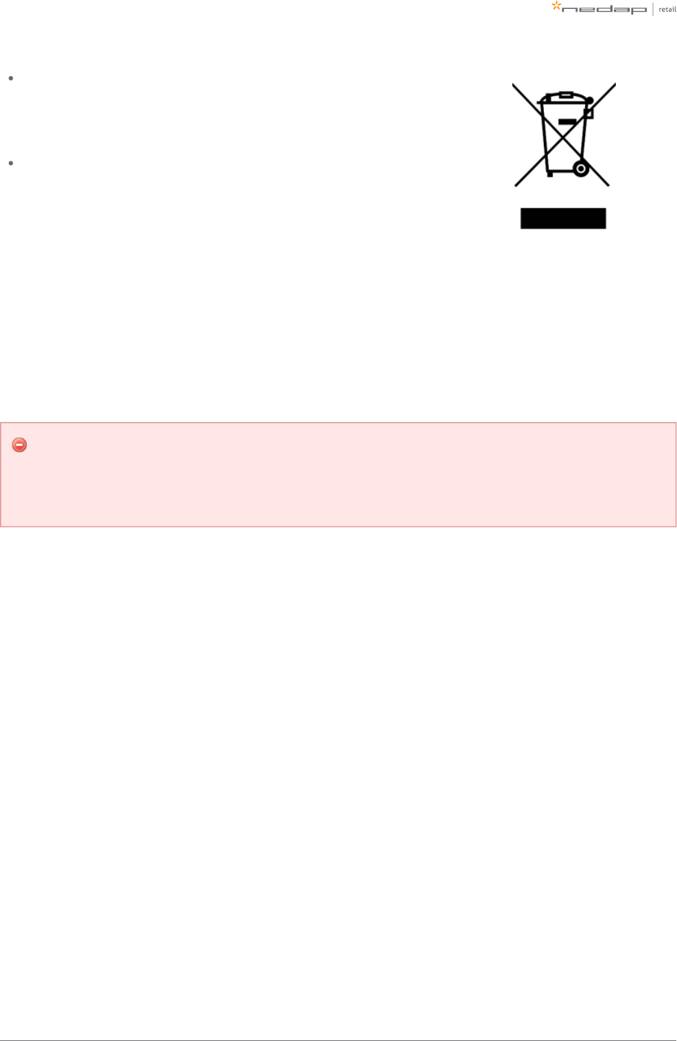
Battery disposal
This product contains a non-rechargeable lithium battery. Replace only with the same or equivalent type
recommended by the manufacturer (Panasonic CR2032 lithium button cell). At the end of its useful life, under
various state and local laws, it may be illegal to dispose of this battery into the municipal waste stream. Check
with your local solid waste officials for details in your area for recycling options or proper disposal.
Caution
Risk of explosion if battery is replaced by an incorrect type.
Dispose of used batteries according to the instructions.
Page of 7 55 Manual FLR-line
2 Product overview
There are multiple variations within the FLR-line that support different technologies, and upgrade kits that can
upgrade an 8.2 MHz RF installation to UHF RFID later on.
In this document the following abbreviations will be used from here onwards:
'RF technology' is an abbreviation for 8.2 MHz RF technology.
'RFID technology' is an abbreviation for UHF RFID technology.
Box contents
Article number Article name Box contents
9563873 ASSY FL30R RF GREY FL30 gate with Renos RF
Installation set
9563881 ASSY FL45R RF GREY FL45 gate with Renos RF
Installation set
9982124 ASSY FL45R RFID R1 GREY
FL45 gate with Renos, RFID reader and RFID antennas
3.5 m (11.5 ft.) RFID coaxial cable
Installation set
9982221 ASSY FL45R RF+RFID R1 GREY
FL45 gate with Renos RF, RFID reader and RFID antennas
3.5 m (11.5 ft.) RFID coaxial cable
Installation set
9982132 ASSY FL45R RF+RFID R2 GREY
9982159 ASSY FL45R RF+RFID R3 GREY
9982248 ASSY FL45R RFID R1 UPGRADE-RENOS
RFID reader and RFID antennas (only compatible with FL45 gate)
3.5 m (11.5 ft.) RFID coaxial cable
Installation set
9982302 ASSY FL45R RFID R2 UPGRADE-RENOS
9982175 ASSY FL45R RFID R3 UPGRADE-RENOS
It is not possible to combine different articles in one system.
Page of 8 55 Manual FLR-line
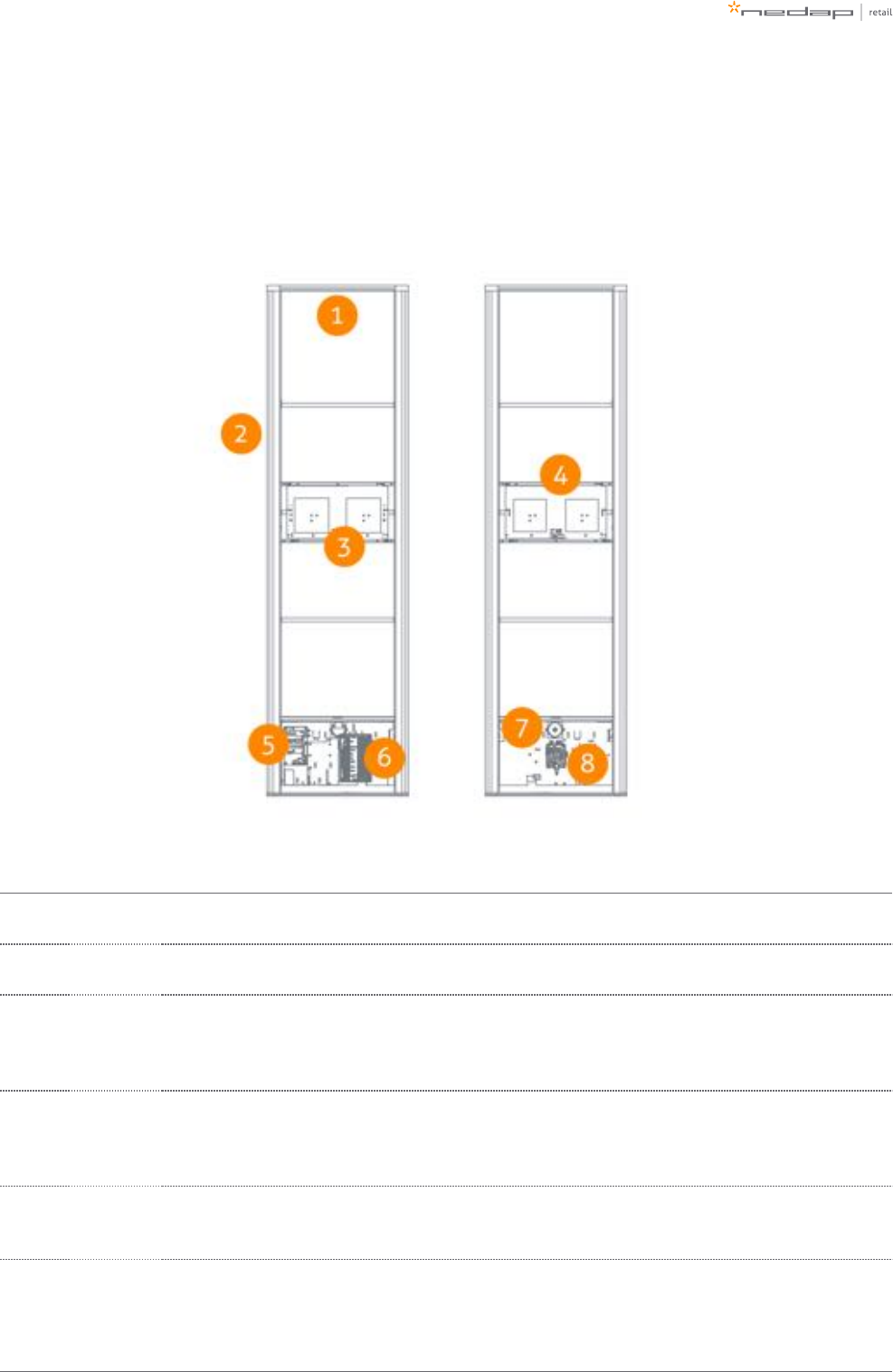
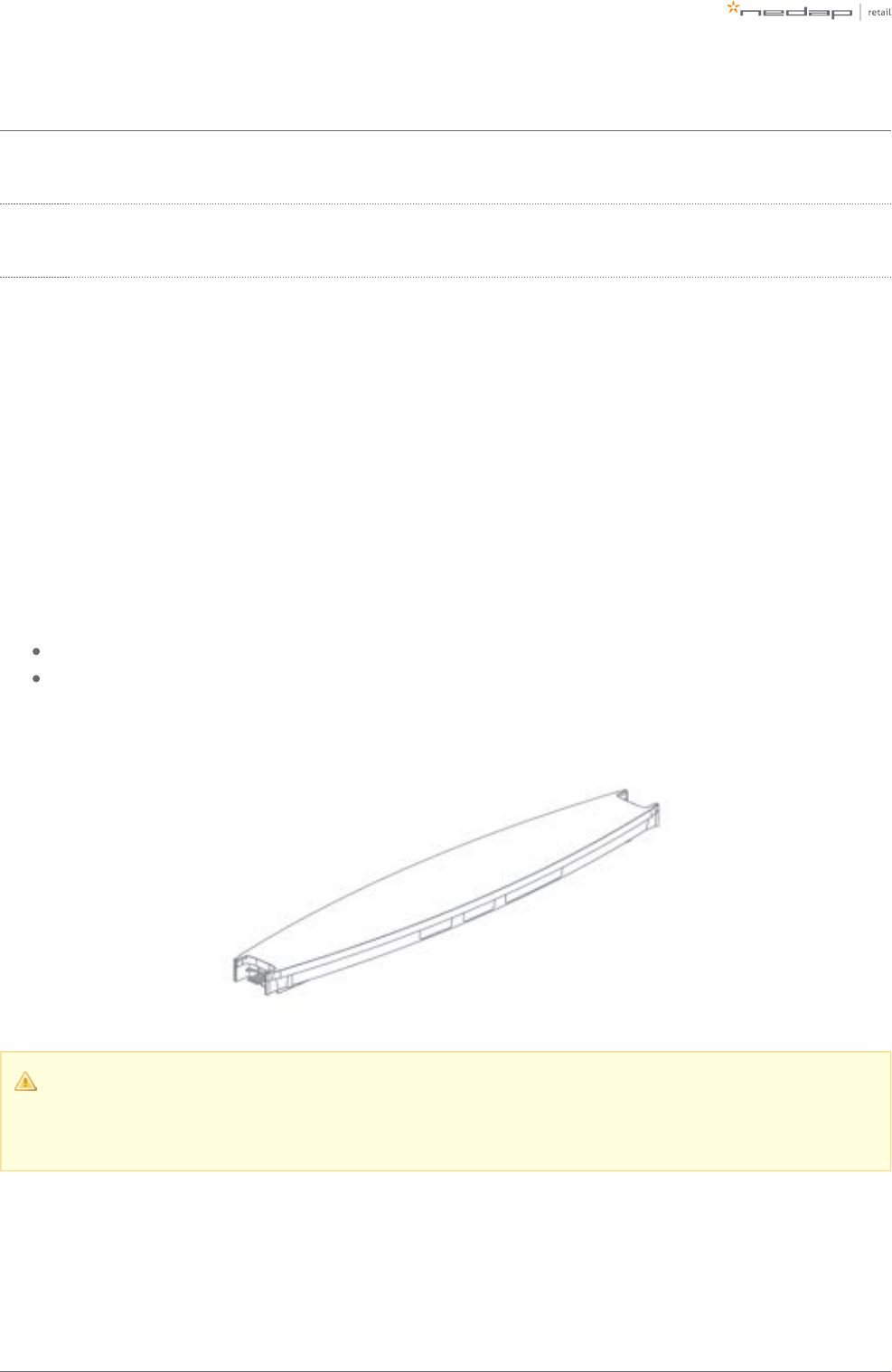
Components
The FLR-line of products are based on the Renos platform. The Renos platform is developed by Nedap Retail
specifically for retail applications. The FLR-line of products has several serviceable parts. These are explained
in the table and highlighted in the schematic drawings.
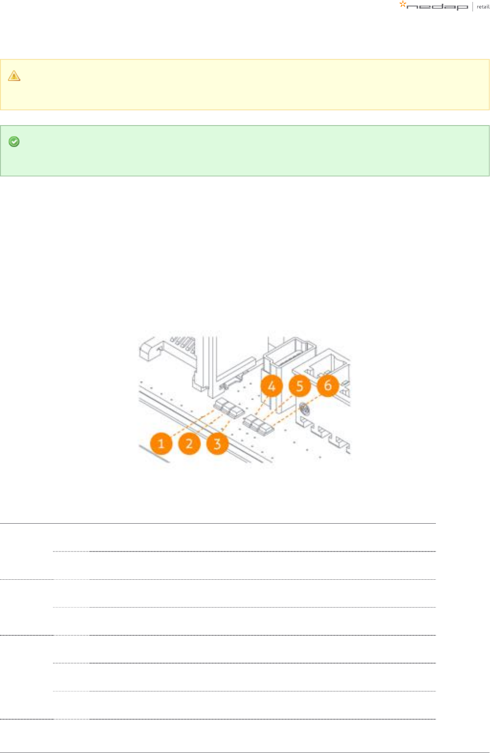
Number Component Description
1 Lights The red LED lights can be used for user feedback or alarms.
2 RF antenna The antenna is integrated in the aluminium frame.
3
RFID
antenna
NEXT
The RFID antenna, pointing to the NEXT gate (not included in all variations).
4
RFID
antennas
PREVIOUS
The RFID antenna, pointing to the PREVIOUS gate (not included in all variations).
5 RFID reader The RFID reader takes care of reading RFID labels. It is connected to the Renos unit, and to the RFID
antennas (not included in all variations).

Page of 9 55 Manual FLR-line
Number Component Description
6 Renos unit
The Renos unit is the main processing unit of an FLR product. It takes care of powering the system, data
communication between units and with the outside world. For most products it is equipped with an RF
detection engine - with the exception of the RFID-only systems used in Region 1 to be compatible with the
OST platform.
7 Buzzer The buzzer can be used for user feedback or alarms.
850 ohm
PCB The 50 ohm PCB takes care of the connection between the Renos unit, the RF antenna and the lights.

Page of 10 55 Manual FLR-line
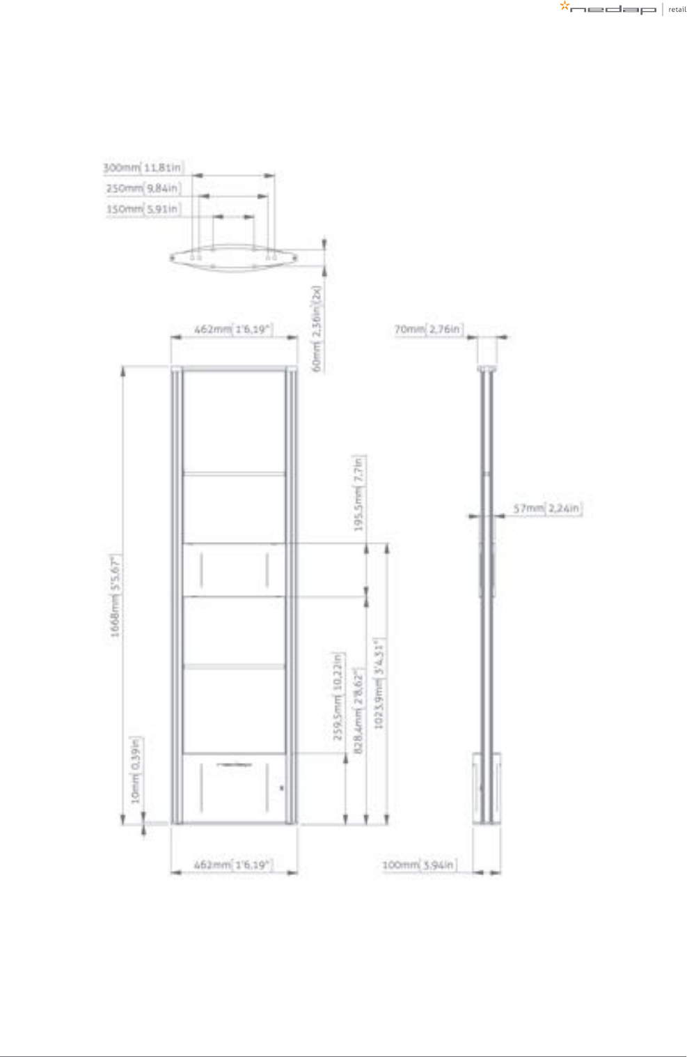
Dimensions
The dimensions of the gates can be found in the drawings below.
The pattern of holes in the mounting plate can be used to draw the right locations for drilling holes in the
floor.
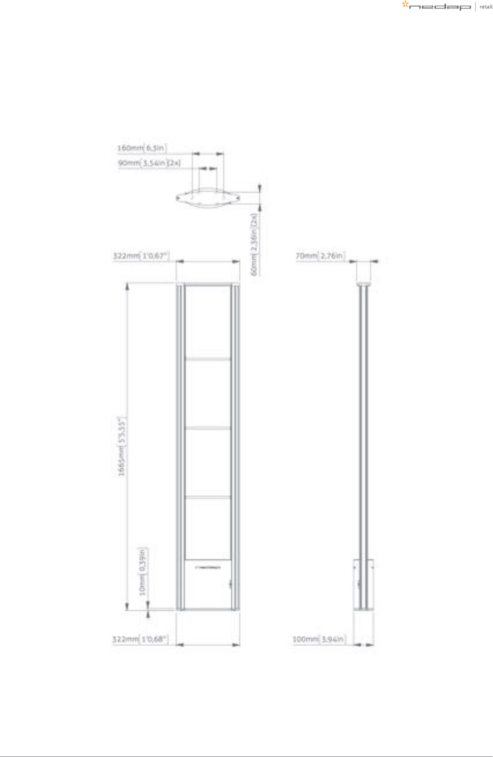
Page of 11 55 Manual FLR-line
FL30R
Page of 12 55 Manual FLR-line
FL45R
Page of 13 55 Manual FLR-line
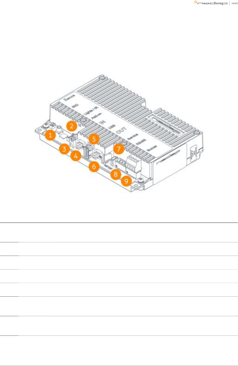
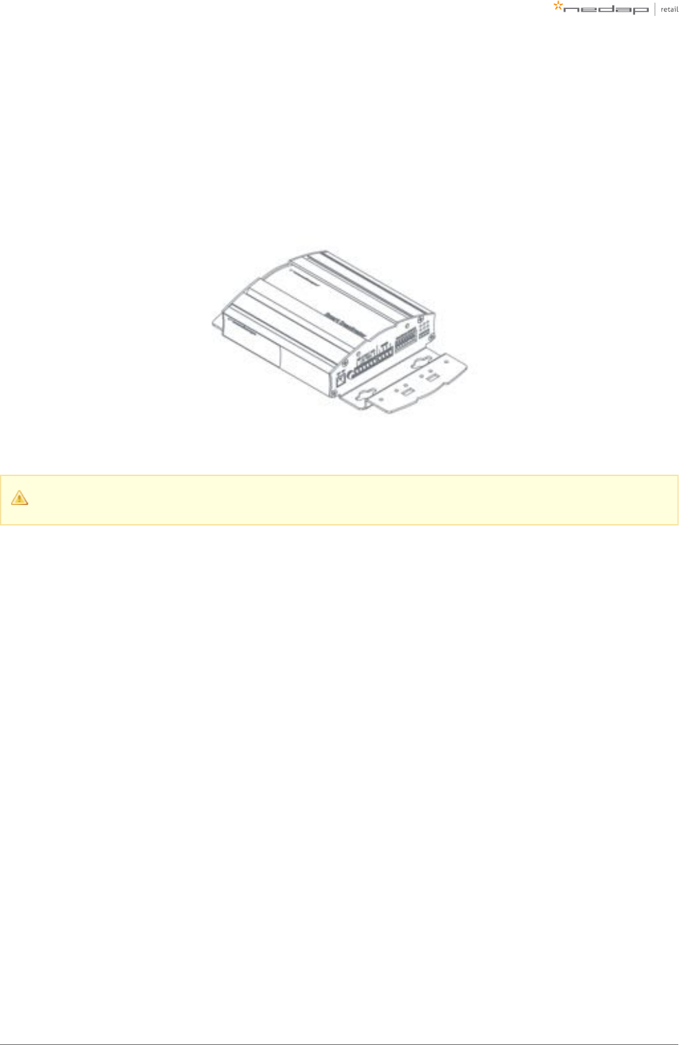
Connections
In the next picture a Renos unit is displayed, with a description of all its connectors and what they are used
for.
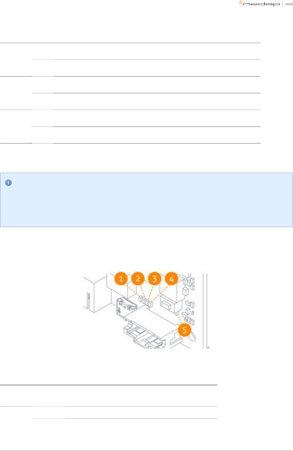
Number Connector Usage
1 50 ohm Connect the Renos unit to the 50 ohm PCB. The 50 ohm PCB connects both the light and the RF
antenna.
2 Infrared beams Connect to the optional infrared beam sensors.
3 Add-on Provide power and synchronization to add-ons, like the RFID reader.
4 Network IN Connected to the Network OUT of a previous Renos unit or a Power Inserter.
5 USB Connect accessories to Renos, like the RFID Reader.
6 Network OUT Connected to the Network IN of a previous unit or a Power Inserter. Can also be left unconnected or
connected to the customer network.
7Mini USB
service port Connect your laptop to configure the Renos system.
Page of 14 55 Manual FLR-line
Number Connector Usage
8RS485
connector Connect to the optional Nedap RF Smart Deactivator.
9Buzzer
connector Connect to the included buzzer.
The LED indicators on the Renos unit will be discussed later in this manual.
Add-ons
There are several add-ons available for the FLR-line products. The add-ons have their own manual, however,
we will discuss the function of those add-ons here.
Infrared beam sensors
Infrared beam sensors can be used for two purposes:
Customer counting in EAS role (both RF and RFID)
Direction detection when the system is used between stock room and sales floor (RFID only)
The infrared beam sensors can be easily 'clicked' in the FLR-line product.
Please note that if you want to use infrared beam sensors with a FLR-line product, ensure that every
gate in a group has sensors installed. It is not possible to only have sensors in the first and last gate
of a group.
Page of 15 55 Manual FLR-line
RF Smart Deactivator
The RF Smart Deactivator can be used to deactivate RF labels at the checkout. When connected to a Renos
system, it can be powered by a Renos system. The Renos system is also able to gather information from the
deactivator, like whether the deactivator is operational or not.
The RF Smart Deactivator cannot be used in systems where RFID is enabled.
RF security dashboard
The Renos platform has a built-in RF security dashboard. It can be enabled by entering a license key during the
configuration wizard. The customer can then visit the dashboard via the web browser. To make this work, the
Renos system should be either connected to the customer network, or a stand-alone set-up with a router
should be made.
Page of 16 55 Manual FLR-line
1.
2.
3.
3 Preparing the installation
When preparing an installation with FLR-line products, there are a few things that should be taken into
account:
How much gates you would need to cover an entrance or door
Where the gates will be placed in relation to the environment, to minimize interference (RF) and
reflections (RFID)
The number of Power Inserters that is needed to power the system
Which cabling needs to be installed
The firewall settings that need to be in place to enable Device Management
As those requirements differ based on which technology is used (RF, RFID or both), both technologies are
described in a different section.
Free-standing gates
If the gate is going to be free-standing in a super- or hypermarket environment, please take proper
precautions in terms of crash-protection. When customer guidance rails are available, you can use
those rails to protect the antenna against crashes by placing the antenna behind or after the
customer guidance rails.
When not available, use Nedap crash protection against shopping carts.
Defining the system
When a store requires gates to be placed at several locations, there needs to be a decision on how to combine
these gates into one or multiple systems. The following rules need to be taken into account:
A different role is a different system. It is not possible to combine gates for Electronic Article
Surveillance (EAS) with gates for stock room to sales floor in one system. Both roles need different
systems with their own Power Inserter and customer network connection.
Within the EAS role, create as large systems as possible. To minimize interference between gates, the
Renos platform has a built-in synchronization mechanism for both RF and RFID technology. For this
synchronization mechanism to work, the gates need to be connected in one system.
However, the maximum cable length requirements needs to be satisfied. If it is not possible to put all
the gates within a role in one system due to the maximum cable length requirements, you can split the
gates into two or more systems. In this case assign each system a different duringmulti-system channel
the RF configuration.
Page of 17 55 Manual FLR-line
Stock room to sales floor and goods receiving
For the stock room to sales floor and goods receiving roles: when there is a different door or
entrance, build a separate system.
It is not possible to combine gates with RFID and without RFID in one system. Either all gates should
have RFID, or no gates should have RFID.
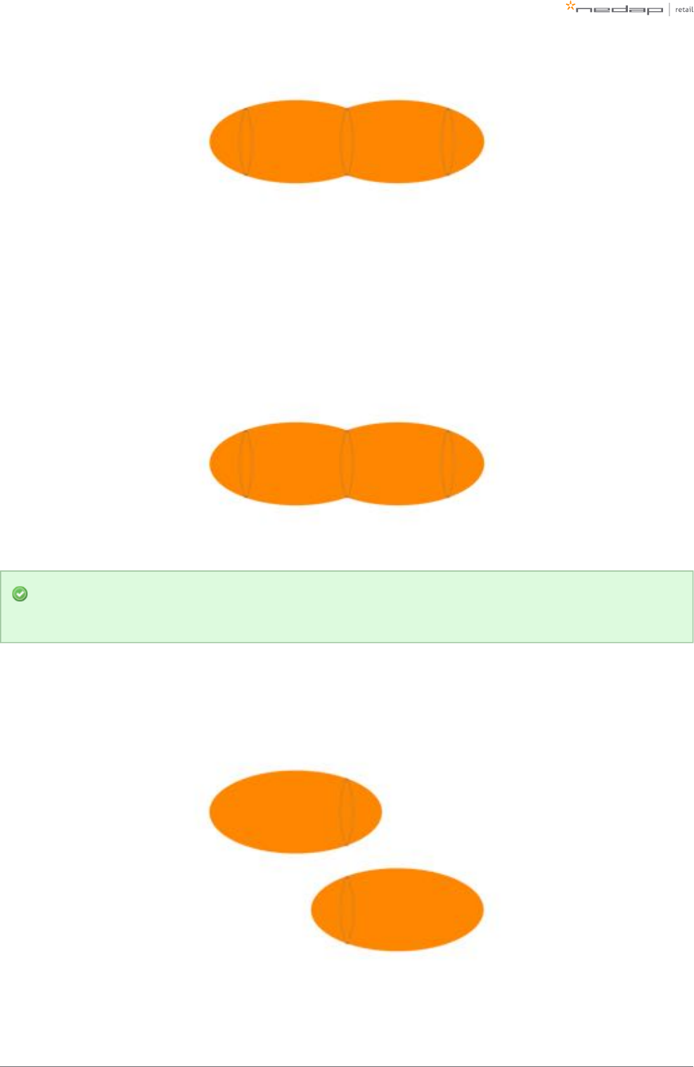
Field distribution
As RF and RFID are different technologies, their field distribution is different.
Field distribution for RF
There are two modes of operation for RF technology. The mode can be configured during the configuration
wizard.
With Edge Detection. There is a field around the gate. This mode is mainly used when the gates are placed
near the checkouts, as you can have one gate covering a relatively large area.
Infra-read beam sensors
Please note that when you want to use infrared beam sensors for customer counting, you can only
count customers in between the gates. So, if you enable Edge Detection, you are not able to count
customers outside of the gates.
There is a field in between gates. This mode is mainly used at the exit/entrance areaWithout Edge Detection.
of a store, as it is better to have antennas on the side, than in the middle of the passageway.
Page of 18 55 Manual FLR-line
Field distribution for RFID
In contrary to RF, with RFID the field is side-dependent. This means that there are two antennas inside each
gate, pointing to opposite directions. If there is more than one gate in a group, there is a detection field in
between gates. This is the default mode of operation.
If you combine both RF and RFID in one system, we recommend to disable Edge Detection. In this
way, the behaviour for both technologies is approximately the same.
If there is one gate in a group, it is not possible to make an aisle. To still have detection, you need to choose a
detection side of the gate. This can be either facing the previous gate or the next gate. This mode is mainly
used for small passageways, like with toilets.
Page of 19 55 Manual FLR-line
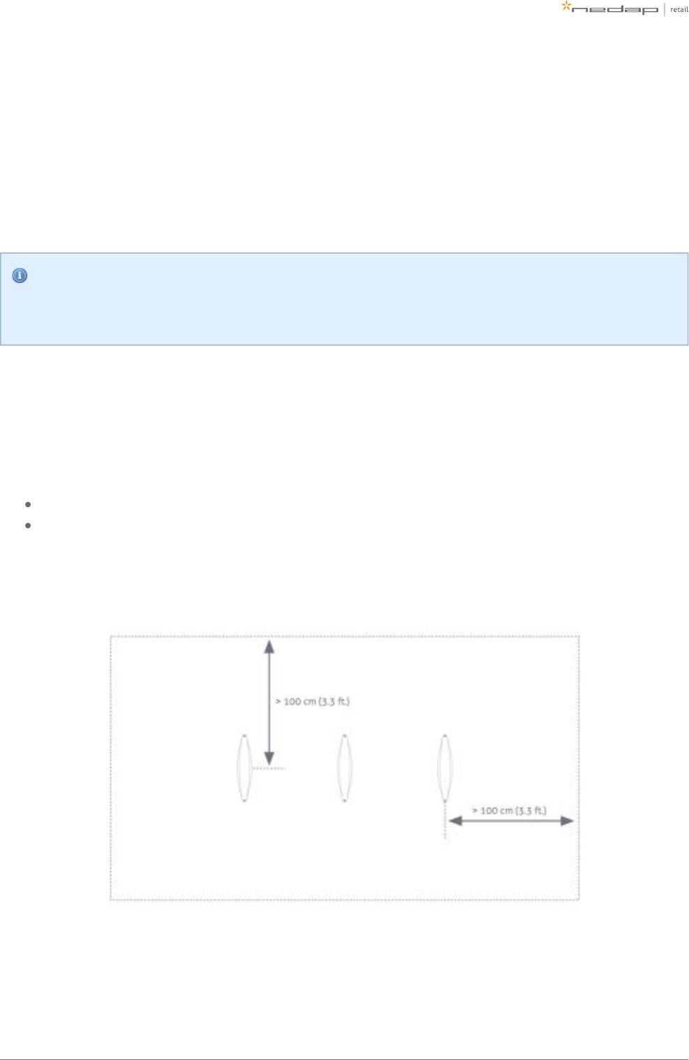
Detection distance, aisle width and label-free zone
The next step after understanding the field distribution, is understanding how many gates you need. This
depends on the detection distance (or aisle width) of the system. There is no fixed answer to this question, it
depends on many factors, like customer expectation, quality of the tags, the environment, etc.
The recommendations below are based on the Nedap NT4040 (reference label) for RF, and the Nedap RFID
hard tag (for RFID).
Please note that only the recommended 'detection distance' or 'aisle width' is specified. Depending
on the tag used and the environment the gates are placed in, sometimes larger values can be
achieved. It is advised to test this, before using it in a store.
Without RF Edge Detection or with RFID
We speak about 'aisle width' in this case.
When RF Edge Detection is disabled, the following recommendations are in place:
For the FL30R gate: an aisle width of 170 cm (5.6 ft.) is recommended.
For the FL45R gate: an aisle width of 200 cm (6.6 ft.) is recommended.
We recommend to have a label-free zone (both RF and RFID) of more than 100 cm (3.3 ft.) from the center of
the antenna.
Page of 20 55 Manual FLR-line
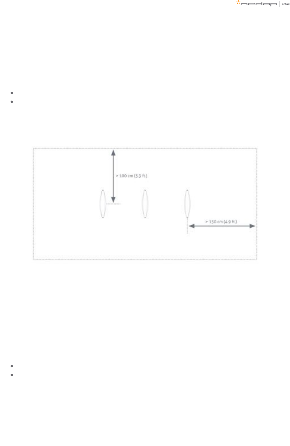
With RF Edge Detection (without RFID)
We speak about 'detection distance' in this case.
When RF Edge Detection is enabled, the following recommendations are in place:
For the FL30R gate: a detection distance of 85 cm (2.8 ft) is recommended.
For the FL45R gate: a detection distance of 100 cm (3.3 ft) is recommended.
We recommend to have a RF label-free zone of more than 150 cm (4.9 ft.) from the center of the antenna
behind the antenna, and 100 cm (3.3 ft.) into the store.
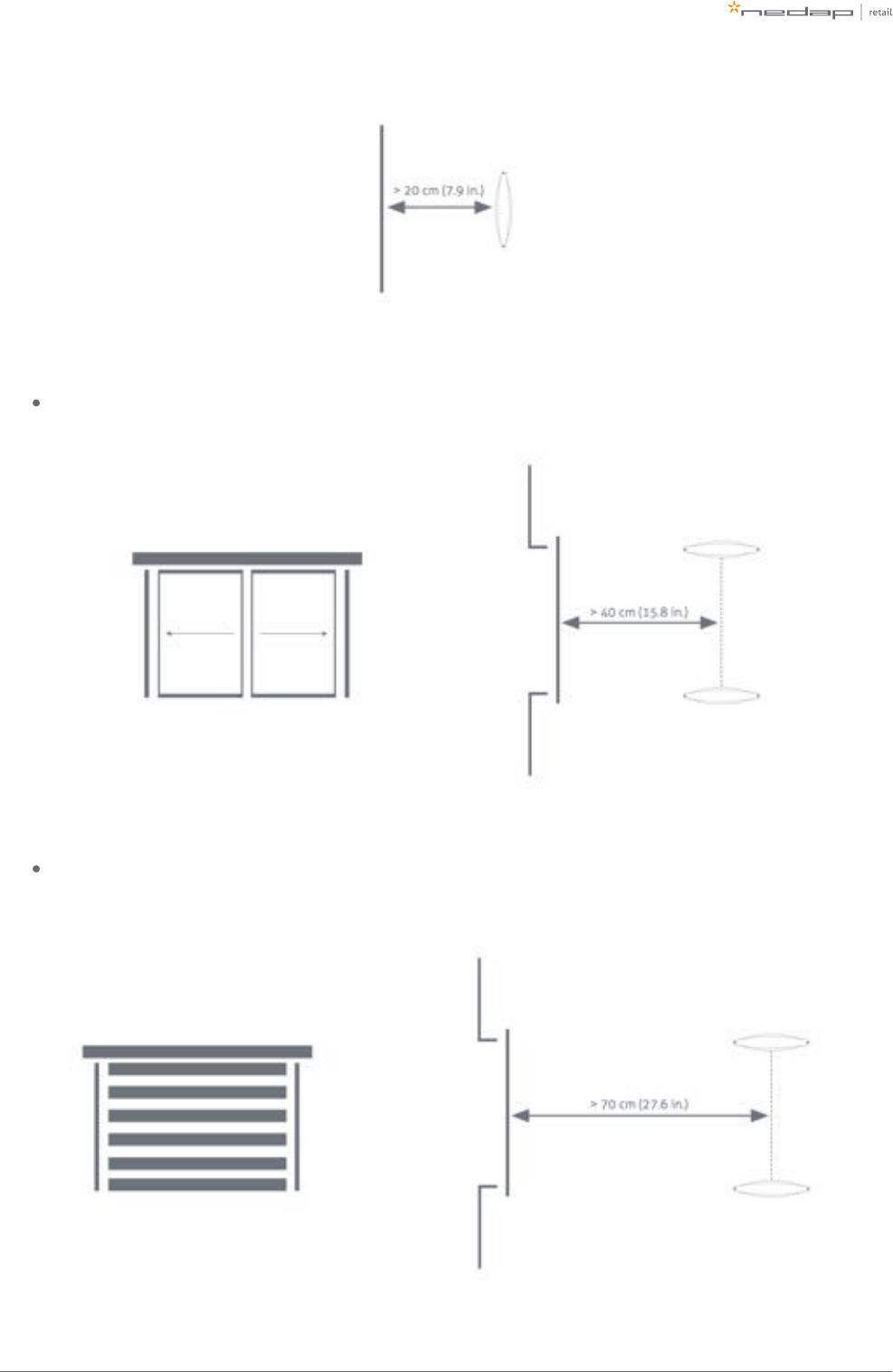
RF installation requirements
The operation of RF technology is affected by both coupling issues (the antenna couples with other objects)
and by active interferers (other devices that transmit a signal around 8.2 MHz). Objects that cause coupling
effects could be windows, doors, metal framing around the checkout, etc. Interferers can be created by
another RF system, but also motors driving doors or roller shutters.
Take the following placement requirements into account when projecting the location of gates:
There should be a minimum distance of 20 cm (8 in.) between the center of the gate and the wall.
There should be a minimum distance of 200 cm (6.6 ft.) between 8.2 MHz tags and/or labels and the
nearest antenna. If this is not possible, the labels and tags can be stored in a metal box in the checkout.
Page of 21 55 Manual FLR-line
In addition, when or are present:normal sliding doors
There should be a minimum distance of 40 cm (16 in.) between the center of the gate and the door.
In addition, when a is present: roller shutter
There should be a minimum distance of 70 cm (28 in.) between the center of the gate and the roller
shutter.
Page of 22 55 Manual FLR-line
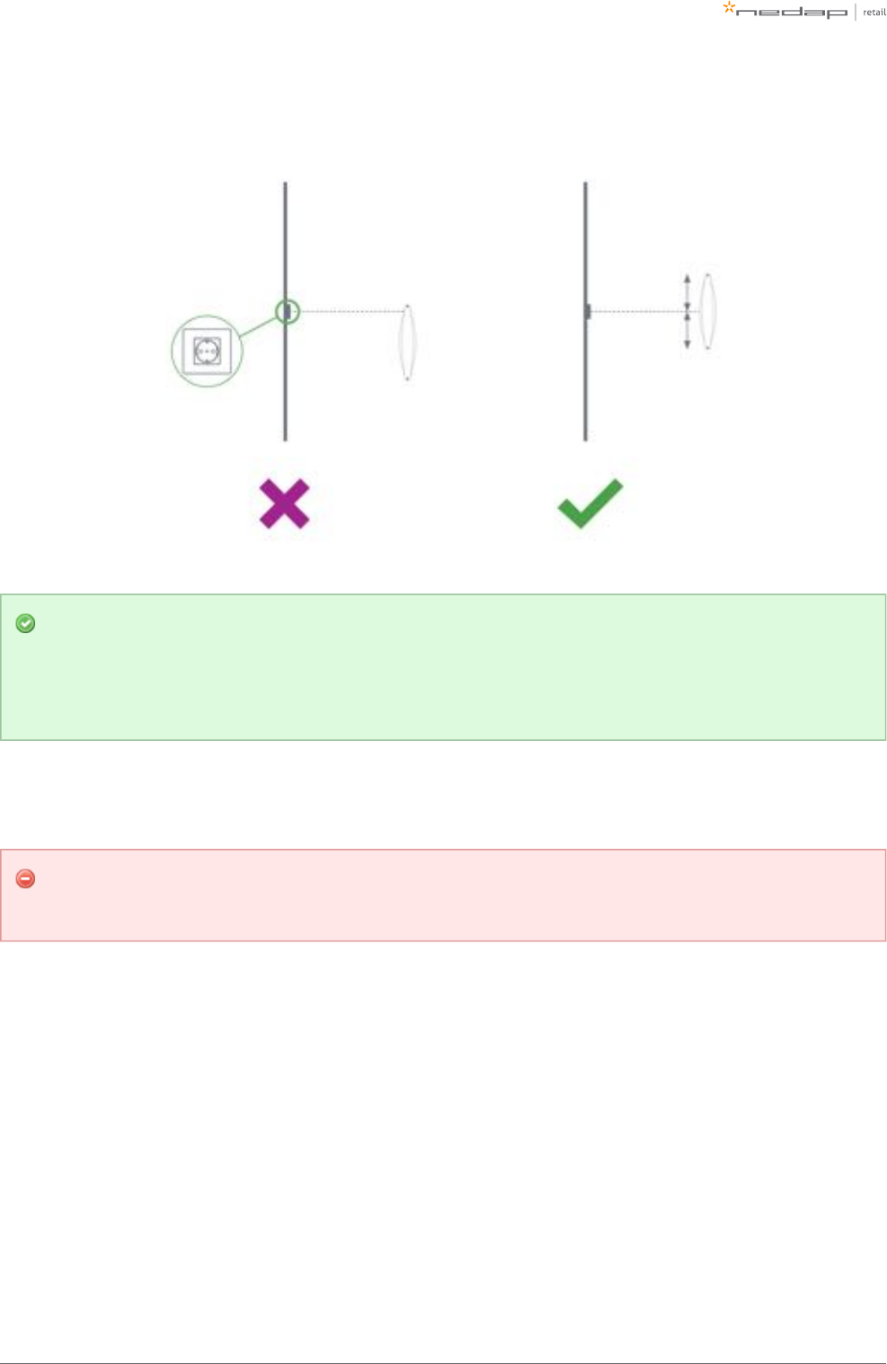
If a power socket is less than 50 cm (19.7 in.) from the gate, the center of the gate should be aligned with the
power socket.
Before the installation, it is advised to gain information on the flooring that is below the antenna. If a
dry-walk floor mat is used, it might have metal components that influence RF detection performance.
In that case a cut needs to be made in the floor mat to break conduction between the metal
components in the mat and the antenna.
When the antennas are placed right next to a checkout that contains significant metallic parts, we advise to
always use a shield.
To prevent interference and coupling issues, please make sure there is no conducting connection
between the gate and the checkout.
RFID installation requirements
When RFID technology is used, there are different installation requirements to consider than with RF
technology. Since the RFID field is much less strict defined than with RF technology, there is a larger area
where tags could be detected. In contrary to RF, RFID is much less sensitive to coupling or interference issues.
Page of 23 55 Manual FLR-line
Automatic tag muting
The RFID reader has a maximum read throughput of around 200 tag reads per second. This throughput is used
to monitor the status of the tags continuously. When many tags are placed close to or in the label-free zone, it
might be that the reader is 'too busy' with those tags, compared to other tags. This will impact the system
performance. If this happens, the reader will mute some tags, to have time remaining for other tags. This
feature is called . It might therefore be that some tags in the neighborhood of the systemautomatic tag muting
are muted, and will not cause an alarm when moved through the gates.
Metallic surfaces
As the RFID field is reflected by metallic surfaces, this might confuse the Dynamic Beam Steering algorithms
and influence (change or enlarge) the detection field. That is why we advise to avoid large metallic surfaces
(larger than an A3/Tabloid sheet of paper) in the neighborhood of RFID-enabled gates.
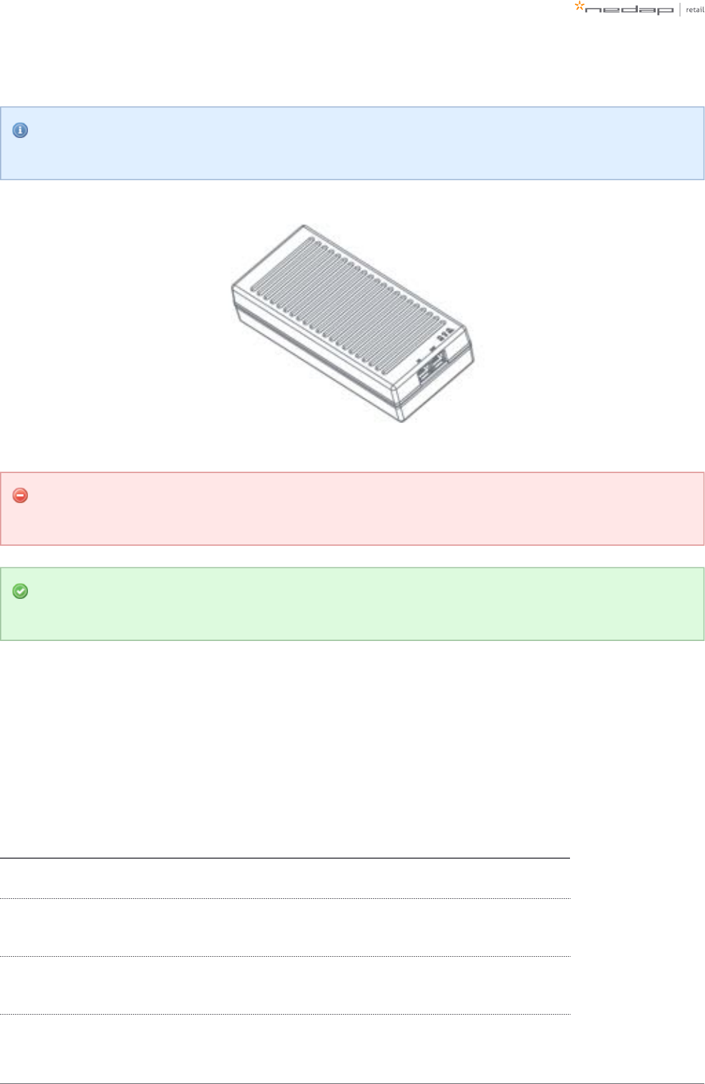
Power Inserter
When the installation location of the products is clear, the location of Power Inserters needs to be defined.
There is a maximum number of Renos units that can be connected to one Power Inserter, depending on which
technologies are used and the number of add-ons that are in use.
Technologies and add-ons in use Number of Renos units per Power Inserter
230 V 115 V
8.2 MHz RF 6 5
8.2 MHz RF and 1 or 2 Smart Deactivators per unit 5 4
RFID 6 5
8.2 MHz RF and RFID 4 3
8.2 MHz RF and RFID and 1 or 2 Smart Deactivators per unit 3 3
Upgrading to RFID
If there is any chance that the retailer wants to upgrade an 8.2 MHz RF system to RFID later on,
please take the power requirements for RFID already into account. So instead of having 6 (230 V) or
5 (110 V) units on one Power Inserter - use just 4 (230 V) or 3 (110 V) units on one Power Inserter.
Page of 24 55 Manual FLR-line
Of course, it is also possible to put less Renos units on a Power Inserter.
Please note that you can only use a Nedap Power Inserter (Power-over-Ethernet) to power Renos
systems. It is not possible to use generic Power-over-Ethernet switches or stand-alone inserters.
Make sure the Power Inserter is placed at least 1 m or 3.3 ft. from the gates. When placed closer to
the gate, it might cause interference on the RF technology.
It is recommended that the Power Inserter is connected to an always-on power socket. This allows
continuous monitoring of the system, and remote firmware update during the night.
Cabling
When the number of gates and the number of Power Inserters is clear, the next step is to determine the
cabling to be used for the system. Depending on the technologies that are used, different cables are required.
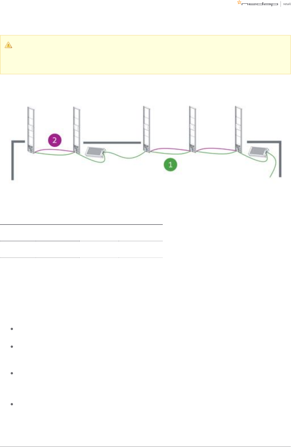
The FLR-line uses a daisy chain topology, which means that all devices are connected as a chain: a cable from
a Power Inserter OUT to a Renos unit IN, from that Renos unit OUT to the next Renos unit IN, etc.
Technologies in use Cables that need to be installed
Only RF Ethernet cable between each unit and the Power Inserter
Only RFID Ethernet cable between each unit and the Power Inserter
RFID Coaxial cable (included with the product) between each unit in the same group
Both RF and RFID Ethernet cable between each unit and the Power Inserter
RFID Coaxial cable (included with the product) between each unit in the same group
Page of 25 55 Manual FLR-line
If the system should be connected to the customer network or Device Management, there also needs to be an
Ethernet cable from the system to the customer network or a 3G/4G router.
Ethernet cable
The maximum data communication length for an Ethernet cable is 100 meter (328 ft.). Therefore we
recommend the following maximum distances:
The maximum cable length in between two Renos units is 100 meter (328 ft.) - even if there is a Power
Inserter in between.
The maximum cable length from the Power Inserter to the last Renos unit powered by that Power
Inserter is also 100 meter (328 ft.)
When the cable lengths allow for it, we recommend to place the Power Inserter in the switch room. In
this way the customer only has to arrange an Ethernet outlet near the installation, and no power
sockets are needed. This could reduce the cost for installations significantly.
When a connection to the customer network is to be made for local access or Device Management, this
connection can be made from:
The customer network to the IN port of the Power Inserter.
The customer network to the OUT port of the last Renos unit in the chain.
The exact location needs to be configured during the configuration wizard.
Ethernet cable type
Please use Ethernet Cat. 5 cable or better with all 8 pairs connected.
RFID coaxial cable
The RFID coaxial cable that is supplied with the product has a length of 3.5 m (11.5 ft.). As the quality of this
cable strongly influences the performance of the system, the cable is supplied together with every FLR-line
gate from Nedap. It is not possible to use 3rd party cables.
RFID coaxial cable placement
It is only necessary to install the RFID coaxial cable between units in the same group. It is not
necessary to connect a RFID coaxial cable between groups.
Page of 26 55 Manual FLR-line
The RFID coax cable has a fixed length of 3.5 m (11.5 ft.) to minimize signal loss. If the cable is not
run through a slit, but through a basement or other conduit please check whether the path is not
longer than approximately 2.5 m (8.2 ft.).
Cable number Type of cable Required for RF Required for RFID
1 Ethernet cable Yes Yes
2 RFID coaxial cable No Yes
Device Management
All the Renos-based products can be connected to the Nedap Device Management Service. This service
provides:
Monitoring. Critical system parameters are monitored 24/7. As soon as something is wrong with the
system, an alert is generated to the supporting partner.
Remote log-in. Via the Device Management portal it is possible for an authorized Nedap-certified
engineer to access the user interface of the system to make changes to the configuration or access
system logs.
Firmware update. It is possible to install new firmware releases remotely.
To use Device Management, please make sure that the following firewall ports are opened before installation:
TCP port 443 outgoing to *.nedapretail.com

Page of 27 55 Manual FLR-line
This can be verified by connecting your laptop to the customer network, open your browser and navigate to
. You should see a special page there.https://api.nedapretail.com
It is also possible to do this via an HTTPS proxy, however, the remote log-in feature is not available then.
For more details, please see the Knowledge Base article on Device Management.
If Device Management is available at a certain site, it is possible to pre-configure a system, such that
the field engineer will have an easier job. For more information, please refer to the Knowledge Base
article on Pre-configuration.
Page of 28 55 Manual FLR-line
4 Executing the installation
When all the preparations are taken into account, the installation of the system can take place. The installation
consists of physically mounting the system in the right orientation, installing the cabling and applying power
to the system.
Conduit or slit
We always advise to place a conduit, as this allows easy replacement of cables when necessary. If not
possible, a slit can be made as well.
When a system is going to be upgraded to RFID in the future, please make sure to install a conduit to
add the RFID coax cable in the future. You can also choose to install the RFID coax cable already. This
is especially important when relying on a floor cut.
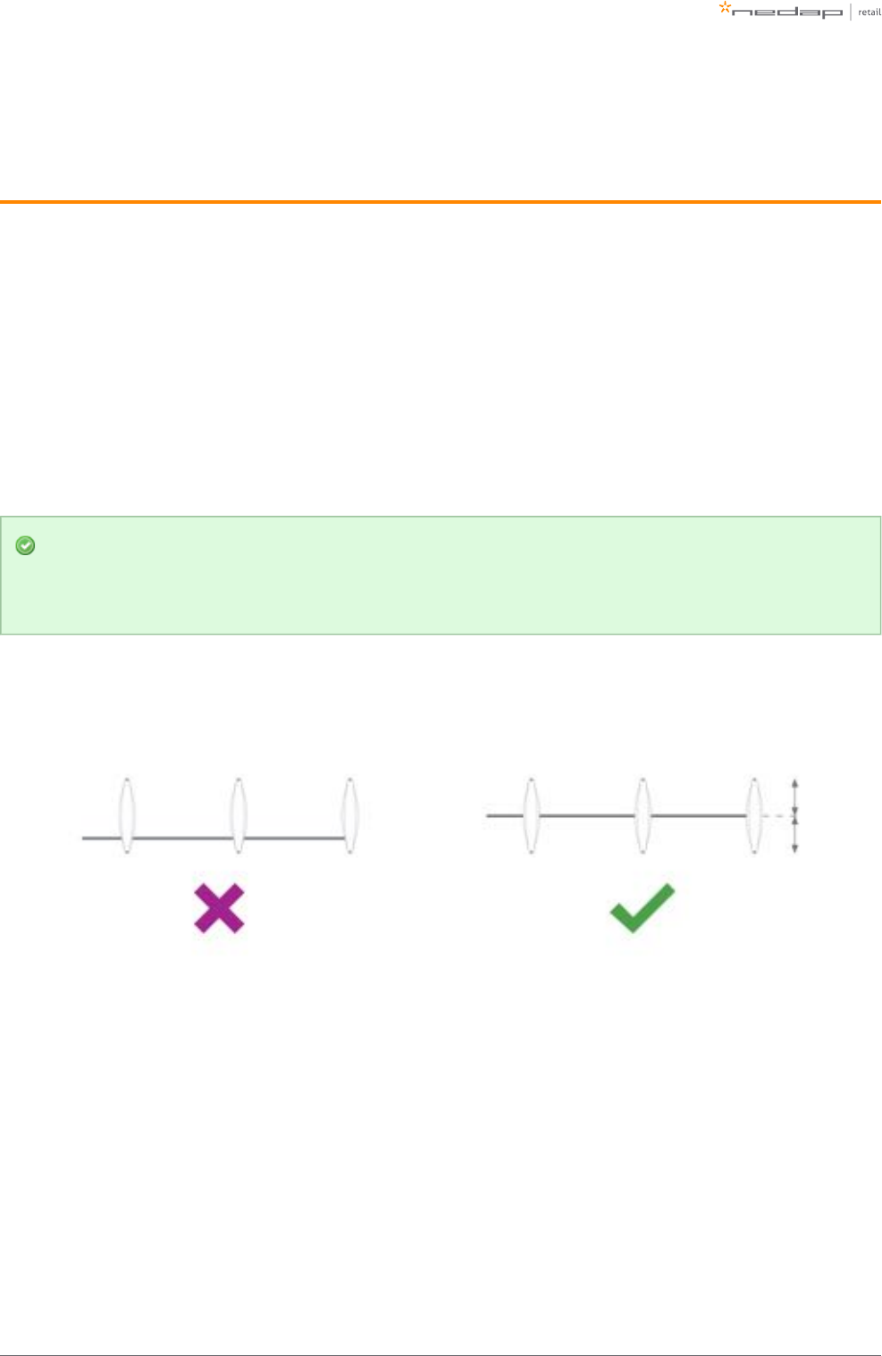
The conduit or slit in which the cables are placed, should be exactly in the middle of the antenna,
perpendicular to the antenna. This is explained in the following pictures.
Page of 29 55 Manual FLR-line
1.
2.
3.
Physical installation
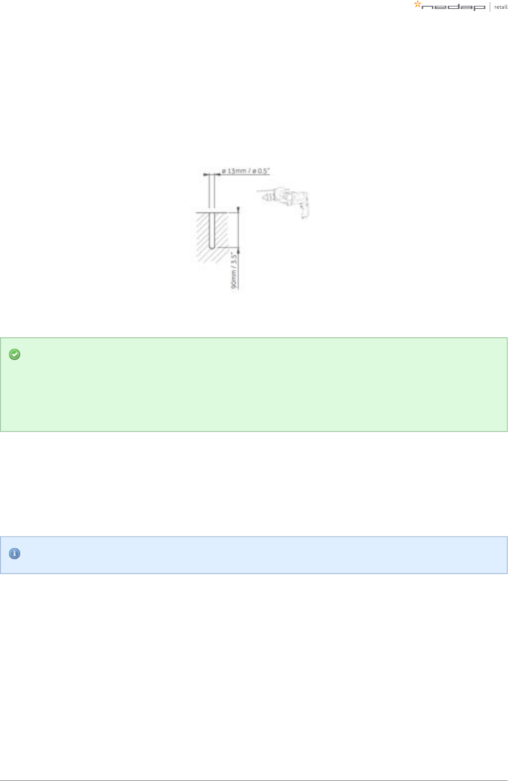
Make sure the right locations of the holes are marked on the floor, according to the dimensions sketched
earlier in this document. Drill the holes.
Placing a gate close to a wall
If RF technology is to be used: always keep enough space to place a shielding afterwards. You will
only know whether you need shielding when you are configuring the system (for example when you
find too much interference during the configuration).
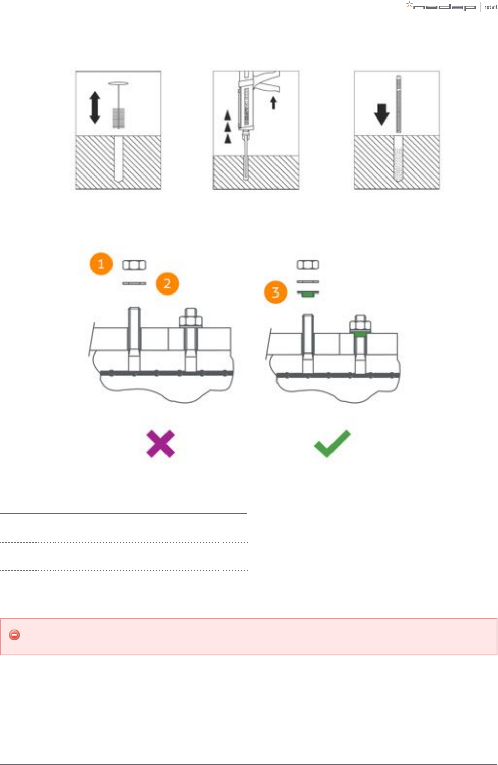
Then follow these steps to place the nuts.
Clean the hole.
Insert Hilti-hit.
Place the nut.
Hilti-hit and the nut are not included in the installation set.
Page of 30 55 Manual FLR-line
Always use a nylon insulation ring to insulate the gate from the floor.
Number Description
1 Nut M10 (not included in installation set)
2 Retainer ring M10 (not included in installation set)
3 Nylon insulation ring M10 (included in installation set)
If the gate is not properly isolated from the floor, this might cause RF interference issues.
Page of 31 55 Manual FLR-line
1.
a.
b.
2.
a.
b.
c.
3.
Orientation of products
Due to the orientation-sensitivity of the RFID antennas, the gates all need to be oriented in the same way. To
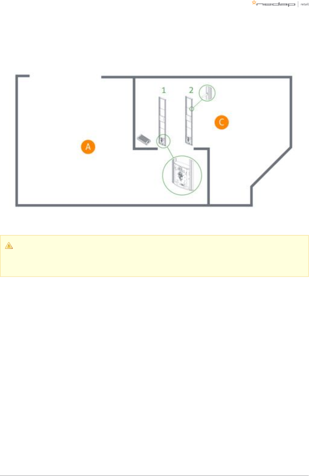
make sure this happens, please follow the listed steps in order:
Place all gates with the infrared beam sensors connector facing towards the customer entrance/exit of
the store.
For the stock room to sales floor and goods receiving role: this also holds here - the gates should
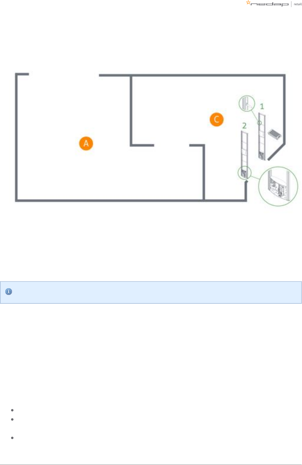
not face the goods delivery entrance/exit of the store. See the example below.
For the EAS role, when you need to secure a toilet: the toilet is considered as the customer
entrance/exit of the store. See the example below.
Find gate number 1.
To find gate number 1, find the sticker on the footplate of the gate that indicates the IN/prev and
OUT/next direction.
The flow is from the OUT of one gate, to the IN of the next gate.
Follow the IN backwards, until you have arrived at the first gate. That is gate number 1.
The OUT of the Power Inserter should be connected to the IN of gate number 1.
If this procedure is not executed correctly, the RFID technology will not work.
In the following examples, the location types in the table below occur.
Letter Location type
A Sales floor
B Toilet
C Stock room
Page of 32 55 Manual FLR-line
Example of EAS role
Page of 33 55 Manual FLR-line
Example of EAS role, with toilet
Page of 34 55 Manual FLR-line
Example of stock room to sales floor role
Please note that when you compare stock room to sales floor role to EAS with toilet, the orientation
of the gates is exactly opposite! This is due to the fact that all gates should be facing the customer
entrance/exit of the store, with the exception of the toilet.
Page of 35 55 Manual FLR-line
Example of goods receiving role
Installing cabling and filters
During the preparation phase, the exact cabling required was already determined. Now these cables can be
placed.
All wiring should be done according to local regulations.
When cables are put in the slit or conduit, it is recommended to mark them with IN and OUT, or PREVIOUS and
NEXT, as this will allow you to distinguish them from each other.
Filters
Please note that filters should be placed around the cables to reduce interference with other systems. These
filters are delivered together with the system.
Filter should be placed at:
Every Power Inserter: around the Ethernet cable, both at the OUT and IN port.
Every Renos unit: around the Ethernet cable and the RFID coaxial cable (when used), both at the OUT
and IN port.
Every 9 m (30 ft.) for longer Ethernet cables.
Page of 36 55 Manual FLR-line
To save yourself a huge amount of frustration, please first place the filters attaching thebefore
connectors. The other way around is not possible. Many have tried before.
Filters can be ordered as spare part with Nedap. Please refer to the Nedap Retail Portal for more
information.
The filters that are close to a Renos unit should be placed inside the foot of the gate. If there are multiple
filters in the electronics are of the gate, they should be tied together.
Ethernet cables
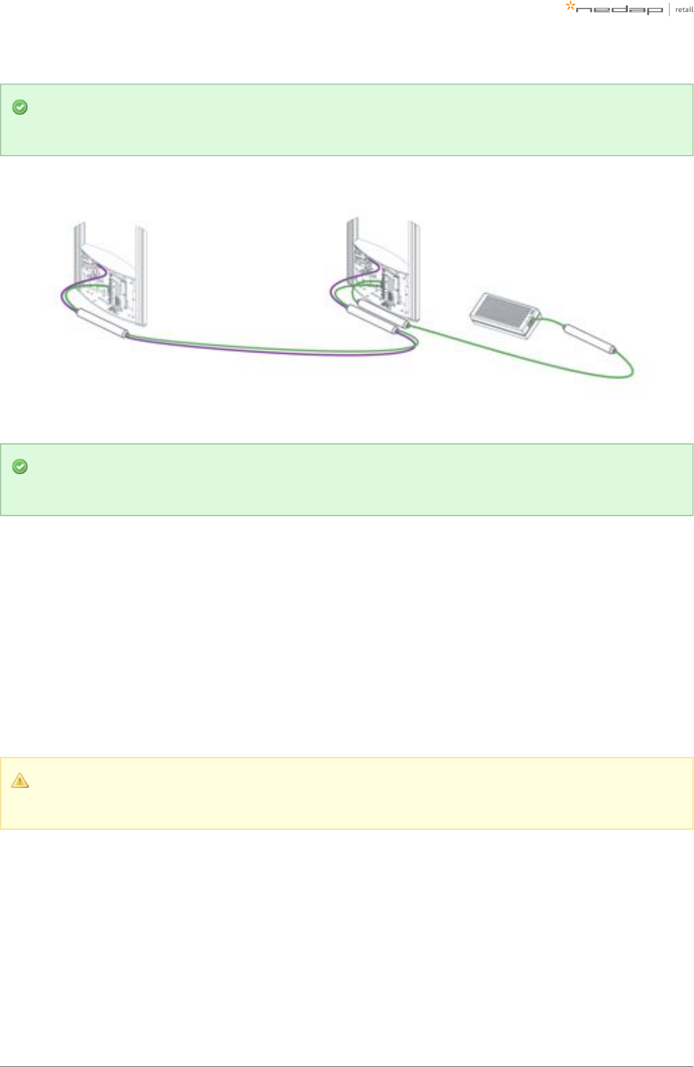
Connect the Ethernet cable from the OUT port with the IN port of the next Renos unit
First, in all aisles connect the Ethernet OUT port with the IN port of the next Renos unit, always following the
directions of the arrows in the cabling indicated by the image below.
Please make sure to test every Ethernet cable for correct connections and twisting of all 4 pairs (8
wires) with an Ethernet cable tester. This is to make sure that the system can function correctly.
RFID coaxial cable
If the Ethernet cable is connected, connect the RFID coaxial cable in the same way. Connect from Gate 1 (next)
to Gate 2 (previous), from Gate 2 (next) to Gate 3 (previous), etc.
The RFID coaxial cables should be connected from the NEXT port of one reader, to the PREVIOUS port of the
second reader. PREVIOUS and NEXT are related to the order of units in relation to the first Power Inserter.
Page of 37 55 Manual FLR-line
Please make sure that you don't make sharp bends in the RFID coaxial cable. This will have a
negative impact on the performance of the system.
Don't use a tool to tighten the RFID coaxial cable connectors. This is not necessary and might break
the connectors. If the connector is tightened by hand, that is good enough.
Status LEDs
The electronics inside the unit has several status LEDs that can be used to discover the status of each part of
the electronics.
Renos unit
Led Color Status Explanation
1 Green
On There is a Renos unit connected to the OUT port of this unit
Off There is Renos unit connected to the OUT port of this unitno
2 Blue
Blinking There is device connected to the OUT port of this unitno
On There is a Power Inserter connected to the OUT port of this unit
3 Red
On There is an issue with the power supply at the OUT port of this unit (too little current drawn)
Blinking There is an issue with the power supply at the OUT port of this unit (too much current drawn)
Off There is issue with the power supply at the OUT port of this unitno
Page of 38 55 Manual FLR-line
Led Color Status Explanation
4 Yellow
Blinking The operating system on the Renos unit is running
Off The operating system on the Renos unit is runningnot
5 Green
Blinking The storage flash on the Renos unit is accessed
Off The storage flash on the Renos unit is accessednot
6 Green
On The firmware on the Renos unit is running
Off The firmware on the Renos unit is (yet) runningnot
Please refer to the Troubleshooting chapter later in this manual to resolve erroneous conditions.
Firmware error
If the Renos unit has a firmware error, the rightmost three LEDs (4, 5 and 6) will remain off when the
unit is powered. This can be solved by using a 'Local - single unit' firmware update, as is described
later on in this manual.
RFID reader
Led Color Status Explanation
1
Blue
On
The RFID Reader is connected to the Renos firmware
Blinking The RFID Reader has received a command from the Renos firmware
Page of 39 55 Manual FLR-line
Led Color Status Explanation
Off The RFID reader is connected to the Renos firmwarenot
2 Orange
Blinking slow The firmware on the RFID Reader is running
Off The firmware on the RFID reader is runningnot
3 Red
On There is an error with the RFID output
Off There is error with the RFID outputno
4 Green
On The RFID output is active
Blinking The reader is reading RFID labels
Off The RFID output is activenot
5 Green
On The RFID reader is powered by the Renos unit
Off The RFID reader is powered by the Renos unitnot
Status of LEDs before configuration
When the system is not configured yet, the RFID reader will not be active. This means that only the
'firmware running' orange LED is blinking.
Page of 40 55 Manual FLR-line
5 Configuring the installation
To complete the configuration, the following tools are required.
Mini-USB cable.
Laptop with installed driver (if necessary) and recent browser.
Driver installation
To configure a Renos-based system, sometimes a driver needs to be installed. Please check the table below
whether you need to install a driver, based on your operating system.
Operating system Driver
Windows XP, Vista or 7 Download from portal
Windows 8 No need to install driver
Mac OS X No need to install driver
Linux No need to install driver
Once you have installed the driver, check if it works by plugging-in a Renos unit.
Recent browser
To configure the system, an HTML5 compatible browser should be installed on your laptop. The following
browsers (or higher) are officially supported:
Google Chrome
Mozilla Firefox 6 (or higher)
Apple Safari 6 (or higher)
Microsoft Internet Explorer 9 (or higher)
If you don't have one of these browsers installed on your laptop, please install them now.
Page of 41 55 Manual FLR-line
Connecting a laptop to the Renos unit
You can connect your laptop via a Mini-USB cable to the service port on the Renos unit. You can choose any
Renos unit in the system.
It is advisable to use a long USB cable. This is more comfortable as you can find a good place to put
your laptop (instead of on top of stairs, or on the floor next to the antenna). Besides, some laptops
cause interference on the RF technology, so it is better to place them further away.
We advise to use a ferrite ringcore filter around the mini USB cable that is used to configure Renos.
These can be ordered as spare part with Nedap. Please refer to the Nedap Retail Portal for more
information.
Entering the configuration wizard
You can enter the configuration wizard by opening your browser, and navigating to:
http://192.168.133.1
Authentication
During the configuration, the user is required to authenticate himself. How this is done, is dependent on the
Device Management availability.

Page of 42 55 Manual FLR-line
1.
2.
3.
4.
a.
b.
c.
5.
6.
7.
The system is connected to Device Management: you can directly enter your Nedap Retail username
and password.
The system is not connected to Device Management, and you don't have a Nedap Retail authentication
software or hardware dongle: choose one of the following steps:
If your laptop is able to connect to Device Management via a 3G dongle or Wi-Fi, you can use
this option to enter your username and password.
If that is not available, you can use your smartphone.
If your smartphone has no internet access, you can call our support to get an authentication
code.
Please contact support for more details on how to obtain a Nedap Retail username and password.
Getting help in the wizard
If something is not clear, each page has a question mark button in the top right corner. You can click this to get
more information on what is expected to do on a certain page.
Firmware version and System ID
When you ask for support for a specific system, the support engineer will always ask you for the firmware
version and the system ID. The firmware version is displayed in the right top of the configuration wizard. If you
click the firmware version, a pop-up will appear that shows the System ID.
Factory reset
To execute a factory reset on a single Renos unit, the following steps need to be executed:
Turn off the system by removing the power cable of the Power Inserter.
Connect a Mini-USB cable from the USB service port to the USB port on the Renos unit.
Reconnect the power cable to the Power Inserter.
The LED that usually indicates that the firmware is running (the green LED on the right) will show the
following behaviour:
Blink couple of times
Stay on
Blink couple of times
When this is completed, wait one minute before proceeding.
Turn off the power.
Remove the USB cable.
Turn on the power.
Page of 43 55 Manual FLR-line
1.
2.
3.
Configuration is lost
Please note that when doing a factory reset, all settings and configuration of the unit are lost. The
firmware version does not change.
Firmware change
There are three ways to change the firmware version on a Renos-based system:
Device Management update. The update can be executed via the Device Management service.
Local - single unit flash. The update can be executed by inserting a USB stick with the right firmware
into the USB port.
Local - complete system flash. The update can be executed during the configuration wizard with files
on your laptop.
If the system is integrated with a 3rd party system, please confirm the firmware version with that 3rd
party before installing it.
Device Management update
To update the firmware via Device Management, please make sure the system is configured, delivered and
connected to the Device Management service. Then, navigate to the Device Management website and use the
functionality there to initiate the firmware update.
Local - single unit flash
Download the correct firmware image file from the Nedap Retail portal. Extract this file to a USB stick. Turn off
the power of the system. Insert the USB stick in the USB port of a Renos unit. Power the system. Wait until
LEDs 4, 5 and 6 are off again. This can take around ten minutes. Then turn off the power again, remove the USB
stick and turn on the power.
Configuration is lost
Please note that when using 'local - single unit flash' firmware change, all settings and configuration
of the unit are lost.
It's only possible to execute this on-site and not remotely, as the system needs to be re-configured
before it is usable again.

Page of 44 55 Manual FLR-line
Local - complete system flash
Download the correct firmware image file from the Nedap Retail portal. Enter the configuration wizard and
accept all Renos units in the system that should be updated. Press the Advanced button and follow the steps
to change the firmware. One of these steps is to upload the firmware image file.
Configuration is lost
Please note that when using 'local - complete system flash' firmware change, all settings and
configuration of the system are lost.
It's only possible to execute this on-site and not remotely, as the system needs to be re-configured
before it is usable again.
Page of 45 55 Manual FLR-line
6 Integrating the installation with other
systems
It is highly recommended to integrate the FLR line product into other solutions in use at the end customer.
Software integration with API's
The Renos platform offers several API endpoints that deliver events. Those events include:
RFID reads
RFID movements
RF alarms
RFID alarms
Infrared beam sensor events
For more information please refer to the Software integration page on the Nedap Retail portal with
documentation and examples.
Physical integration using an IO Box
It is also possible to integrate other systems via relay contact outputs and inputs. This is not directly provided
by the Renos unit, but can be done via a 3rd party IO Box.
Supported 3rd party IO Box
At the moment, the following 3rd party IO Box is supported:
MOXA ioLogik E1214
The IO Box should be connected to a Renos unit via a USB to Ethernet adaptor.
An output on an IO Box can be switched when one of these events occur:
There is an RF alarm
Someone has pressed the attention button on the RF deactivator
The deactivator has deactivated a RF label
Activating an input on the IO Box can be used to control the system in the following way:
Page of 46 55 Manual FLR-line
Disable RF transmitter
The IO Box cannot be used in systems where RFID is enabled.
URL trigger
Network-based devices that have an http-based-API can be triggered with the URL trigger mode. At this
moment cameras and pagers are supported. A control URL Axis Scope (a link containing information) of this
device can be triggered by an RF alarm. The URL should be created in the device. The communication can be
further configured in the configuration wizard. Make sure that this device is reachable by the Renos system.
The URL trigger cannot be used in systems where RFID is enabled.
Page of 47 55 Manual FLR-line
7 Servicing the installation
When the installation has been completed and delivered, it is possible to service the installation via Nedap
Device Management. Besides, we provide monitoring options locally via SNMP.
Nedap Device Management
Via Nedap Device Management the following features are available, when the system is connected to Nedap
Device Management.
System monitoring via some key metrics. The following key metrics are available:
Whether RFID is operating successfully
Whether all Renos units are active
Whether all infrared beam sensors are operating without blocked aisles
Whether there are suspected false EAS alarms (RFID only)
Whether the buzzers and lights are muted
Firmware update. As described before, the firmware of the Renos system can be updated via Device
Management.
Remote log-in. It is possible to access the configuration wizard remotely via Device Management.
These features are available via a web interface and an API, which can be used to integrate Nedap Device
Management into 3rd party solutions. For more information, please contact support.
SNMP
To allow for local monitoring of Renos systems, and integration into existing IT infrastructure we support
Simple Network Management Protocol (SNMP). The following variables are available on the Renos platform:
One or more Renos units are not reachable
The status of the RFID subsystem
One or more infrared beam sensors are blocked
The system is connected to Device Management
Renos systems use SNMP version 2c, community public. The MIB file is available on the Renos system itself via
the URL http:// /snmp (for example, that is when(ip address of the system) http://192.168.133.1/snmp
connected to the USB service port).
Page of 48 55 Manual FLR-line
8 Troubleshooting
If the system is not working correctly, please check the troubleshooting options below. If it is not possible to
solve your issue, you can find support options in the next chapter.
Physical installation
Symptom Cause Solution
The red LED (3) on a
Renos unit is on.
The current drawn out of the OUT port of the Renos unit is
too low. The cabling at the OUT port of the Renos unit does
not satisfy the maximum length requirements.
Verify whether the cabling length in the
system satisfies the requirements posed
earlier in this document.
The current drawn out of the OUT port of the Renos unit is
too low. The connectors of the Ethernet cable at the OUT
port of the Renos unit are not mated properly.
Check the Ethernet cabling at the OUT
port of the Renos unit with a Ethernet
cable tester.
The red LED (3) on a
Renos unit is blinking.
The current drawn out of the OUT port of the Renos unit is
too high. Too much Renos unit and add-ons connected to
one Power Inserter.
Verify the number of Renos units and
add-ons connected to the Power Inserters
with the table earlier in this document.
The current drawn out of the OUT port of the Renos unit is
too high. There is a short circuit in the cabling leaving the
OUT port of this Renos unit.
Check the Ethernet cabling at the OUT
port of the Renos unit with an Ethernet
cable tester.
The green LED (1) on a
Renos unit is off, but
there is a unit behind this
unit.
There is an issue in the cabling between those unit, such
that the following unit is not recognized.
Check Ethernet cabling with an Ethernet
cable tester.
The red LED (3) on the
RFID reader is on.
There is an issue with the RFID reader trying to start
reading. This might be cause by an erroneous antenna or a
cabling error.
Log in to the Renos configuration
interface to see the exact error.
Page of 49 55 Manual FLR-line
1.
Configuration
Symptom Cause Solution
It is not possible to access the
configuration web interface.
Renos unit has not started yet
Verify the green "firmware running" LED on
the Renos unit (6). If this LED is not on, verify
the system has power or wait five minutes and
try again.
Mini USB cable not attached to Renos unit and
laptop Attach cable to Renos unit and laptop.
Driver not installed On Windows 7 and older you manually need
to install a driver to support Renos.
I have put a system together,
but I only see a part of all units
during the hardware discovery.
During configuration, the WAN access port will
be ‘closed’ for internal network traffic. If you
combine two systems later on, this needs to be
re-openend.
Do a factory reset on the unit that was
previously used as WAN entry point.
If that doesn't work, do a factory reset on all
units.
There is a cabling error. Please check all Ethernet cabling with an
Ethernet cable tester.
Not all Power Inserters are powered, or some
Renos units are not fully started.
Verify the green "firmware running" LED on
the Renos unit (6). If this LED is not on, verify
the system has power or wait five minutes and
try again.
There is a firmware failure,
indicated by the fact that all
three LEDs 4, 5 and 6 are off on
the Renos unit.
Something might has gone wrong with a
firmware update.
Use the 'local - single' unit firmware update
mechanism to restore the unit.
I have configured RFID, but it
detects labels outside the aisle,
not inside.
Gates are positioned the wrong way.
Check the "Orientation of products" section in
the manual and correct the orientation of the
gates.
RF technology issues
When there are issues with RF technology during the configuration (the gates show as orange or red in the
wizard), please follow the following steps:
Check the parameters in the RF Advanced Config of the configuration wizard, RF gate performance
section. Probably one of those parameters is red or orange.
Page of 50 55 Manual FLR-line
2.
a.
b.
Disable all transmitters.
If all parameters in the RF gate performance section turn green again, there is a coupling
problem (the transmitter couples with a label-like object in environment). Please continue at the
'coupling problem' section.
If all parameters in the RF gate performance section remain orange or red, there is an active
interferer (another device that transmit radio waves around the 8.2 MHz RF spectrum, like
another EAS system, an engine or a power supply). Please continue at the 'active interferer'
section.
Coupling problem
Coupling problems are caused by objects that act as a label to the RF system. For example metallic
doorframes, metal checkouts, cabling: everything that runs in a loop and is metallic.
To solve these problems, there are a few things you can try:
Tighten screws in the metallic construction. This might work for checkouts or customer guidance rails.
Try to interrupt the metallic loop. This can be done by using non-metallic parts inside those loops, or to
make a cut in them.
Create a shortcut in the metallic loop, to make it smaller. In this way it will resonate at a different
frequency.
If the above solutions don't solve the problem, you can decrease the sensitivity of the system. This can be
done by ticking the 'reduced sensitivity' button in the RF Advanced Config.
If a decreased sensitivity doesn't work, and there is only one type of label or tag in the store, you
also have the option to increase the 'receiver delay', in steps of 3 dB.
The problem could also be solved with additional hardware:
A 3-loop only 50 ohm PCB. This will work when the coupling loop is located in the middle
height of the gate.
A shielding. This will work in a lot of cases. However, the detection distance will be reduced
with about 20 cm (0.7 ft.). The field will also slightly creep around the shield. This is called
'back detection'.
3-loop only 50 ohm PCB
The 3-loop only 50 ohm PCB is only available in Europe, with CE certified products. Using the 3-loop
only 50 ohm PCB in other regions invalidates the local certifications.
Page of 51 55 Manual FLR-line
1.
2.
3.
If these things don't solve the problem, please contact support.
Active interferer
The first step is to try to locate the source of the active interferer. You can do this by unplugging electronic
devices around the gate (or move them away), and see if the parameters in the 'RF gate performance' section
improve, or when the average height of the spectrum is reduced. If this is the case, you have identified the
active interferer.
When the active interferer is known, the following solutions are possible:
Try to move the active interferer away from the gate as far as possible.
Try to apply filters around the cabling of the active interferer.
Shield the active interferer with aluminium foil of at least 0.05 mm (2 mil.).
If the above solutions don't solve the problem, you can decrease the sensitivity of the system. This can be
done by ticking the 'reduced sensitivity' button in the RF Advanced Config.
The problem could also be solved with additional hardware:
A shielding. This will work in a lot of cases. However, the detection distance will be reduced
with about 20 cm (0.7ft.). The field will also slightly creep around the shield. This is called
'back detection'.
If these things don't solve the problem, please contact support.

Page of 52 55 Manual FLR-line
9 Regulatory information
FCC and IC Compliance statement
This device complies with part 15 of the FCC Rules and to RSS210 of Industry Canada. Operation is subject to
the following two conditions:
(1) this device may not cause harmful interference, and
(2) this device must accept any interference received, including interference that may cause undesired
operation.
Changes or modifications not expressly approved by the party responsible for compliance could void the
user’s authority to operate the equipment.
Cet appareil se conforme aux normes RSS 210 exemptés de license du Industry Canada. L’opération est
soumis aux deux conditions suivantes:
(1) cet appareil ne doit causer aucune interférence, et
(2) cet appareil doit accepter n’importe quelle interférence, y inclus interférence qui peut causer une
opération non pas voulu de cet appareil.
Les changements ou modifications n’ayant pas été expressément approuvés par la partie responsable de la
conformité peuvent faire perdre à l’utilisateur l’autorisation de faire fonctionner le matériel.
FCC and IC Radiation Exposure Statement
This equipment complies with FCC and Canadian radiation exposure limits set forth for an uncontrolled
environment. This equipment should be installed and operated with a minimum distance of 3.65 cm between
the radiator and your body. This transmitter must not be co-located or operating in conjunction with any other
antenna or transmitter.
Cet équipement est conforme a RSS-102 limites énoncées pour un environne- ment non contrôlé. Cet
équipement doit être installé et utilisé avec une distance minimale de 3.65 cm entre le radiateur et votre
corps. This Class B digital apparatus complies with Canadian ICES-003 Cet appareil numérique de Classe B est
conforme à la norme Canadienne ICES-003.
Page of 53 55 Manual FLR-line
FCC Information to the user
Note: This equipment has been tested and found to comply with the limits for a class B digital devices,
pursuant to part 15 of the FCC Rules. These limits are designed to provide reasonable protection against
harmful interference in a residential installation. This equipment generates, uses and can radiate radio
frequent energy and, if not installed and used in accordance with the instructions, may cause harmful
interference to radio communications.
However, there is no guarantee that interference will not occur in a particular installation. If this equipment
does not cause harmful interference to radio or television reception, which can be determine by turning the
equipment off and on, the user is encouraged to try to correct the interference by one or more of the
following measures:
Reorient or relocate the receiving antenna.
Increase the separation between the equipment and receiver.
Connect the equipment into an outlet on a circuit different from that to which the receiver.
Any changes or modifications not expressly approved by the party responsible for compliance could
void the user's authority to operate the equipment. To ensure compliance with FCC regulations, use
only the shielded interface cables provided with the product, or additional specified components or
accessories that can be used with the installation of the product.

Page of 54 55 Manual FLR-line
10 About Nedap
About
At Nedap Retail, we work around the globe to deliver industry-leading products, services and solutions for our
customers’ diverse needs in loss prevention, stock management and store monitoring. Our inventive thinking
and collaborative spirit allows us to deliver tailor-made solutions for the fast paced retail sector.
We simplify retail management while improving your customers’ shopping experience. By taking most
recurring tasks off your hands, we create time for you to devote to your customers. And that is what retail is all
about. Whether you run a small local store or a large international chain, you will benefit from our broad range
of products, ideas and services.
Nedap solutions are built upon 40 years of global experience, market expertise and close cooperation with
leading retailers. Our worldwide operations are supported by a flexible network of certified partners across
the globe. Nedap systems are future-proof (RFID-ready), cost-efficient and eco-friendly. Our mission is simply
to make sure your customers maintain the best shopping experience whilst we help you protect your profits.
Our philosophy: "your store - our store."
Contact
If you need any further details or require help in preparing an installation, executing an installation or
servicing an installation you are always welcome to contact our support team at:
support-retail@nedap.com
Suggestions for improving our products and documentation are of course always welcome.

Page of 55 55 Manual FLR-line
Last modification: 13 August 2014 15:07
N.V. Nederlandsche Apparatenfabriek 'Nedap'
Parallelweg 2d
NL-7141 DC Groenlo
the Netherlands