Nedap N V LW245A Luxon Wireless LW245A User Manual 14 Installation manual Luxon Wireless CGDLW245A
N. V. Nederlandsche Apparatenfabriek NEDAP Luxon Wireless LW245A 14 Installation manual Luxon Wireless CGDLW245A
14_Installation manual Luxon Wireless CGDLW245A
Installation Manual
L
L. Hones
11 August 2013
Page 1 of 5
Installation Manual
L
uxon Wireless 245A
1. Brief product description
The Luxon Wireless 245A
can be added to
wireless
communication between the
installation the Luxon Wireless 245
A
wirelessly to and from
the light controller.
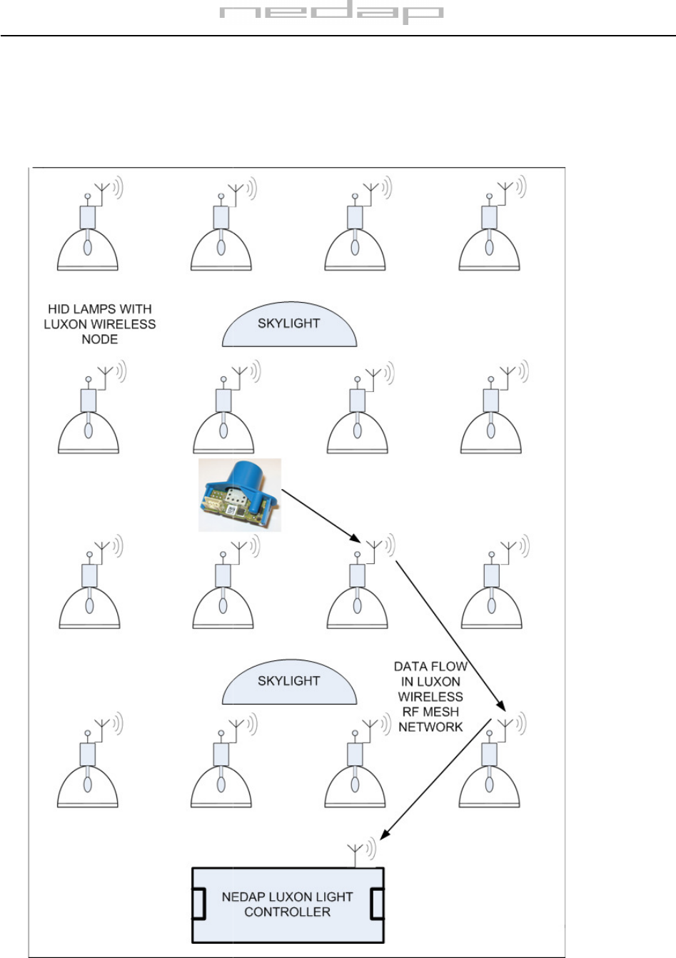
Figure 1. Installation example with
Luxon Wireless
Page 2 of 5
can be added to
a fixture equipped with a Luxon e-
HID ballast. It
communication between the
electronic ballast
and the Luxon Light Controller (LLC).
A
becomes a RF node in the network, and
data can be
the light controller.
Luxon Wireless
HID lamps in a building with skylights
HID ballast. It
facilitates
and the Luxon Light Controller (LLC).
After
data can be
transferred
HID lamps in a building with skylights
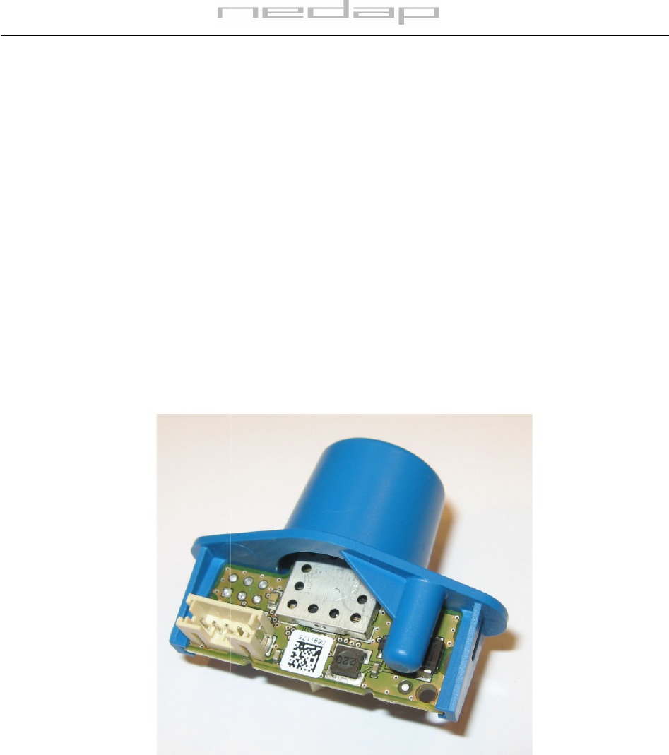
2. Product description
Figure 2: LW245A module
The Luxon Wireless 245A
comes mounted into a protective
module as shown in Figure 2
. This cable is used for both powering the module and the wired
communication with the ballast.
Avoid disconnecting the quite
The black connector is a 4 po
le female connector with polaris
of Luxon e-HID ballasts.
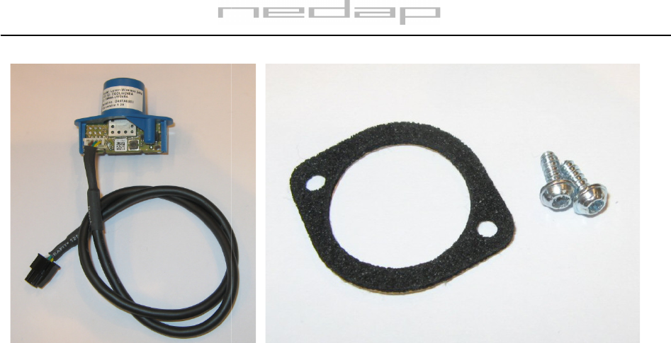
The module comes with 2
3. Warnings
A
lways disconnect the ballast from mains power prior to connecting the Luxon Wireless 245A
After making the connection to the
Luxon
Wireless 245A module carry life voltage.
Sufficient creepage distance must
be kept towards other conductors and enclosure parts.
The enclosure is designed to comply with safety standards.
The Luxon Wireless 245A module may only be installed
4. Mounting
instructions
The Luxon Wireless 245A module must
transceiver have the
best possible unobstructed line of sight to other Luxon Wireless nodes.
For
best performance let the transceiver have a 360 degree field of sight.
The module requires
a 23mm diameter
with
30mm spacing, see also Figure 5
The provided two self tapping sc
rews
The sealing can be used if IP65
ingress
Page 3 of 5
Figure 3: mounting hardware
comes mounted into a protective
plastic enclosure. The
cable
. This cable is used for both powering the module and the wired
Avoid disconnecting the quite
fragile cable connector from the module.
le female connector with polaris
ation and locking, for use with
The module comes with 2
Torx T10 bolts and
a protective sealing, see Fig 3
lways disconnect the ballast from mains power prior to connecting the Luxon Wireless 245A
Luxon
ballast and powering up, the electronic circuits on the Luxon
Wireless 245A module carry life voltage.
It must be made impossible to end us
ers touching the life parts.
be kept towards other conductors and enclosure parts.
The enclosure is designed to comply with safety standards.
The Luxon Wireless 245A module may only be installed
by qualified and trained person
nel
instructions
The Luxon Wireless 245A module must
be mounted to the outside of the luminaire
, to let the RF
best possible unobstructed line of sight to other Luxon Wireless nodes.
best performance let the transceiver have a 360 degree field of sight.
See also the Figure 4.
a 23mm diameter
hole to pop through
, together with two 3mm holes f
30mm spacing, see also Figure 5
. The mounting area shall be flat.
rews
shall be used to secure the module.
ingress
protection is required.
cable
is plugged into the
. This cable is used for both powering the module and the wired
fragile cable connector from the module.
ation and locking, for use with
specific series
a protective sealing, see Fig 3
.
lways disconnect the ballast from mains power prior to connecting the Luxon Wireless 245A
.
ballast and powering up, the electronic circuits on the Luxon
ers touching the life parts.
be kept towards other conductors and enclosure parts.
nel
.
, to let the RF
best possible unobstructed line of sight to other Luxon Wireless nodes.
See also the Figure 4.
, together with two 3mm holes f
or the screws
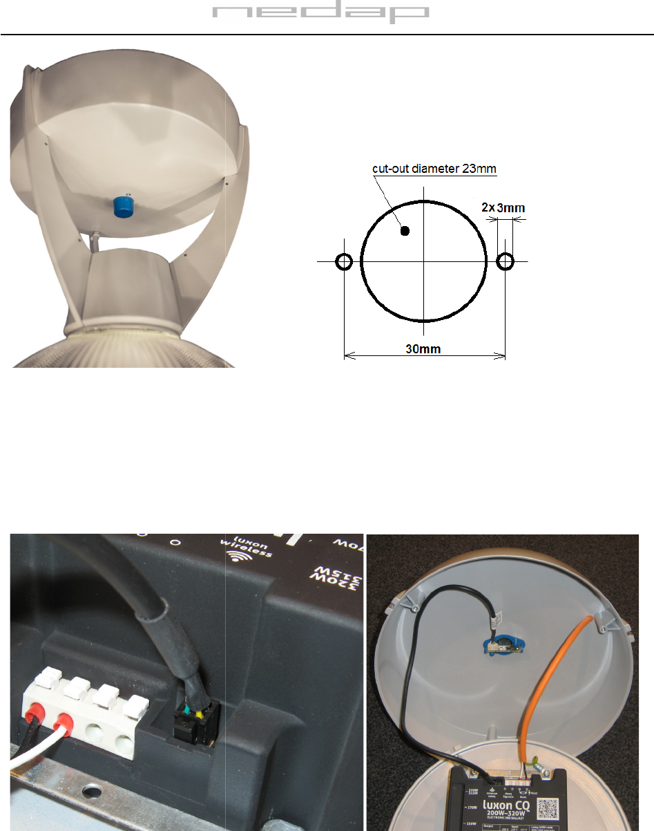
Figure 4: Sample application
5. Connecting
The cable is used to make a connection with the ballast. The
polarization and locking.
Please insert
Note that it might be necessary
to remove a small protection cover
connector.
Please note that the cable
to the ballast
electrical interference.
See also Figure 7.
Figure 6:
connection to ballast (example)
Page 4 of 5
Figure 5: enclosure cut-
out dimensions
The cable is used to make a connection with the ballast. The
black
connector has provisions for both
Please insert
it carefully into the counterpart on the ballast.
See also Figure 6.
to remove a small protection cover
from the ballast that is
to the ballast
shall be kept away from the lamp output
cable to minimize
See also Figure 7.
connection to ballast (example)
Figure 7: example assembly
out dimensions
connector has provisions for both
See also Figure 6.
from the ballast that is
located over the
cable to minimize
Figure 7: example assembly
6. Specifications
7. FCC and IC Declarations
F
CC ID: CGD
Compliance statement
This device complies with part 15 of the FCC Rules and to RSS210 of Industry Canada.
Operation is subject to the following two conditions:
(1) this device may not cause harmful interference, and
(2) this device must accept any interference received, includ
Déclaration Conformité
C
et appareil se conforme aux normes RSS exemptés de
L'opération est soumis aux deu
x conditions suivantes
(1)
cet appareil ne doit causer aucune interférence, et
(2) cet appareil doit accepter n'importe quelle interférence, y inclus interférence qui peut causer une opération non pas
voulu de cet appareil.
Warning
Changes or modifications not expressly approved
authority to operate the equipment.
RF Exposure
To comply with FCC RF exposure requirements for mobile transmitting devices, this transmitter should only be used or
installed at locations
where there is at least 20cm separation distance between the antenna and all persons.
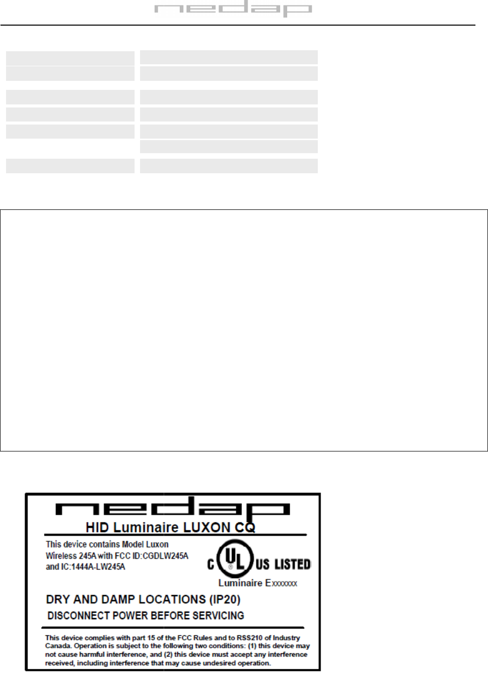
8
. Label artwork example for a fixture with LW245A module
Operating temperature
Safety
EMC
/Telecom
-
40 to
EN60950
EN301489
FCC47 part
Dimensions
50 X 36 mm
Input
Supply
3.3 Vdc, +/
Max. 100mA
Page 5 of 5
CC ID: CGD
LW245A and IC: 1444A-LW245A
This device complies with part 15 of the FCC Rules and to RSS210 of Industry Canada.
Operation is subject to the following two conditions:
(1) this device may not cause harmful interference, and
(2) this device must accept any interference received, includ
ing interference that may cause undesired operation.
et appareil se conforme aux normes RSS exemptés de
licence du Industry Canada.
x conditions suivantes
cet appareil ne doit causer aucune interférence, et
(2) cet appareil doit accepter n'importe quelle interférence, y inclus interférence qui peut causer une opération non pas
Changes or modifications not expressly approved
by the party responsible for compliance could void the user’s
To comply with FCC RF exposure requirements for mobile transmitting devices, this transmitter should only be used or
where there is at least 20cm separation distance between the antenna and all persons.
. Label artwork example for a fixture with LW245A module
40 to
+85
°C
EN60950
EN301489
-1, EN300328 V1.7.1
FCC47 part
15 and IC RSS210
50 X 36 mm
3.3 Vdc, +/
- 5%
Max. 100mA
ing interference that may cause undesired operation.
(2) cet appareil doit accepter n'importe quelle interférence, y inclus interférence qui peut causer une opération non pas
by the party responsible for compliance could void the user’s
To comply with FCC RF exposure requirements for mobile transmitting devices, this transmitter should only be used or
where there is at least 20cm separation distance between the antenna and all persons.