Nedap N V LWIOT1 Luxon IoT Node for wireless control of luminaires operating on 2.45 GHz User Manual
N. V. Nederlandsche Apparatenfabriek NEDAP Luxon IoT Node for wireless control of luminaires operating on 2.45 GHz
UserManual.wiki
>
Nedap N V
>
LWIOT1 User Manual
User Manual
Navigation menu
Upload a User Manual
Namespaces
Wiki Guide
HTML
PDF
Info
Views
User Manual
Discussion / Help
Navigation
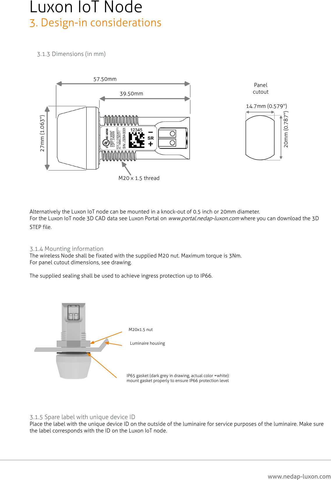
![www.nedap-luxon.comLuxon IoT Node1. General information1.3 Package contentsDescription Units per packagingLuxon IoT Node 12 x 10 pcsM20 Nut 12 x 10 pcsSealing Ring 12 x 10 pcsSpare Label 12 x 10 pcsQuick Install Guide 1Note: Do not remove any labels from the devices. These labels contain important information. The minimum order quantity of the Loxon IoT node MOQ is 10 pcs.1.4 Shipping and storageDescription Packagingdimensions (h x w x d) [mm/inch] Packaging weight [kg/lbs Storage temperatureLuxon IoT Node 245 x 385 x 585 / 9.65 x 15.2 x 23.03.3 / 7.3 20°C to +70°C /-40°F to 158°F- Store the boxes in a dry place1.5 Waste disposal methodsThe local government authority must be consulted for instructions regarding waste processing of the Luxon IoT Node.5](https://usermanual.wiki/Nedap-N-V/LWIOT1/User-Guide-3410384-Page-5.png)