Nedap N V LWIOT1 Luxon IoT Node for wireless control of luminaires operating on 2.45 GHz User Manual
N. V. Nederlandsche Apparatenfabriek NEDAP Luxon IoT Node for wireless control of luminaires operating on 2.45 GHz
User Manual
www.nedap-luxon.com
OEM Design-in Guide
Luxon IoT Node
Version 1.0

www.nedap-luxon.com
Disclaimer
Nedap disclaims all responsibility for any loss, injury, claim, liability or damage of any kind resulting from, arising out of or any way related
to any errors in or omissions from this document and its content, including but not limited to technical inaccuracies and typographical
errors. We do not vouch for the goods being t for the use intended by the purchaser, not even if that use should have been mentioned to
us, unless we have so committed ourselves in writing.
Copyright 2017 © by Nedap N.V.
All rights reserved. No part of this document may be reproduced or distributed in any form or by any means, or stored in a database
retrieval system without the prior express permission of the copyright holder. No part of this book may be reproduced by any means, nor
transmitted, nor translated into a machine language without the written permission of the publisher.
2

www.nedap-luxon.com
Contents OEM Design Guide
1. General information 4
1.1 Introduction 4
1.2 Warnings and instructions 4
1.3 Package contents 5
1.4 Shipping and storage 5
1.5 Waste disposal methods 5
2. Product information 6
2.1 Product range 6
2.2 Accessories 6
2.3 Dimming interface and supply voltage 6
2.3.1 Philips SR interface 6
2.3.2 DALI interface 6
2.3.3 1-10V interface 6
2.4 LED indicator 6
2.5 Luxon IoT node overview 7
2.6 Wiring Diagram 7
2.6.1 SR application 7
2.6.2 DALI application 7
2.6.3 1-10V application 8
2.7 Temperature sensor 8
2.8 Wire specications 8
3. Design-in considerations 9
3.1 Luxon IoT Node 9
3.1.1 Positioning information 9
3.1.2 RF considerations 9
3.1.3 Dimensions (in mm) 10
3.1.4 Mounting information 10
3.1.5 Spare label with unique device ID 10
3.2 Motion sensor applications 11
3.3 Product responsibility 11
4. Luxon Wireless Control Tool 12
5. Luxon Wireless OEM test unit 12
6. Lifetime and reliability 12
7. Possible led drivers 13
8. Specic technical data 14
8.1 Supply voltage 14
8.2 Dim interface 14
8.3 Other specications 14
8.4 Approvals 14
8.5 Compatible light management software 14
9. FCC declarations 15
3

www.nedap-luxon.com
Luxon IoT Node
1. General information
1.1 Introduction
The Luxon IoT Node has been developed by Nedap to accelerate the market adoption of connected lighting. The Luxon IoT
node is be able to control SR, 1-10V and DALI drivers to make LED luminaires IoT-ready and truly sustainable agains low
costs. In addition to wireless control, the IoT node allows for performance monitoring and remote diagnostics of LED xtures
equipped with Philips Xitanium SR drivers and with DALI drivers.
Benets and applications
- Cost-eective solution to create internet
connected and wirelessly controlled luminaires
- Philips Xitanium SR, DALI and 1-10V ready
- Small dimensions
- Easy to integrate, easy to connect
- Supports on/o, dimming and luminaire status
- Temperature sensor integrated
- Lux sensor integrated
- Over the air (OTA) programming of the Luxon IoT Node and Philips Xitanium SR drivers
- Nedap Luxon software features:
- Time, daylight, motion and dim control
- Direct motion sensor control
- Flexible group assigning
- Multi-site management
- Management reports
- Calculated energy logging
1.2 Warnings and instructions
- Read the design guide completely before installing the Luxon IoT Node.
- The Luxon IoT Node may only be installed by qualied and trained personnel.
- No serviceable parts inside, do not open enclosure.
- To avoid possible electrical shock, before installing or servicing the Luxon IoT Node, disconnect the
power by turning o the branch circuit breakers.
- Do not connect mains voltage to the terminals of the Luxon IoT Node.
- Make sure the Luxon IoT Node is operated within the technical limitations of the specication overview in chapter 8.
- The Luxon IoT Node complies with EMC and safety requirements as stated in the specications.
- The Luxon IoT Node provides basic isolation to the control lines. Therefore it is safe to touch the front part of the node.
Note that in case an external sensor is used, its cable and enclosure shall provide sucient isolation to be able to touch it
safely.
- Make sure the IoT node RF antenna is not covered or obstructed by metal for the best RF communication.
4

www.nedap-luxon.com
Luxon IoT Node
1. General information
1.3 Package contents
Description Units per packaging
Luxon IoT Node 12 x 10 pcs
M20 Nut 12 x 10 pcs
Sealing Ring 12 x 10 pcs
Spare Label 12 x 10 pcs
Quick Install Guide 1
Note: Do not remove any labels from the devices. These labels contain important information.
The minimum order quantity of the Loxon IoT node MOQ is 10 pcs.
1.4 Shipping and storage
Description Packaging
dimensions (h x w x d)
[mm/inch]
Packaging weight [kg/lbs Storage temperature
Luxon IoT Node 245 x 385 x 585 /
9.65 x 15.2 x 23.0
3.3 / 7.3 20°C to +70°C /
-40°F to 158°F
- Store the boxes in a dry place
1.5 Waste disposal methods
The local government authority must be consulted for instructions regarding waste processing of the
Luxon IoT Node.
5
www.nedap-luxon.com
Luxon IoT Node
2. Product information
2.1 Product range
Description Part number
Luxon IoT Node 9984976
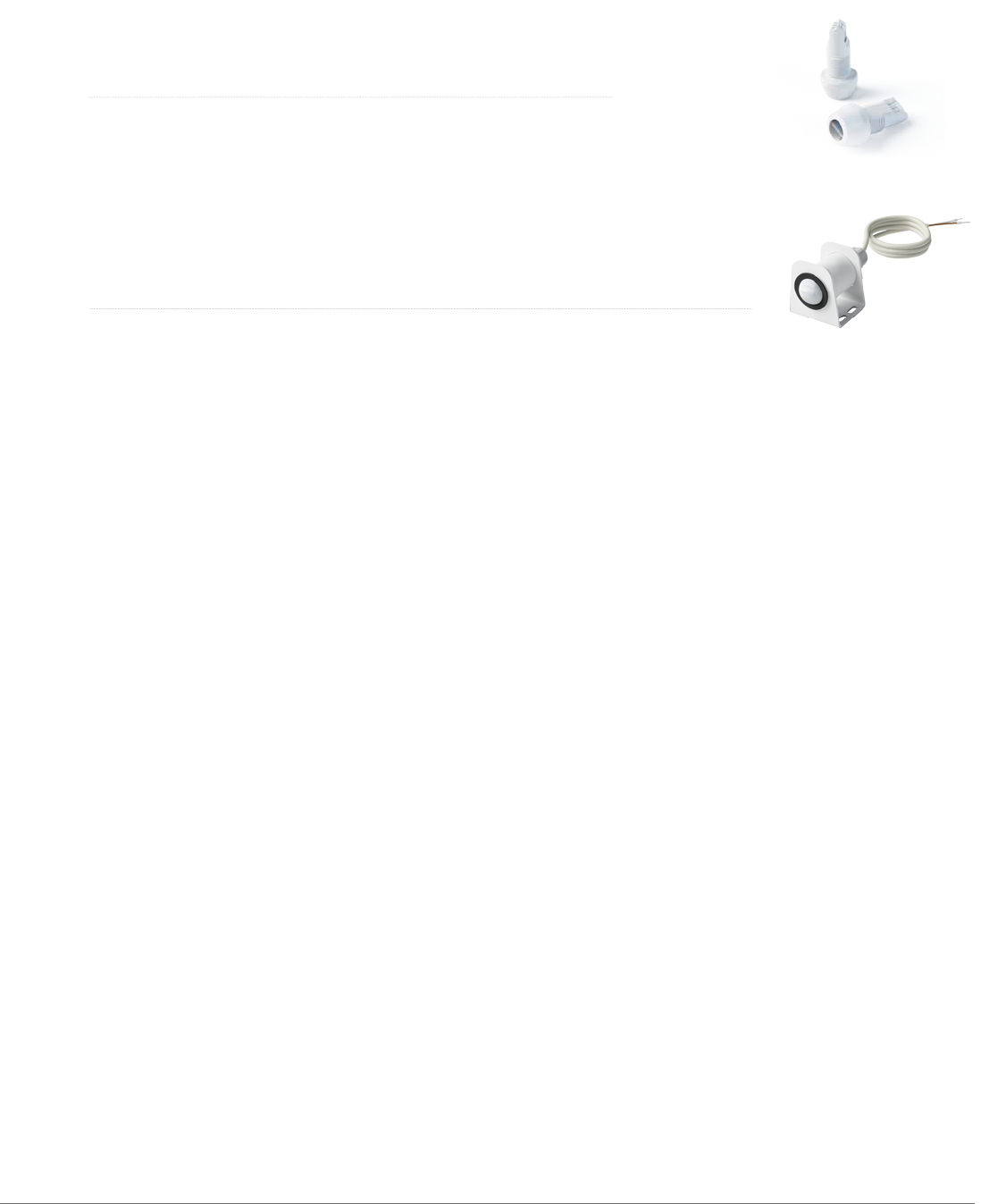
2.2 Accessories
2.3 Dimming interface and supply voltage
The Luxon IoT node determines the interface control mode automatically by measuring supply voltage and dimming
interface voltage. It can be either 1-10V, Philips SR or DALI mode.
2.3.1 Philips SR interface
In Philips SR mode, the Luxon IoT node is powered by the SR driver through the dimming interface.
DALI communication is used to control the SR driver via the same dimming interface. The output is polarity sensitive.
Up to four drivers can be controlled by connecting the dimming ports in parallel.
Note: Each SR driver provides approximately 55mA of current on the DALI bus, and the IoT node sink capability is limited to
250mA. To minimize unnecessary losses, it is recommended to turn on only two DALI power supplies. To turn o the DALI
power supply use the Philips MultiOne congurator.(See Philips website)
2.3.2 DALI interface
In DALI mode, the Luxon IoT node provides DALI bus voltage and communication through the dimming port to drivers with a
DALI control port. The IoT node supply voltage must be 24Vdc.
The output is polarity sensitive although most drivers do not have a polarity sensitive DALI port.
Up to four drivers can be controlled by connecting the dimming ports in parallel.
2.3.3 1-10V interface
In 1-10V mode, the dimming interface transforms the small DC-current from the driver dimming port into a voltage
corresponding to the desired dim level. The IoT node supply voltage must be 12Vdc or 24Vdc.
The dimming voltage range is from 1 to 10V, the output can be set to 0V to switch the LED driver o. (dim to o
functionality)
The output is polarity sensitive. Up to four drivers can be controlled by connecting the dimming ports in parallel.
Description Part number Units per packaging
Luxon Motion Sensor 12m/39ft universal mount 9984526 6 x 1
2.4 LED indicator
Before commisioning (Luxon IoT node not assigned to a Luxon Light Controller):
After powering up the Luxon IoT node, the led indicator lights up green during initialization.
In case of SR/DALI drivers, the led ashes 10 seconds or more during initialization and lights up green continouosly when
nished. In case of 1-10V drivers the led lights up green immediatly.
After commisioning:
The green led will be on for 5 seconds to indicate start-up and then turns o.
The led indicator will start ashing red in case of:
- no driver found due to incorrect wiring or no driver connected
- no control mode (SR, 1-10V or DALI) is detected
6
www.nedap-luxon.com
Luxon IoT Node
2. Product information
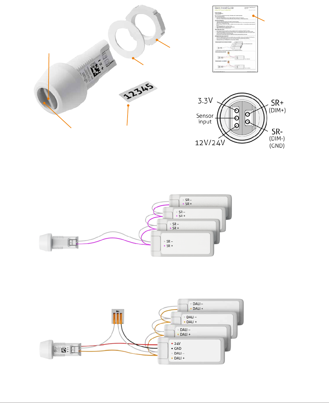
2.5 Luxon IoT node overview
Connections
2.6 Wiring Diagram
See Philips website for the latest information and applicable drivers: http://www.philips.com/xitaniumsr
Up to 4 DALI drivers
Up to 4 Philips Xitanium SR drivers
2.6.2 DALI application
DALI driver requirements:
- One driver needs to supply 24V to the Luxon IoT node; (Power consumption IoT node: 250mW)
LED indicator
M20 Nut
Sealing Ring
Spare Device
ID Label
Quick Install Guide
RF antenna
2.6.1 SR application
7
www.nedap-luxon.com
Luxon IoT Node
2. Product information
2.7 Temperature sensor
The Luxon IoT Node has a temperature sensor, which represents the internal air temperature of the luminaire. This
temperature can be requested in Luxon software to obtain temperature information from the luminaire in which the Luxon
IoT Node is built in. The range of the temperature sensor is -40°C/-40°F to +100°C/+212°F.
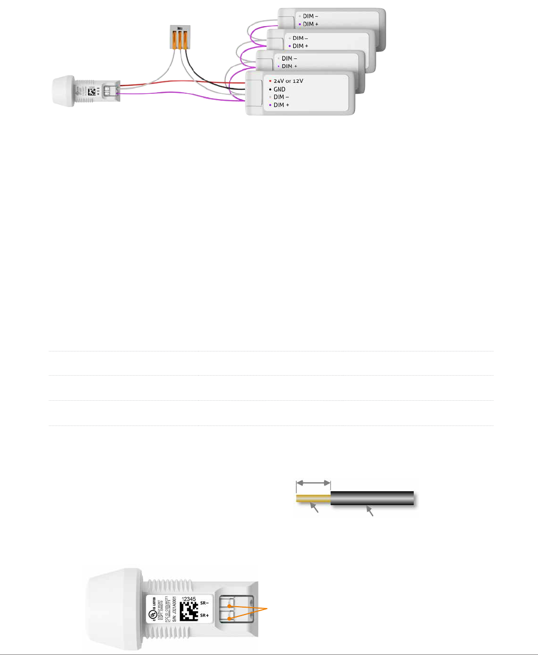
2.8 Wire specications
The Luxon IoT node has 5 connections for use with stranded or solid wires.
See the table below with the applicable wires and information about type and strip length of the wires.
Wire type Wire range Remarks
Solid 0.2 to 0.75 mm2
AWG 24 to 18
Fine stranded 0.2 to 0.75 mm2
AWG 24 to 18
use push button while
inserting wire
Fine stranded with ferrules 0.25 to 0.34 mm2
AWG 24 to 22
Fine stranded tinned 0.25 to 0.5 mm2
AWG 24 to 20
max allowable end diameter
is 1.0 mm
Wire strip length is 8 ± 1mm.
Maximum wire insulation diameter is 2mm.
Use only 1 wire per connector position.
To disconnect a wire push the button while pulling the wire out of the connector contact.
Note: Push the release button right-angled to prevent possible damage to the connector.
Push to release or connect wires
1-10V driver requirements:
- One driver needs to supply 12V or 24V to the Luxon IoT node; (Power consumption IoT node: 250mW)
- All drivers needs to have dim-to-o functionallity.
Note:
For some drivers the control wires have to be considered as basic isolated signals after connecting to the IoT node.
Up to 4 1-10V drivers
2.6.3 1-10V application
insulation
conductor
strip length
8
www.nedap-luxon.com
3.1 Luxon IoT Node
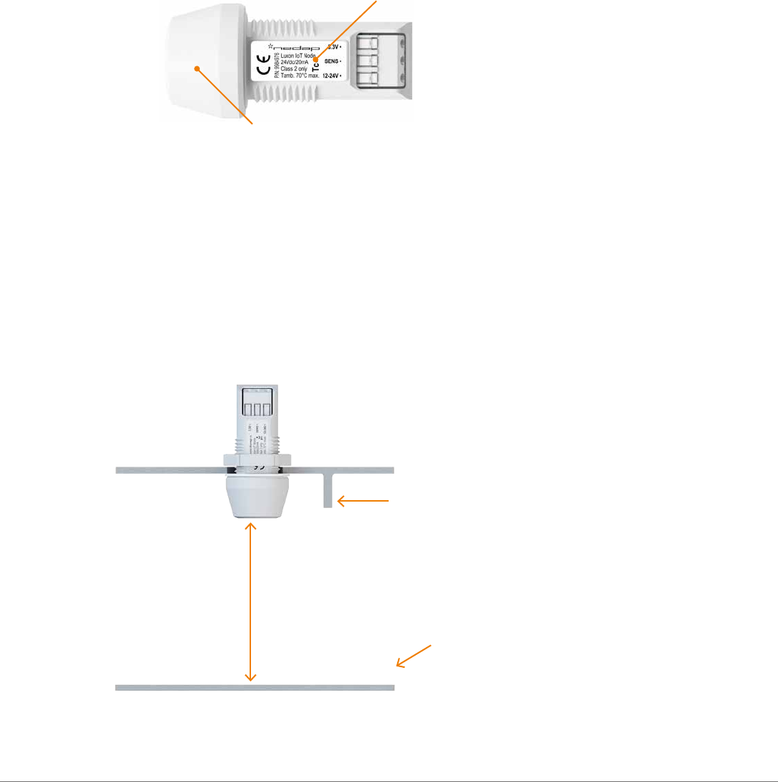
3.1.1 Positioning information
- Keep the Luxon IoT Node away from hot areas to operate below an ambient temperature of +70°C.
- Make sure that the case temperature Tc (see drawing) is always below +75°C or the temperature sensor is always below
80°C. The temperature sensor can be read out by the Luxon wireless control tool, see chapter 4.
3.1.2 RF considerations
- The Luxon IoT Node Node uses wireless communication via an RF antenna located inside the enclosure, see picture.
- In case the Luxon IoT Node is built into a metal enclosure it shall be passed through an opening in the enclosure.
- In case the Luxon IoT Node is built in completely into the luminaire only a plastic enclosure can be used.
Requirements to give the antenna the best possible free 360° communication performance:
- Avoid metal parts close to the antenna.
- Mount the Luxon IoT node pointing downwards or upwards.
- Avoid large horizontal oriented metal parts within 75mm or 3” measured from the center of the antenna.
Luxon IoT Node
3. Design-in considerations
Temperature measuring point Tc
> 75mm
Metal parts close to the antenna will
give a dip in the antenna radiation
pattern.
Metal parts
Antenna
9
www.nedap-luxon.com
Luxon IoT Node
3. Design-in considerations
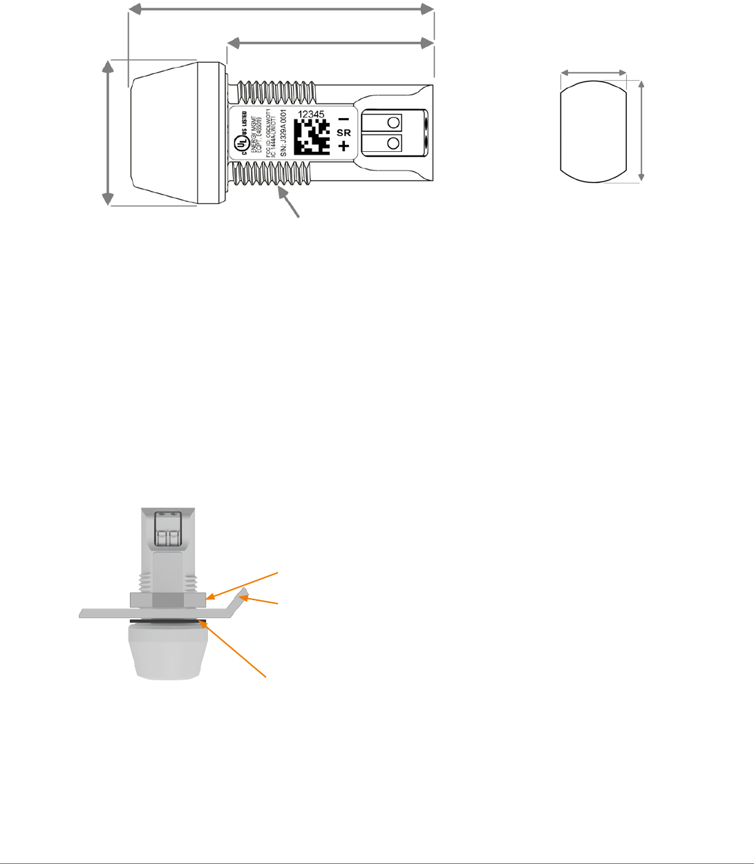
Luminaire housing
M20x1.5 nut
IP65 gasket (dark grey in drawing, actual color =white):
mount gasket properly to ensure IP66 protection level
Panel
cutout
57.50mm
39.50mm
M20 x 1.5 thread
27mm (1.063")
3.1.3 Dimensions (in mm)
Alternatively the Luxon IoT node can be mounted in a knock-out of 0.5 inch or 20mm diameter.
For the Luxon IoT node 3D CAD data see Luxon Portal on
www.portal.nedap-luxon.com
where you can download the 3D
STEP file.
3.1.4 Mounting information
The wireless Node shall be fixated with the supplied M20 nut. Maximum torque is 3Nm.
For panel cutout dimensions, see drawing.
The supplied sealing shall be used to achieve ingress protection up to IP66.
3.1.5 Spare label with unique device ID
Place the label with the unique device ID on the outside of the luminaire for service purposes of the luminaire. Make sure
the label corresponds with the ID on the Luxon IoT node.
14.7mm (0.579")
20mm (0.787")
10
www.nedap-luxon.com
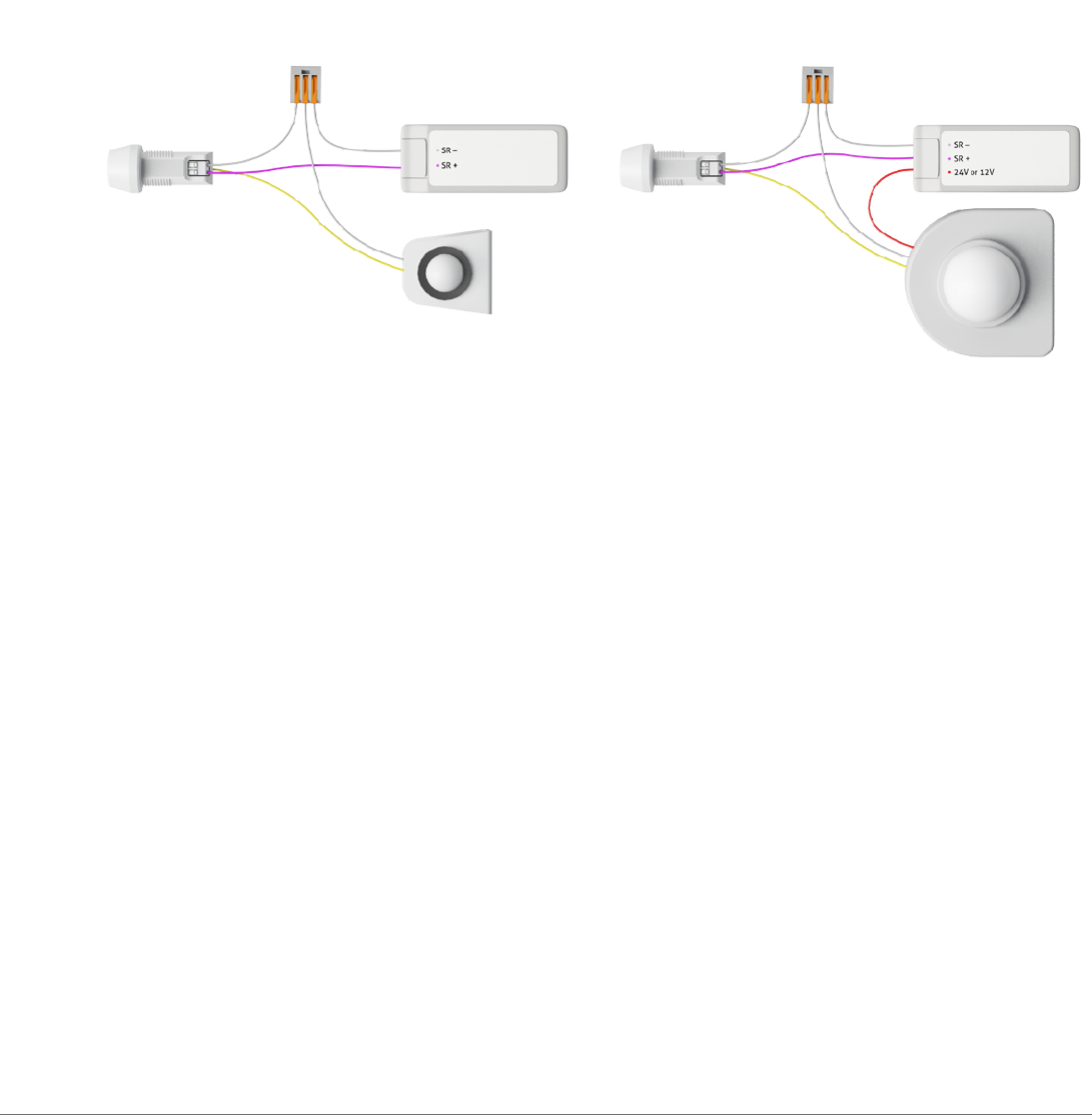
3.2 Motion sensor applications
See the Luxon Motion Sensor Manual for information about mounting the sensor.
The optional Luxon Motion Sensor shall be connected as shows in diagram A by using appropriate wire connectors.
Diagram B shows how to connect third party sensors. Note that third party sensor requires a 12V or 24V external supply
voltage.
For an overview of compatible sensors, please refer to portal.nedap-luxon.com.
The Luxon Motion Sensor cable shall not be lenghtened.
The yellow wire is connected to the sensor input of the Luxon IoT node
3.3 Product responsibility
The Luxon IoT Node is designed to build in. Safe and reliable operation requires that the end-product complies with the
relevant standards and regulations. The end-product shall be designed to adequately protect the Luxon IoT Node from dust,
moisture and pollution.
The manufacturer of the end-product remains responsible for the quality and performance of the build in of the Luxon IoT
Node in compliance with the contents of this OEM Design Guide as well as for the total system in the market. Specifications
of the Luxon IoT Node shall not be exceeded when it is used in the actual operating conditions.
Luxon IoT Node
3. Design-in considerations
A. NEDAP MOTION SENSOR B. 3RD PARTY MOTION SENSOR
11
www.nedap-luxon.com
Luxon IoT Node
4. Luxon Wireless Control Tool
With the Luxon Wireless Control Tool you can test and demonstrate the functionality of your luminaire with the Luxon IoT
node built-in. You can select a luminaire and switch it on and off and dim to a level between 10% and 100%.
You can also retrieve luminaire information about the operation mode (SR, 1-10V or DALI) , temperature, operating hours
and more.
You need a Windows based laptop and Luxon wireless USB key to use this tool. See our partner portal to download the
software and user manual.
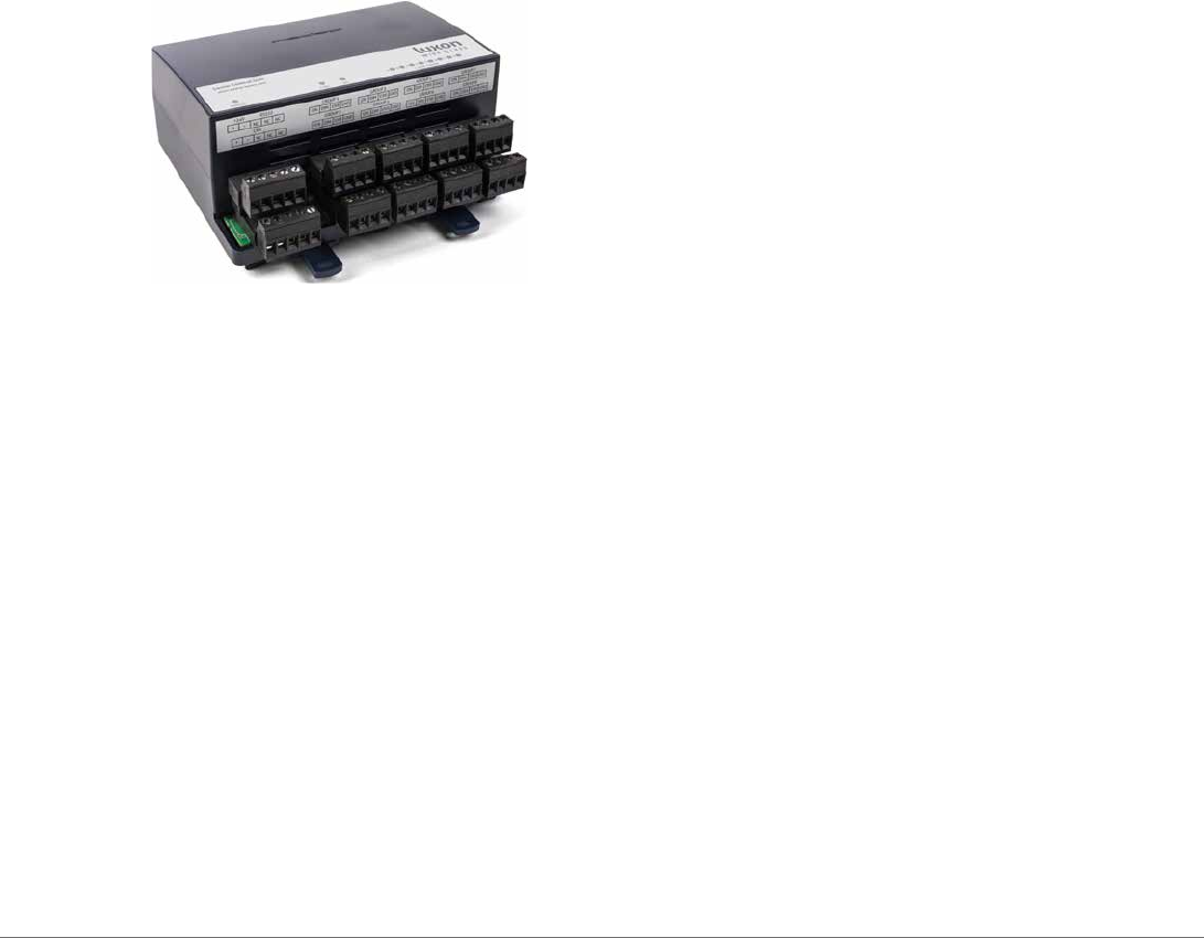
5. Luxon Wireless OEM test unit
With the Luxon Wireless OEM test unit you can check the wireless communication and the correct wiring of the mains and
control wires of the Luxon IoT Node in your production line.
You can control (switch on/off and dim) the luminaire manually by simply connect and operate with two switches.
The control interface can also be connected to your automated production test tool.
You only need this test unit (no laptop or other periferals needed) to control a luminaire.
See the manual delivered together with the test unit how to connect it and control your luminaire.
Ordering information Luxon Wireless OEM test unit: part number: 9984968
6. Lifetime and reliability
The lifetime of the Luxon IoT node in continuous operation over the temperature range of -40°C to +70°C (-40°F to 158°F) is
10 years with a failure rate smaller than 0.2% per year.
12

www.nedap-luxon.com
Luxon IoT Node
7. Possible led drivers
All Philips SR drivers with SR-logo are compatible with the Luxon IoT node.
All IEC 62386 compliant DALI drivers with a 24Vdc auxillary supply shall be compatible with the Luxon IoT node.
All 1-10V drivers which have a 12Vdc or 24Vdc auxillary supply and dim-to-off functionality (see required theshold level in
the specification) shall be compatible with the Luxon IoT node.
For all possible drivers see Luxon Portal: www.portal.nedap-luxon.com
13

www.nedap-luxon.com
8.5 Compatible light management software
Software Version
Floorplanner 4.7 or higher
Luxon Light Controller (LLC) 2.13 or higher
Server 3.1 or higher
Update your software in case the version is lower than indicated above. Contact Nedap customer support if you need
assistance: support@nedap-luxon.com
Luxon IoT Node
8. Specic technical data
8.1 Supply voltage
SR mode powered by SR interface
1-10V mode 12Vdc ±10% or 24Vdc ±10%
DALI mode 24Vdc±10%
8.3 Other specications
8.2 Dim interface
RF frequency 2.45GHz
RF range 40m / 131ft.
Operating ambient Node -40°C to +70°C / -40°F to +158°F
Maximum Tcase Node 75°C / 167°F
Storage temperature -20°C to +70°C / -4°F to 158°F
Lifetime 10 years
Failure rate < 0.2% / year
Ingress Protection IP66
Weight 16.5g / 0.58oz
Power Usage Node <250mW
Motion Sensor Input Compatible with Luxon Motion Sensor 12m
Lux sensor range 10 to 1500 lux
Temperature sensor range -40°C to +100°C / -40°F to 212°F
Connector Push-in terminals, see chapter 2.8 for wire specications
Dimensions DxH 27.0 x 57.5mm / 1.06 x 2.64 inch
SR interface Philips SR compatible
up to 4 drivers
1-10V interface Compatible with IEC 60929 drivers
8mA max sink current
Dim-to-o Threshold : 0.3V
Required aux supply: 12Vdc±10% or 24Vdc±10%
DALI interface Compatible with DALI drivers
DALI power supply integrated: 8mA / up to 4 drivers
Require aux supply: 24Vdc±10%
8.4 Approvals
EMC Safety
CE, RTTE, FCC CE, UL-listed
14

www.nedap-luxon.com
This device complies with part 15 of the FCC Rules and with Industry Canada’s licence-exempt RSSs. Operation is subject
to the following two conditions:
(1) This device may not cause interference; and
(2) This device must accept any interference, including interference that may cause undesired operation of the device.
Warning (15.21)
Changes or modications not expressly approved by the party responsible for compliance could void the user’s authority
to operate the equipment.
Cet appareil se conforme aux normes RSS exemptés de license du Industry Canada. L’opération est soumis aux deux
conditions suivantes:
(1) cet appareil ne doit causer aucune interférence, et
(2) cet appareil doit accepter n’importe quelle interférence, y inclus interférence qui peut causer une opération non pas
voulu de cet appareil.
Les changements ou modications n’ayant pas été expressément approuvés par la partie responsable de la conformité
peuvent faire perdre à l’utilisateur l’autorisation de faire fonctionner le matériel.
FCC and ISED Radiation Exposure Statement
This equipment complies with FCC (OET Bulletin 65) and Canadian radiation exposure limits set forth in RSS-102 for a
uncontrolled environment. This equipment should be installed and operated with a minimum distance of 20 cm between
the radiator and your body. This transmitter must not be co-located or operating in conjunction with any other antenna or
transmitter.
Cet équipement est conforme a RSS-102 limites énoncées pour un environnement non contrôlé. Cet équipement doit être
installé et utilisé avec une distance minimale de 20 cm entre le radiateur et votre corps.
ISED EMC Declaration
This Class B digital apparatus complies with Canadian ICES-003.
Cet appareil numérique de Classe B est conforme à la norme Canadienne ICES-003.
FCC Information to the user (15.105(b))
Note: This equipment has been tested and found to comply with the limits for a class B digital devices, pursuant to part 15
of the FCC Rules. These limits are designed to provide reasonable protection against harmful interference in a residential
installation. This equipment generates, uses and can radiate radio frequent energy and, if not installed and used in
accordance with the instructions, may cause harmful interference to radio communications.
However, there is no guarantee that interference will not occur in a particular installation. If this equipment does not cause
harmful interference to radio or television reception, which can be determine by turning the equipment o and on, the
user is encouraged to try to correct the interference by one or more of the following measures:
• Reorient or relocate the receiving antenna.
• Increase the separation between the equipment and receiver.
• Connect the equipment into an outlet on a circuit dierent from that to which the receiver.
• Any changes or modications not expressly approved by the party responsible for compliance could void the
user's authority to operate the equipment.
• To ensure compliance with FCC regulations, use only the shielded interface cables provided with the product, or
additional specied components or accessories that can be used with the installation of the product
Luxon IoT Node
9. FCC declarations
15
Subject to change without notice (RH20170406)
www.nedap-luxon.com
Nedap N.V. | Parallelweg 2 | 7141 DC Groenlo| The Netherlands
T +31 (0)544 471 111 | info@nedap-luxon.com | www.nedap-luxon.com
Nedap Inc. | 401 Edgewater Place, Suite 560 | Wakefield , MA 01880 USA
T + 1 844.876.3327 | info@nedap-luxon.com | www.nedap-luxon.com