Nedap N V MACESMART Reader for 13.56 MHz NFC cards and also BT User Manual 267006X
N. V. Nederlandsche Apparatenfabriek NEDAP Reader for 13.56 MHz NFC cards and also BT 267006X
UserManual.wiki
>
Nedap N V
>
MACESMART User Manual
User Manual
Navigation menu
Upload a User Manual
Namespaces
Wiki Guide
HTML
PDF
Info
Views
User Manual
Discussion / Help
Navigation
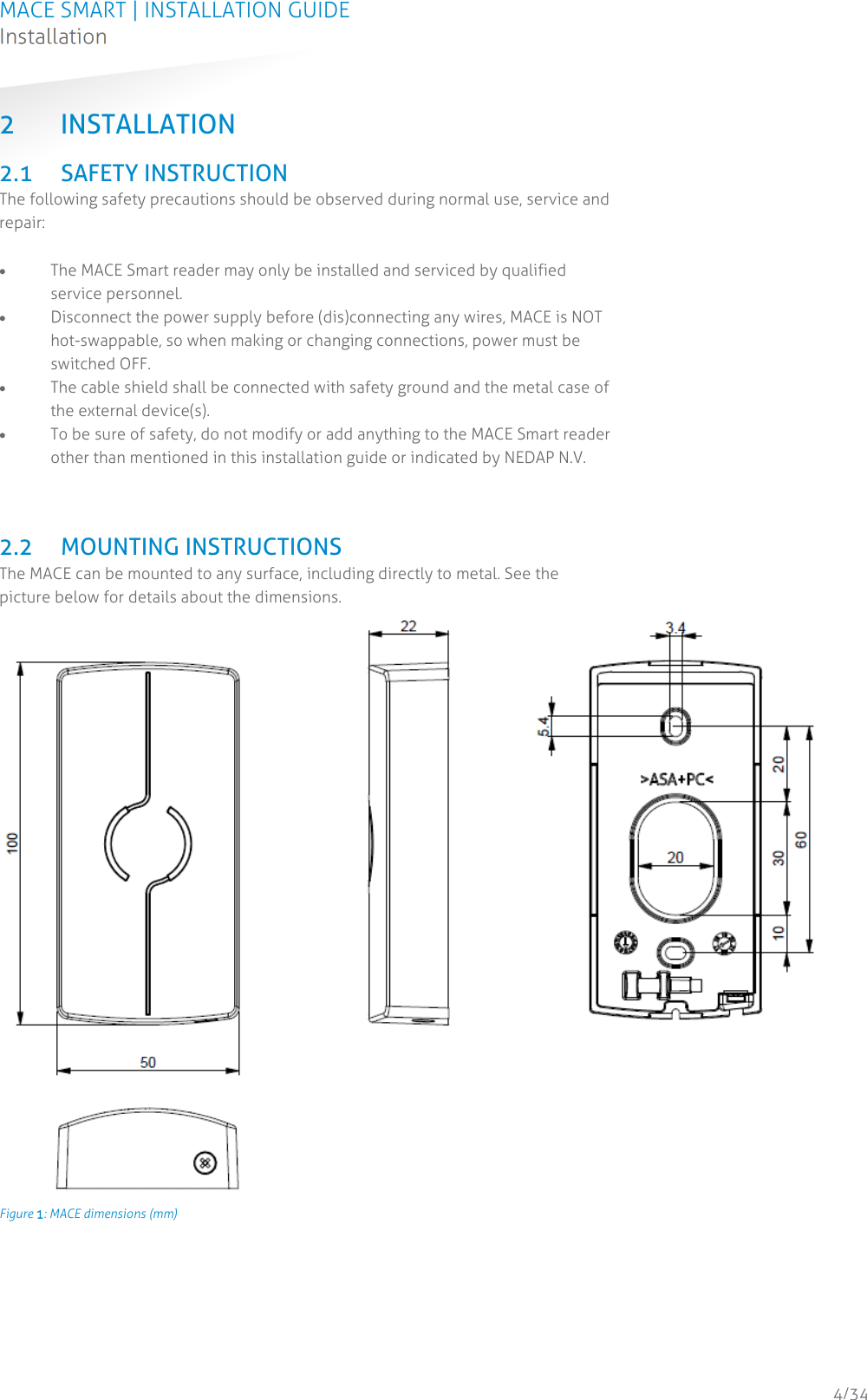
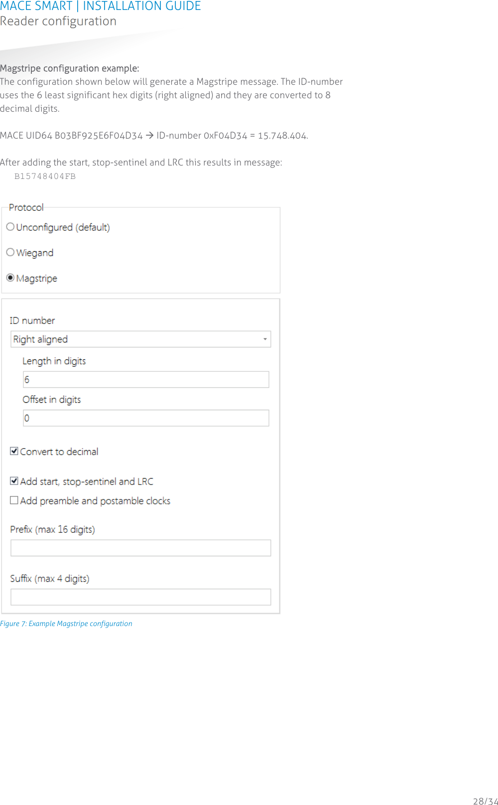
![MACE SMART | INSTALLATION GUIDE Technical Specifications 30/34 A TECHNICAL SPECIFICATIONS Technical information MACE Smart Operating frequency Bluetooth Low Energy 2.402 – 2.480 GHz NFC & smartcards: 13.56 MHz Dimensions 100 x 50 x 22 mm [ 3.9 x 2 x 0.9 inch ] Weight 75 g [ 0.17 lbs ] Housing Polycarbonate Color RAL7016 Protection IP65 [ approx.NEMA4x ] Detection range Bluetooth Low Energy: configurable up to 25cm (proximity), 2m (short), 5m (medium) or 15m (long). NFC and smartcards: up to 5cm. Supported RFID cards ISO14443-3A, Mifare DESFire (EV1), Mifare Classic, Mifare Ultralight, Mifare Plus (SL3) ISO15693, HID iCLASS (UID only), MACE Card Operating temperature -30...+60°C (-22...+140°F) Power 12 … 24 VDC (from power-limited UL294 or UL603 Listed power source) Current consumption 0.2A@12VDC, 0.1A@24VDC Input 2 TTL digital inputs for LED control (RED/GREEN) 1 TTL digital input for beeper control Tamper indication Yes, magnetic tamper switch Cable length Wiegand 150 m [ 500 ft. ] 22AWG RS485 1200 m [ 3950 ft. ] when installed properly Interfaces RS485 interface. Please consult your representative for additional interfacing options. Output Wiegand, Magstripe (clock & data) Compliance Europe RE Directive 2014/53/EU USA: FCC Title 47 Part 15B and 15C Canada: ISED ICES-003 and RSS210 Certifications Safety: EN60950-1 EMC: EN301489 Telecom: EN330 330 and EN300 328 Human Exposure assessment: ICNIRP Guidelines, EN62369 and EN50364 UL294 UL UL294 6th ed. – outdoor usage](https://usermanual.wiki/Nedap-N-V/MACESMART/User-Guide-3869980-Page-30.png)