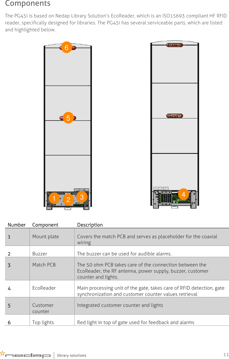
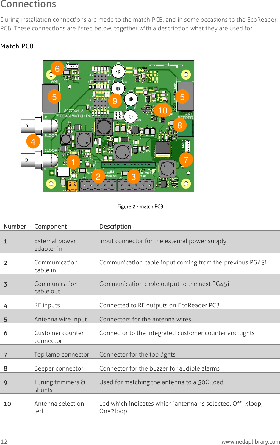
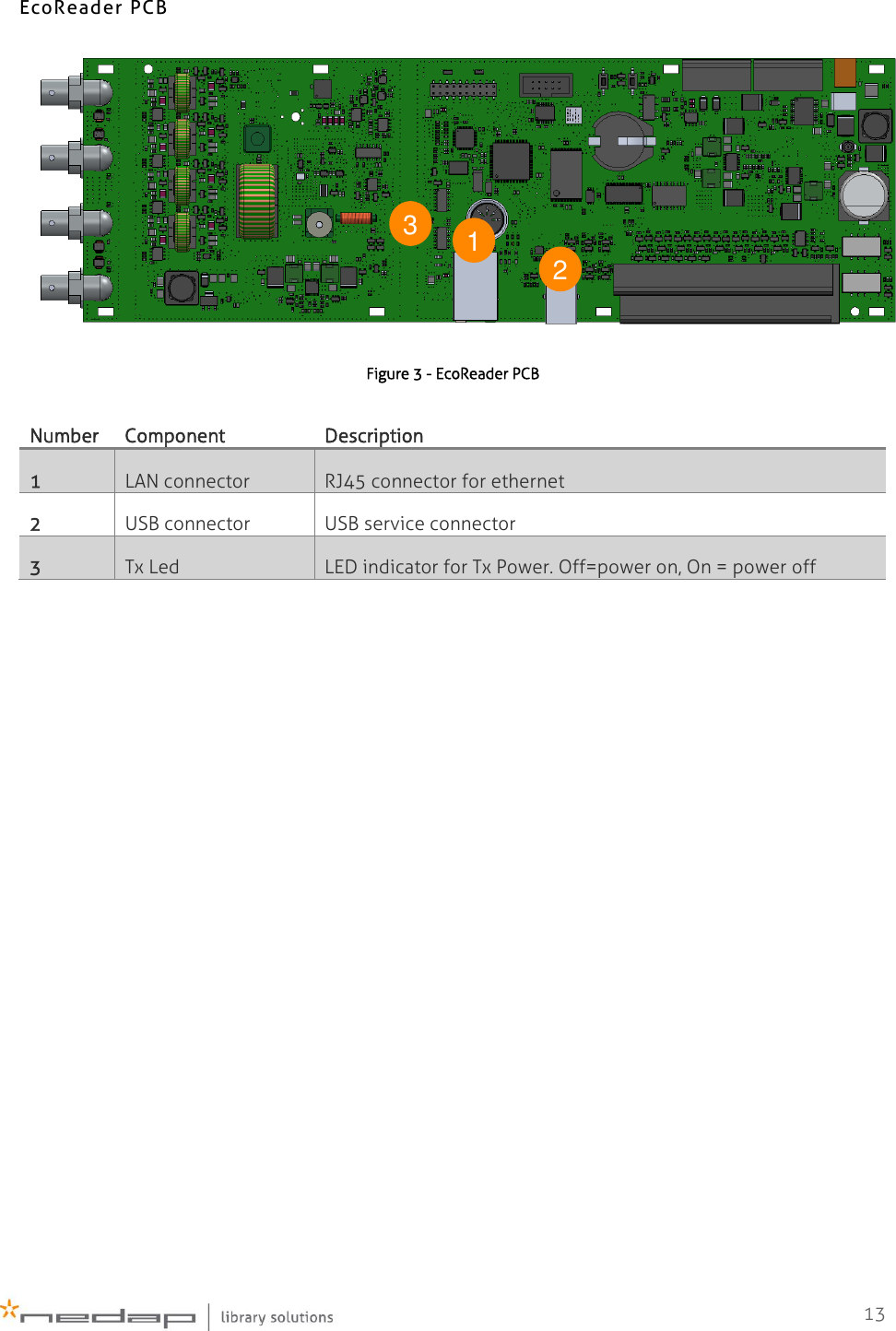
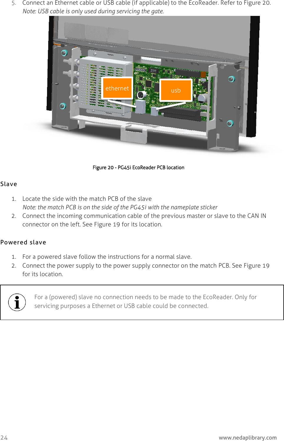
Nedap N V PG45I135 Inductive RFID Card Reader operating on 13.56 MHz User Manual Installation Guide
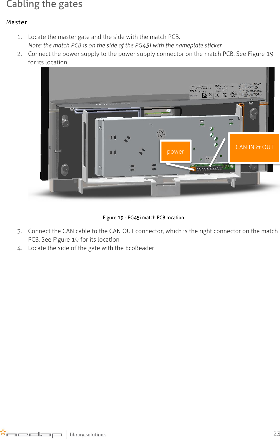
N. V. Nederlandsche Apparatenfabriek NEDAP Inductive RFID Card Reader operating on 13.56 MHz Installation Guide
UserManual.wiki
>
Nedap N V
>
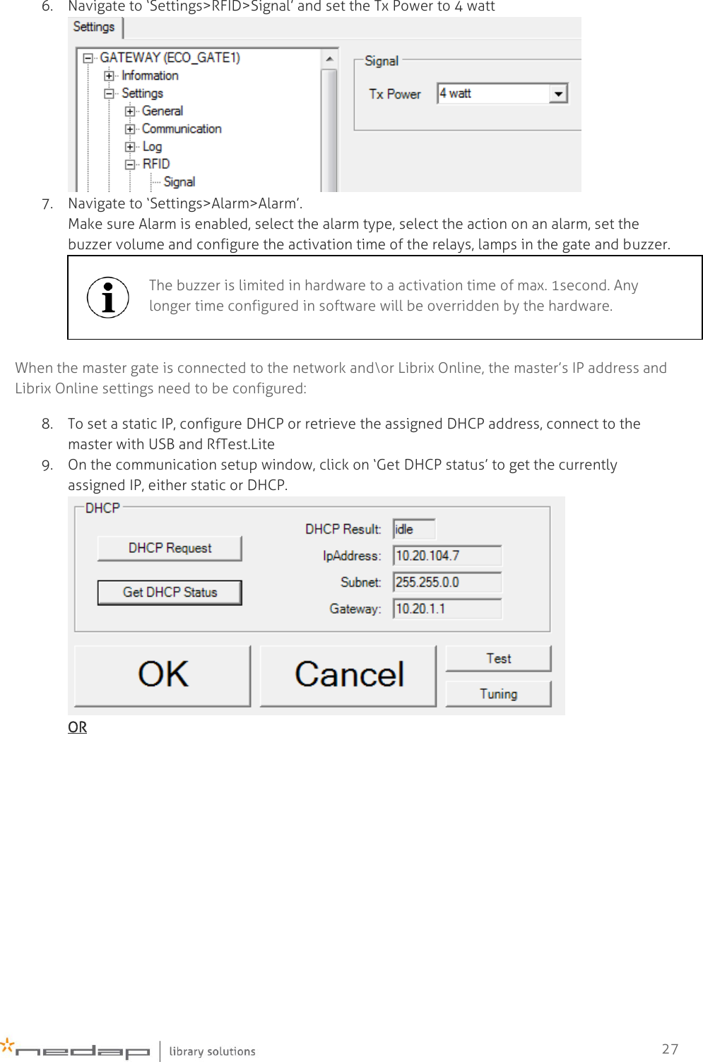
PG45I135 User Manual
Users manual
Navigation menu
Upload a User Manual
Namespaces
Wiki Guide
HTML
PDF
Info
Views
User Manual
Discussion / Help
Navigation