Nedap N V PG45I135 Inductive RFID Card Reader operating on 13.56 MHz User Manual Installation Guide
N. V. Nederlandsche Apparatenfabriek NEDAP Inductive RFID Card Reader operating on 13.56 MHz Installation Guide
Users manual
Installation Guide
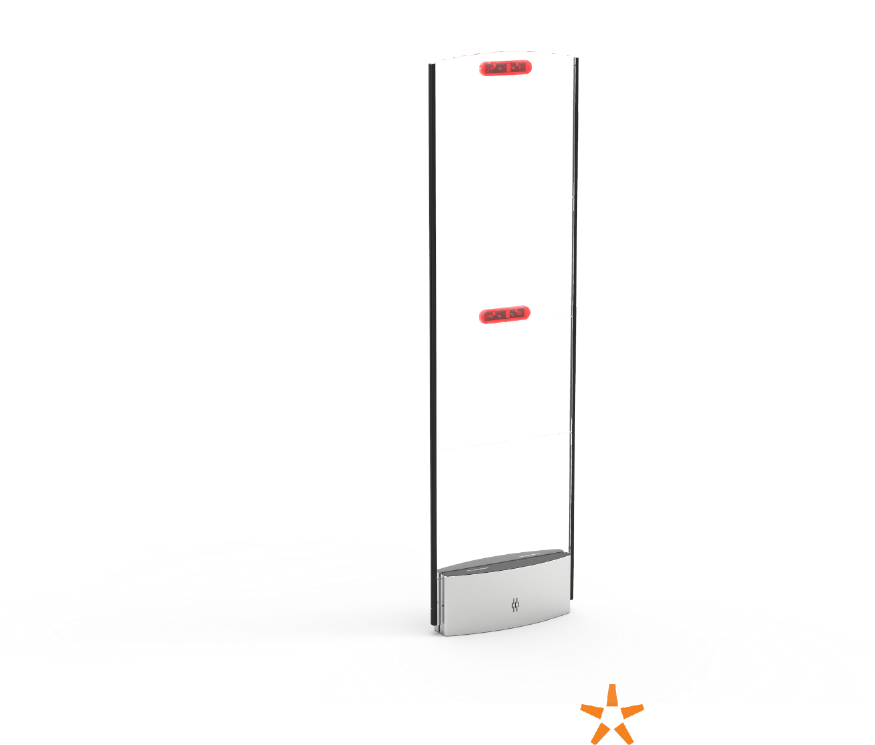
PG45i Detection Gate (9984232)
Your library’s collection is a valued community investment. To protect these library resources you
can use the PG45i Library Detection Gates. The gates help you protect your printed materials and
digital media from unintended removal or theft. When someone walks through the gates with a
library item that is not checked out properly an alarm will sound.
Version: 1.13
published on Thursday, February 09, 2017

2 www.nedaplibrary.com
Table of Contents
Table of Contents ................................................................................................................................................................................... 2
Technical support .................................................................................................................................................................................. 4
Document history .................................................................................................................................................................................. 5
Safety Precaution ................................................................................................................................................................................... 6
WARNING ................................................................................................................................................................................................... 7
Declaration of Conformity................................................................................................................................................................. 7
EU .............................................................................................................................................................................................................. 7
FCC and IC ............................................................................................................................................................................................. 7
Product overview ................................................................................................................................................................................... 9
Content of Box .................................................................................................................................................................................... 9
Power supply specifications ....................................................................................................................................................... 9
Accessories ........................................................................................................................................................................................... 9
Dimensions ........................................................................................................................................................................................ 10
Components...................................................................................................................................................................................... 11
Connections ...................................................................................................................................................................................... 12
Installation .............................................................................................................................................................................................. 14
Preparing ............................................................................................................................................................................................ 14
System overview ............................................................................................................................................................................ 15
Customer counting overview................................................................................................................................................... 16
Testing the customer counting direction .......................................................................................................................... 20
Mounting the gates ....................................................................................................................................................................... 21
Cabling the gates ........................................................................................................................................................................... 23
Settings configuration ...................................................................................................................................................................... 25
System operation ................................................................................................................................................................................ 29
APPENDIX A. ........................................................................................................................................................................................... 30
Frequently Asked Questions ......................................................................................................................................................... 31

3

4 www.nedaplibrary.com
Technical support
Email address
support-library@nedap.com
Visitors address
Nedap Library Solutions
Parallelweg 2d
Groenlo
The Netherlands
Postal address
Nedap Library Solutions
P.O. box 102
7140 AC Groenlo
The Netherlands
Telephone Number
Tel: +31(0)85 8888850
©2016 Nedap Library Solutions
The software / hardware described in this document / file is furnished under a license agreement and may be used
only in accordance with the terms of agreement.
Documentation copyright notice
Any technical documentation that is made available by Nedap Library Solutions is the copyrighted work of Nedap
Library Solutions and is owned by Nedap Library Solutions.
Disclaimer
NO WARRANTY. The technical documentation is being delivered to you and Nedap Library Solutions makes no
warranty as to its accuracy or use. Any use of the technical documentation or the information contained herein is
at the risk of the user. Documentation may include technical or other inaccuracies or typographical errors. Nedap
Library Solutions has the right to make changes without prior notice. No part of this publication may be copied
without the express written permission of Nedap Library Solutions, Parallelweg 2d, 7141 DC Groenlo, The
Netherlands.
Trademarks
Nedap, and the Nedap logo are registered trademarks of Nedap N.V. Groenlo. Other product names mentioned in
this manual may be trademarks or registered trademarks of their respective companies and are hereby
acknowledged. Printed in the Netherlands.

5
Document history
Version
Date
Author
Description
1.0
12-05-2016
G. Heinen
First version of this document
1.1
12-05-2016
G. Heinen
Replaced picture on front page
1.2
24-05-2016
G. Heinen
Fixed typos
1.3
24-05-2016
R. Heersink
Completed marketing check and released for publication
1.5
24-05-2016
E. Veurman
Edited document properties and system links
1.6
04-07-2016
E. Veurman
Updated images and mounting instructions (nuts and
bolts)
1.7
18-10-2016
E. Veurman
Temporarily changed spec # gates powered by one power
supply to 3 gates until further notice.
1.8
9-2-2017
E. Veurman
Added accessories for Conformance.

6 www.nedaplibrary.com
Safety Precaution
For indoor use only
Installation of these products should be performed by a qualified installation partner.
Do not use the product in damp places.
If you smell smoke or other odors or hear a strange sound, unplug the power cord and
contact your dealer.
Protect the cables from physical or mechanical abuse, such as being twisted, kinked,
pinched, closed in a door, or walked upon. Pay particular attention to plugs, wall outlets,
and the point where the cord exits the product.
Do not disassemble, repair or modify the product at your own discretion.
To reduce the risk of electrical shock or damage, do not expose this device to rain or
moisture.
Refer all servicing to qualified service personnel. Servicing is required when the system
has been damaged in any way, such as the power supply cord or plug is damaged, liquid
has been spilled, or the device has been dropped.
Use only UL listed mounting material, which complies with local regulations.
This product is intended to be supplied by a UL Listed Power Unit marked “Class 2” or
“LPS” or “Limited Power Source” with output rated for 24 VDC, 60W.
Do not connect directly to mains power for any reason.
Do not install near any heat sources such as radiators, heat registers, stoves, or other
sources of heat.
Do not use strong or abrasive detergents when cleaning the device body.
WARNING: Do not place near electromagnetic fields.

7
WARNING
This equipment should be installed, operated, serviced, and repaired by qualified personnel only.
The installation and interconnection of this equipment to facility wiring and other equipment must
be done by a competent, qualified craftsperson who is familiar with applicable standards and codes
governing the installation. Installation methods, practices, or procedures that are unauthorized or
done improperly are dangerous and could result in serious personal injury or damage to property
and equipment.
Declaration of Conformity
EU
Hereby, De N.V. Nederlandsche Apparatenfabriek "Nedap" declares that the radio equipment type
PG45i is in compliance with Directive 1999/5/EC. The full text of the EU declaration of conformity is
available at the following internet address: http://www.nedaplibrary.com (login required).
FCC and IC
FCC-ID: CGDPG45I135 IC: 1444A-PG45I135
This equipment has been tested and found to comply with the limits for a Class B digital device,
pursuant to part 15 of the FCC Rules. These limits are designed to provide reasonable protection
against harmful interference in a residential installation. This equipment generates, uses and can
radiate radio frequency energy and, if not installed and used in accordance with the instructions, may
cause harmful interference to radio communications. However, there is no guarantee that
interference will not occur in a particular installation. If this equipment does cause harmful
interference to radio or television reception, which can be determined by turning the equipment off
and on, the user is encouraged to try to correct the interference by one or more of the following
measures:
- Reorient or relocate the receiving antenna.
- Increase the separation between the equipment and receiver.
- Connect the equipment into an outlet on a circuit different from that to which the receiver is
connected.
- Consult the dealer or an experienced radio/TV technician for help
This device complies with part 15 of the FCC Rules. Operation is subject to the following two
conditions:
(1) This device may not cause harmful interference, and
(2) This device must accept any interference received, including interference that may cause
undesired operation.
Changes or modifications not expressly approved by the party responsible for compliance could void
the user’s authority to operate the equipment.
Cet appareil se conforme aux normes CNR210 exemptés de license du Industry Canada. L’opération
est soumis aux deux conditions suivantes:
(1) Cet appareil ne doit pas causer interférence et

8 www.nedaplibrary.com
(2) Cet appareil doit accepter toute interférence, y compris l'interférences qui peuvent causer un
mauvais fonctionnement de l'appareil.
Les changements ou modifications n’ayant pas été expressément approuvés par la partie
responsable de la conformité peuvent faire perdre à l’utilisateur l’autorisation de faire fonctionner le
matériel.
This equipment complies with FCC and Canadian radiation exposure limits set forth for an
uncontrolled environment. This equipment should be installed and operated with a minimum
distance of 20 cm between the radiator and your body. This transmitter must not be co-located or
operating in conjunction with any other antenna or transmitter.
Cet équipement est conforme a CNR102 limites énoncées pour un environne- ment non contrôlé.
Cet équipement doit être installé et utilisé avec une distance minimale de 20 cm entre le radiateur et
votre corps.
This Class B digital apparatus complies with Canadian ICES-3.
Cet appareil numérique de Classe B est conforme à la norme Canadienne NMB-3.
9
Product overview
Content of Box
When you receive the box, it is strongly advised to check the contents of the box before installation.
The box should contain the following components:
Quantity
Article number
Article name
Comments
1x
9984232
PG45i detection gate
1x
8025622
Power & communication
cable
(two ferrites and connectors included)
1x
5410487
Floor mounting plate
installation template and spacer for
use with floor threshold
* note that no power supply is supplied with the gates
Power supply specifications
A power supply with the following specifications should be used together with a system consisting of
PG45i gates:
- Output voltage: 24V DC
- Minimum output current: 2,5A
(note: max. 3x PG45i gates can be daisy-chained on one power supply, regardless of power
supply capabilities)
- Minimum output power: 60W
- Class2, LPS or ’Limited Power Supply’ rating
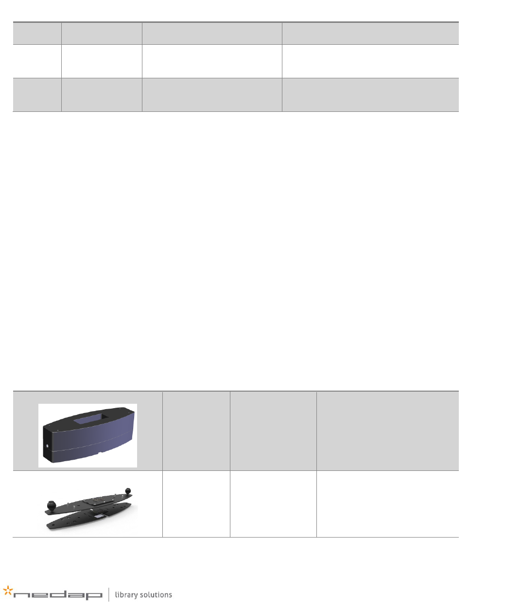
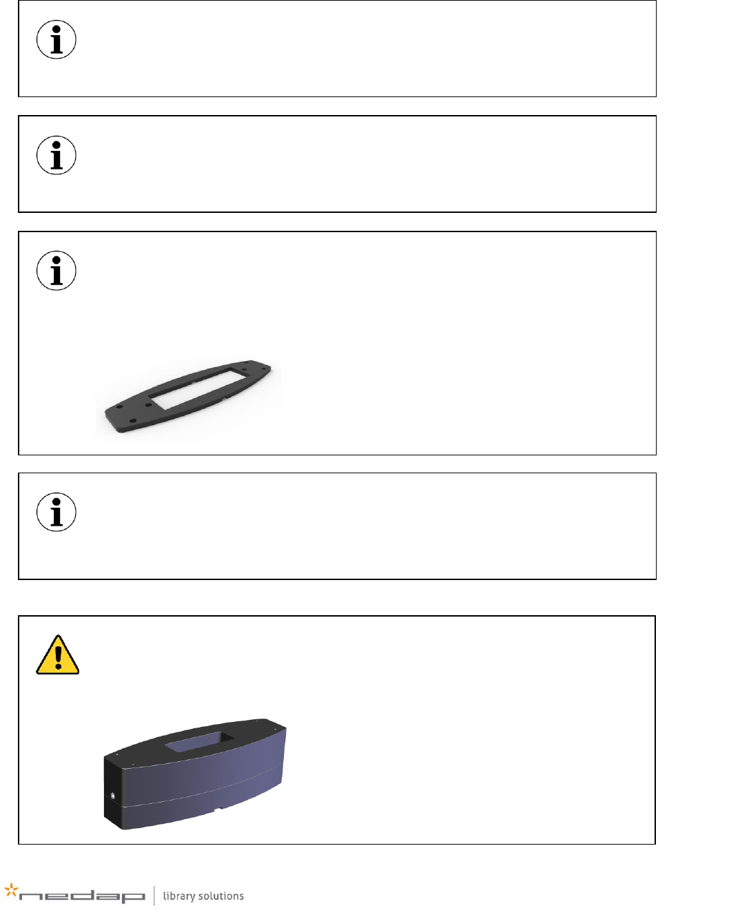
Accessories
The PG45i has some optional accessories. They are listed in the table below, with their Nedap article
numbers, which you can use to order the accessories.
Photo
Article
number
Article name
Comments
7603282
Plastic Foot Raise
It heightens the gate to a total
of 1,80m (71”).
Required for installations
where FCC and IC are
applicable.
9984844
Docking Station
Connector plates to make the
PG45i easily detachable.
10 www.nedaplibrary.com
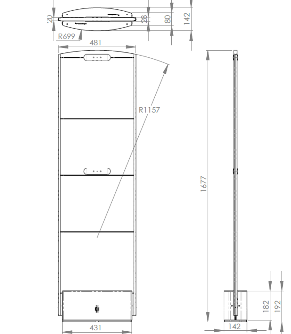
Dimensions
Figure 1 - PG45i gate dimensions
*all dimensions are in mm
11
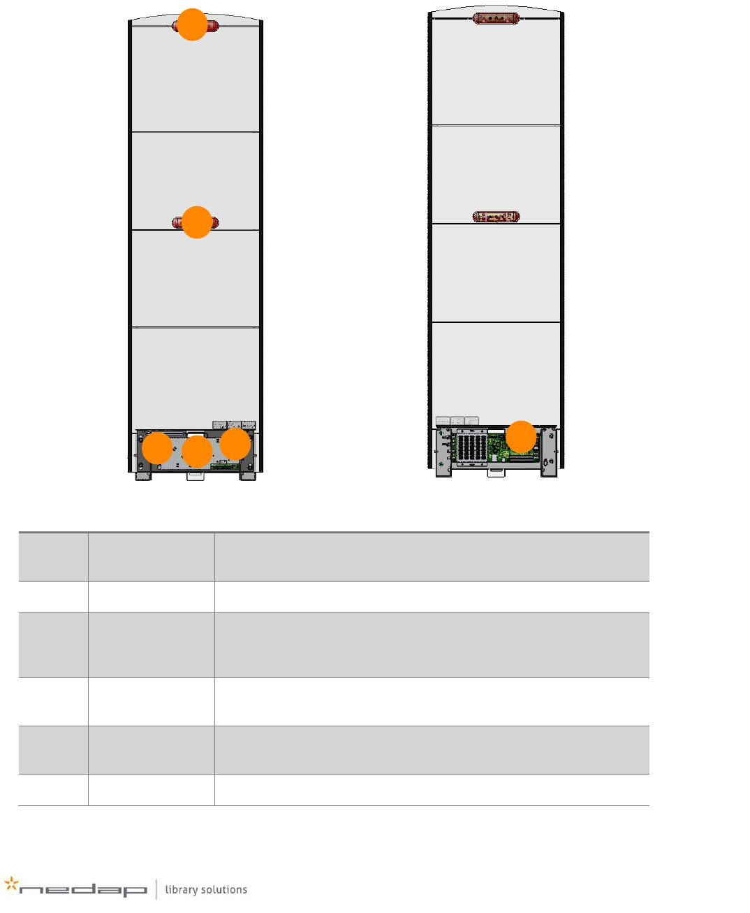
Components
The PG45i is based on Nedap Library Solution’s EcoReader, which is an ISO15693 compliant HF RFID
reader, specifically designed for libraries. The PG45i has several serviceable parts, which are listed
and highlighted below.
Number
Component
Description
1
Mount plate
Covers the match PCB and serves as placeholder for the coaxial
wiring
2
Buzzer
The buzzer can be used for audible alarms.
3
Match PCB
The 50 ohm PCB takes care of the connection between the
EcoReader, the RF antenna, power supply, buzzer, customer
counter and lights.
4
EcoReader
Main processing unit of the gate, takes care of RFID detection, gate
synchronization and customer counter values retrieval
5
Customer
counter
Integrated customer counter and lights
6
Top lights
Red light in top of gate used for feedback and alarms
1
2
3
4
5
6
12 www.nedaplibrary.com
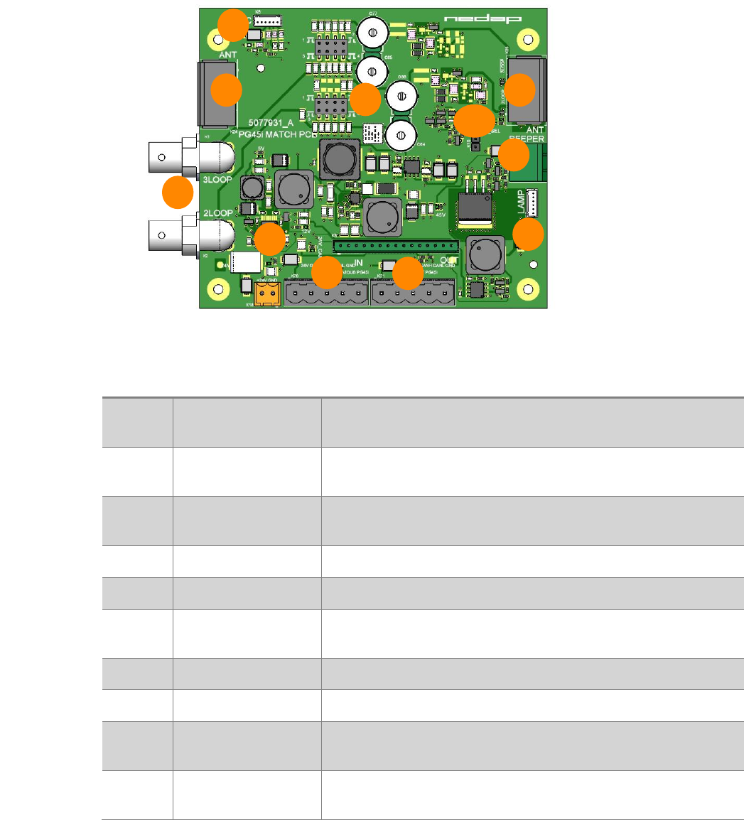
Connections
During installation connections are made to the match PCB, and in some occasions to the EcoReader
PCB. These connections are listed below, together with a description what they are used for.
Match PCB
Figure 2 - match PCB
Number
Component
Description
1
External power
adapter in
Input connector for the external power supply
2
Communication
cable in
Communication cable input coming from the previous PG45i
3
Communication
cable out
Communication cable output to the next PG45i
4
RF inputs
Connected to RF outputs on EcoReader PCB
5
Antenna wire input
Connectors for the antenna wires
6
Customer counter
connector
Connector to the integrated customer counter and lights
7
Top lamp connector
Connector for the top lights
8
Beeper connector
Connector for the buzzer for audible alarms
9
Tuning trimmers &
shunts
Used for matching the antenna to a 50Ω load
10
Antenna selection
led
Led which indicates which ‘antenna’ is selected. Off=3loop,
On=2loop
1
2
3
4
5
5
6
7
8
9
10
0
13
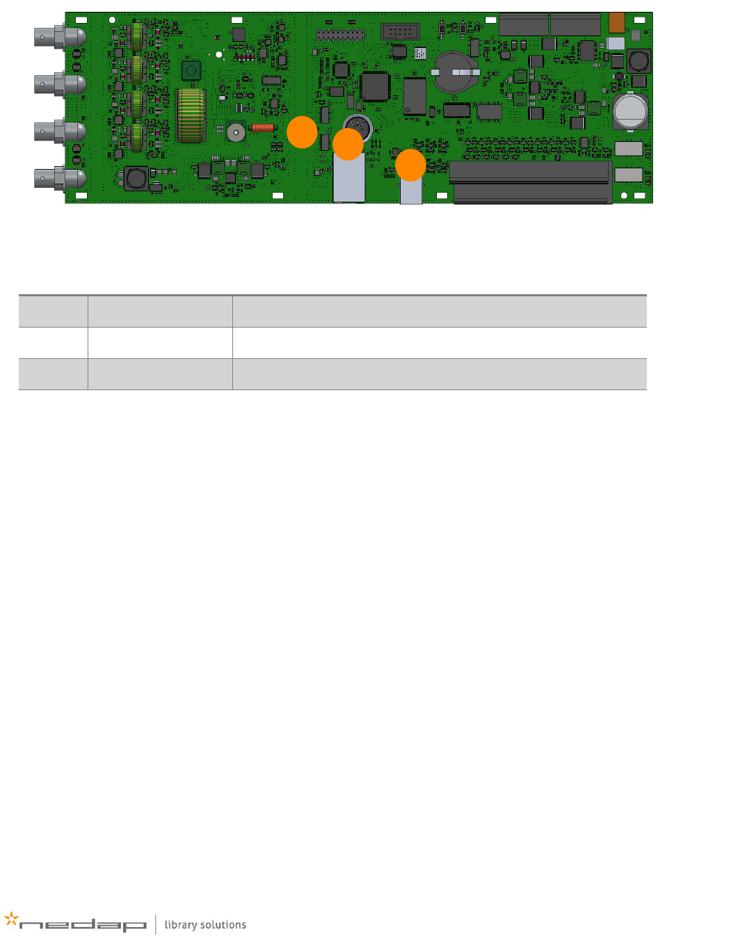
EcoReader PCB
Figure 3 - EcoReader PCB
Number
Component
Description
1
LAN connector
RJ45 connector for ethernet
2
USB connector
USB service connector
3
Tx Led
LED indicator for Tx Power. Off=power on, On = power off
1
2
3

14 www.nedaplibrary.com
Installation
Preparing
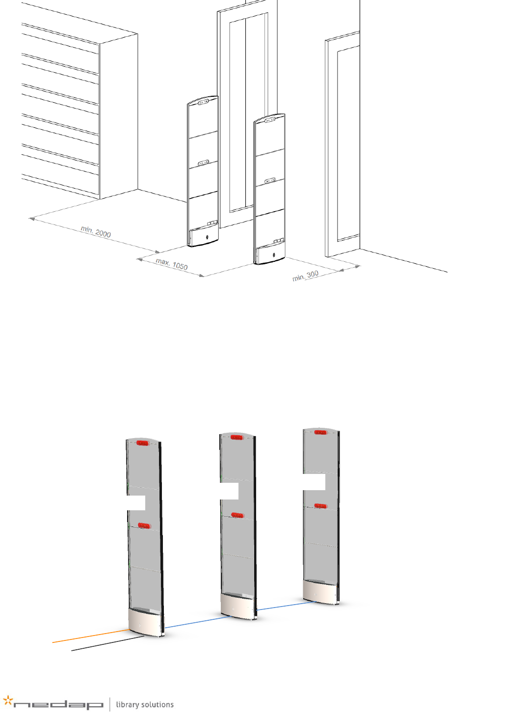
When preparing an installation of a PG45i gate system, the following should be taken into account:
The distance between two gates can be maximal 1050mm or 3 ft. 5”, but is strongly
dependent on environmental influences and tags.
In a range of 2000mm (6 ft 7”) within the gates, no RFID labels with an active alarm may be
present. In some exceptions metal can be used to shield labels, which are placed closer than
the 2 meter radius.
The distance between the gate and the entrance is minimal 300mm (1ft). Take this into
consideration before the preparation of the cabling in the floor.
Since large metal objects or metal frames (doors, sliding doors) might detune the gate, it is
recommended to measure the SWR of the gate after installation. When an SWR bigger than
>1.5 is measured, the gate will perform better when tuned. More information about the SWR
can be found in the section about ‘Measuring and Testing’.
The de-tuning of the gate by a nearby door or sliding door might be different depending on
the position of the door (open or closed). Before tuning, put the door in the position in which
the gates must have their optimal performance.
Automatic doors with electric motors might cause interference on the RFID system,
depending on the motor type. However practical experience has learned that in most cases
this interference is negligible when minimal distances are followed.
A maximum of 16 PG45i gates can be connected to each other
A maximum of 3x PG45i gates can be powered from one power supply. When more gates are
used, power supplies must be added.
In case of any doubt about the local wiring, consult a local licensed electrician and make sure
that it meets local and national codes.
The images in this document may differ slightly from the actual product, you are
installing. However the installation procedure remains the same.
15
Figure 4. PG45i environment
System overview
In a PG45i system the gates are connected for communications and power. The first gate is called the
master and each subsequent is called a slave. The gates have to be configured as such, for the
system to work properly. See Figure 5 for an example of a dual aisle system consisting of three gates.
Figure 5 PG45i dual aisle system
Communication cable
Communication cable
External power
Ethernet cable
Master
Slave
Slave
16 www.nedaplibrary.com
When more than four PG45i gates are used in a system, like the example in Figure 6, an extra power
supply must be added to every third gate, which make this gate a ‘powered slave’. Check the table in
Appendix A for larger setups.
Figure 6 PG45i four aisle system
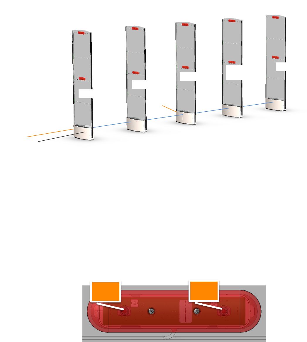
Customer counting overview
Customer counting in the PG45i gate is done with infrared beams: one gate has an infrared
transmitter and the opposite gate has two receivers, which detect the beam from the transmitter.
When a customer passes through the gates, the beams are interrupted and the order of interrupt of
the two receivers, determine the direction of the customer.
Thus in order to have a proper working customer counter setup, the gates must be mounted in such a
way that the transmitter is directing towards a receiver.
- The receiver side of the customer counter module can be identified by locating the side with
the two ‘screws’. See Figure 7
- The transmitter side is logically the other side, it can be detected by the Plexiglas holders
and the transmitter opening. See Figure 8.
Figure 7 - receiver side of customer counting module
Communication cable
Communication cable
External power
Communication cable
Communication cable
Ethernet cable
External
power
receiver
receiver
Master
Slave
Slave
Powered
Slave
Slave
17
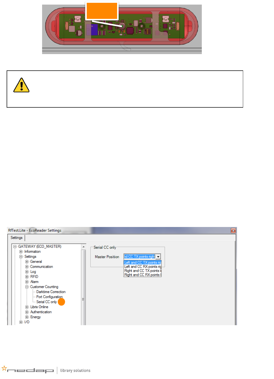
Figure 8 - transmitter side of customer counting module
A PG45i system is designed in such a way that the aisle numbering is always the same (this is done
so all systems behave and function in the same, predictable way, which simplifies troubleshooting).
Looking from outside the library, inside the library building, aisle 1 is always the left-most aisle. Aisle
2 is the next, etc. Refer to Figure 10 for a diagram of this.
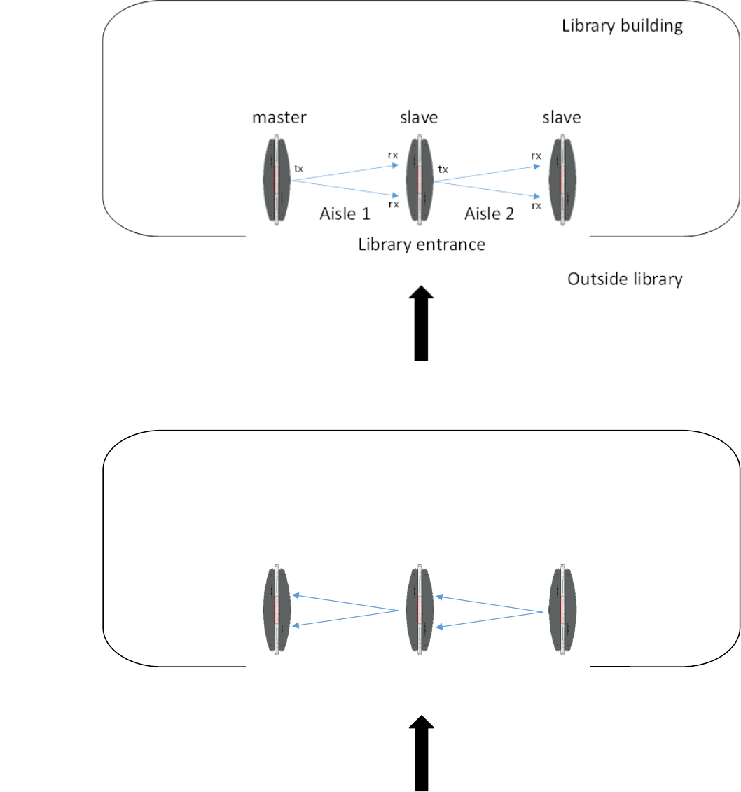
In Figure 10 the master is the left-most gate and the transmitter of the master is directing towards
the first slave. In Figure 11 the master is also on the left, but the customer counting of the Master is
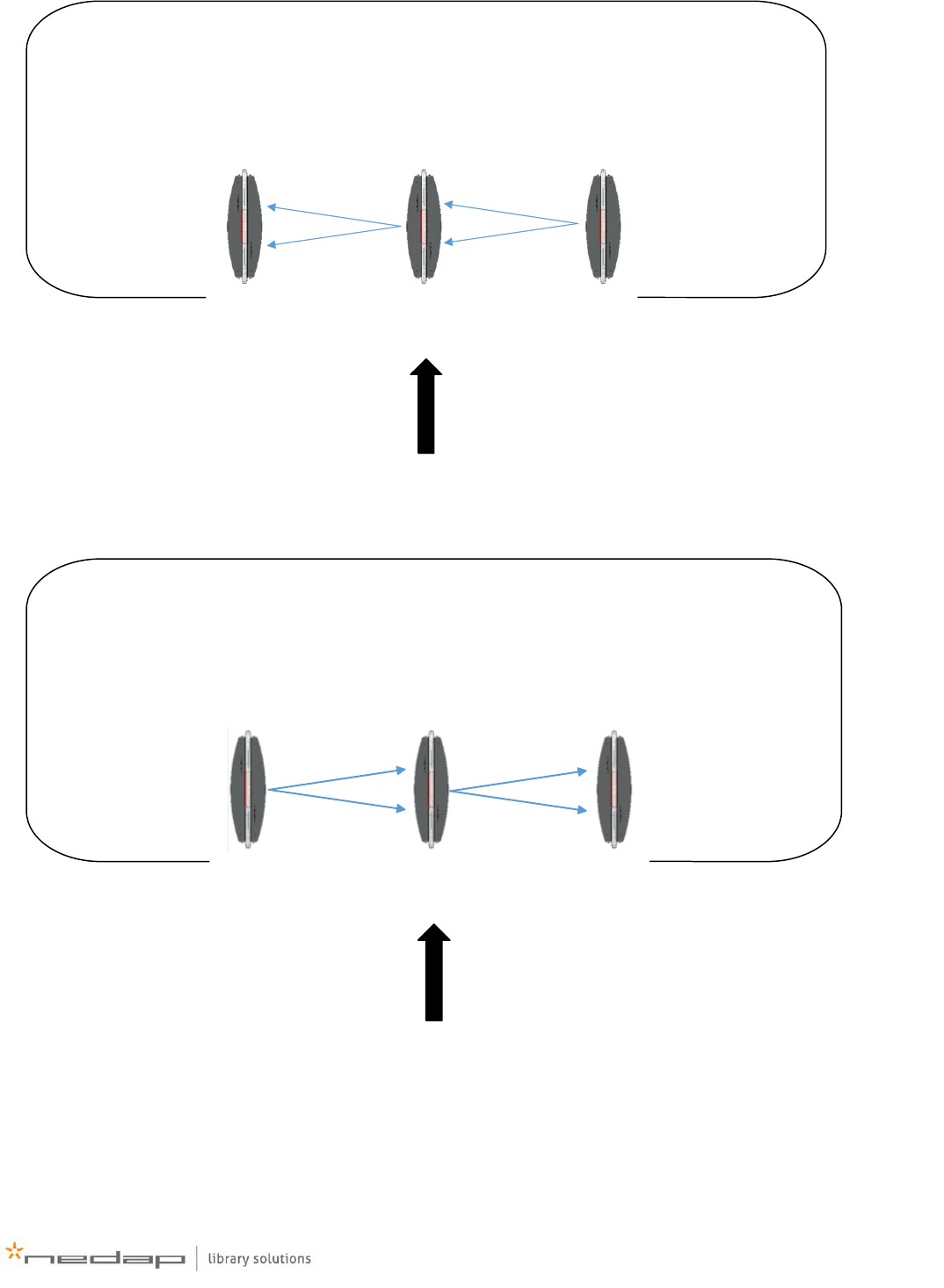
receiving. In Figure 12 the master is on the right, and it is transmitting towards the first slave. In
Figure 13 the master is the right-most gate, but its receiver is directed toward the first slave.
In order for the aisle numbering and incoming/outgoing customer counting to be correct the master
and all of the slaves have to be configured correctly, which means that the gates must know if the
master is positioned left or right, and if its transmitter or receiver is pointing to the first slave. The
settings can be altered under Settings > Customer Counting > Serial CC only > Master position (see
Figure 9).
Figure 9 – setting in RFTest.Lite to change master position and RX/TX of master.
The customer counting modules are mounted in a fixed position inside each gate. It is
not possible to install them in any other way, so make sure that the gates are properly
aligned before mounting them to the floor, so the transmitting and receiving sides are
pointing in the correct direction.
transmitter
1
18 www.nedaplibrary.com
Figure 10 - aisle numbering for customer counting, master left, transmitting. Master position: ‘Left and CC TX points right’
Library building
Outside library
Aisle 1 Aisle 2
Library entrance
master slave slave
tx
rx
rx
tx
rx
rx
Figure 11 - aisle numbering for customer counting, master left, receiving. Master position: ‘Left and CC RX points right’
19
Library building
Outside library
Aisle 1 Aisle 2
Library entrance
masterslaveslave
tx
rx
rx
tx
rx
rx
Figure 12 - aisle numbering for customer counting, master right, transmitting. Master position: ‘Right and CC TX points left’
Library building
Outside library
Aisle 1 Aisle 2
Library entrance
slave slave master
tx tx
rx
rx
rx
rx
Figure 13 - aisle numbering for customer counting, master right, receiving. Master position: ‘Right and CC RX points left’
20 www.nedaplibrary.com
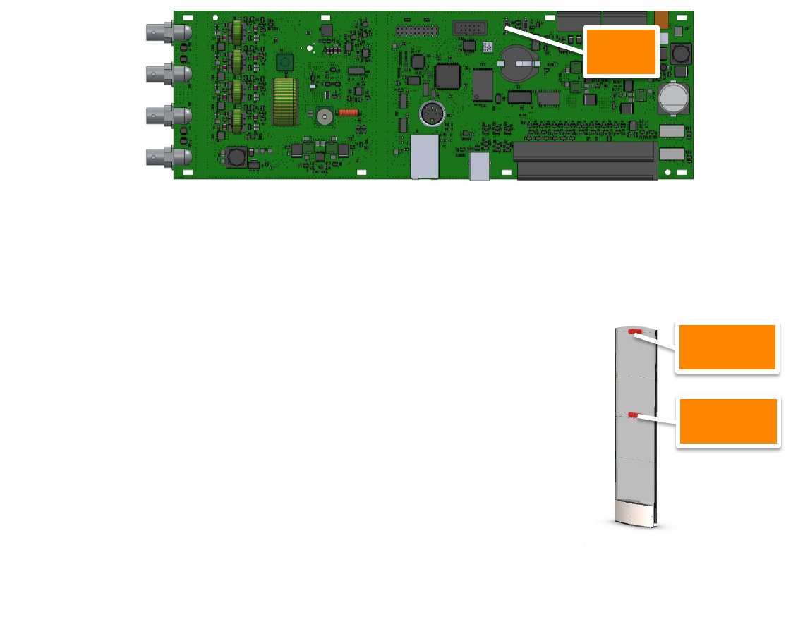
Testing the customer counting direction
The Pg45i can show if the direction for the gates in configured correctly without having to use
special software. Press the test button for approximately 1 second on the Eco Reader (Figure 14). The
Eco Reader can be found in the foot (Figure 20). All lights will light up, and stay on. The test mode is
now active. Test mode will deactivate after a 1 minute idle time.
Figure 14 – Test button on Eco Reade inside PG45i
Walk through the gate (without any items) and the top LED of the receiving gate will blink in one of
the following patterns:
- 4 times slowly (1 second ON, 1 second OFF, etc.)
This notifies that this direction is registered as an incoming
customer.
- 8 times fast (0.5 seconds ON, 0.5 seconds OFF, etc.)
This notifies that this direction is registered as an outgoing
customer.
After blinking, the top LED of the receiving gate will return to a continuous
mode, to indicate that it is still in testing mode. The test mode will stop
after 1minute idle time, and test mode cannot be stopped manually. After
testing the PG45i’s will return to its normal working state.
If the direction is not as how you want it to be, check your settings from
Figure 9, and if you have selected the same setting for every gate (so also
for the slaves).
Test
Top LED
Middle LED
Figure 15 – All LED’s will be lit
continuously in testing mode. Top
LED of receiving gate will blink to
show customer counting settings.
21
Mounting the gates
When all of the components are collected, and the preparations for the cabling are done correctly,
you can walk through the following steps to mount the gates.
Please note that mounting equipment like screws, bolts, anchors or plugs are not
delivered with the gates. Please consult your local installation regulations on how to
mount the PG45i gates.
With each PG45i gate a communication cable of 2m/79” is delivered. Make sure that
this cable is either fitted through floor tubing or a floor mounted threshold.
With each gate a mounting plate is delivered. This plate can be used as a template to
drill the mounting holes in the floor or as a spacer to create some room for cabling
between the floor and the side plates. This can be useful when a floor mounted
threshold is used, in case cabling can’t be run through the floor.
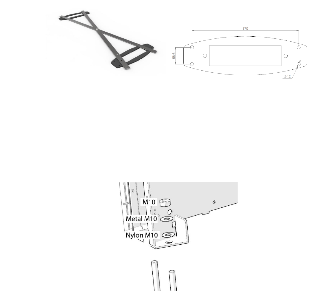
A mounting frame set (art.nr.7599986) can be ordered from Nedap Library Solutions,
which can aid during the installation. With this frame set the mounting plates can be
distanced evenly from each other at 90cm, 105cm & 120cm. In the instructions below it
will be assumed that this mounting frame set is used.
When installing in a region which requires FCC or IC approval, you will always need to
mount the PG45i on the specially designed foot, which can be ordered with article
number 7603282. The gate will be heightened to a total height of 180cm. This can be
mounted to the floor the same way as the gates.
22 www.nedaplibrary.com
1. Use the mounting frame set and two mounting plates to position the gates in the building.
Use a laser pointer to align the gates to the building. Refer to Figure 16.
Figure 16 - mounting frame set and
mounting plates
Figure 17 - Holes that need to be drilled in floor
2. Drill the marked holes using the holes in the mounting template.
3. Clean the holes and place the anchors (to which the gates will be bolted to) according to
anchor specifications.
4. Make sure that the cabling for the gates is available.
5. Remove the side metal panels on the base of the PG gate. Mount the gates in place and
secure them tightly to the anchors.
Figure 18 – example of bolting gates
23
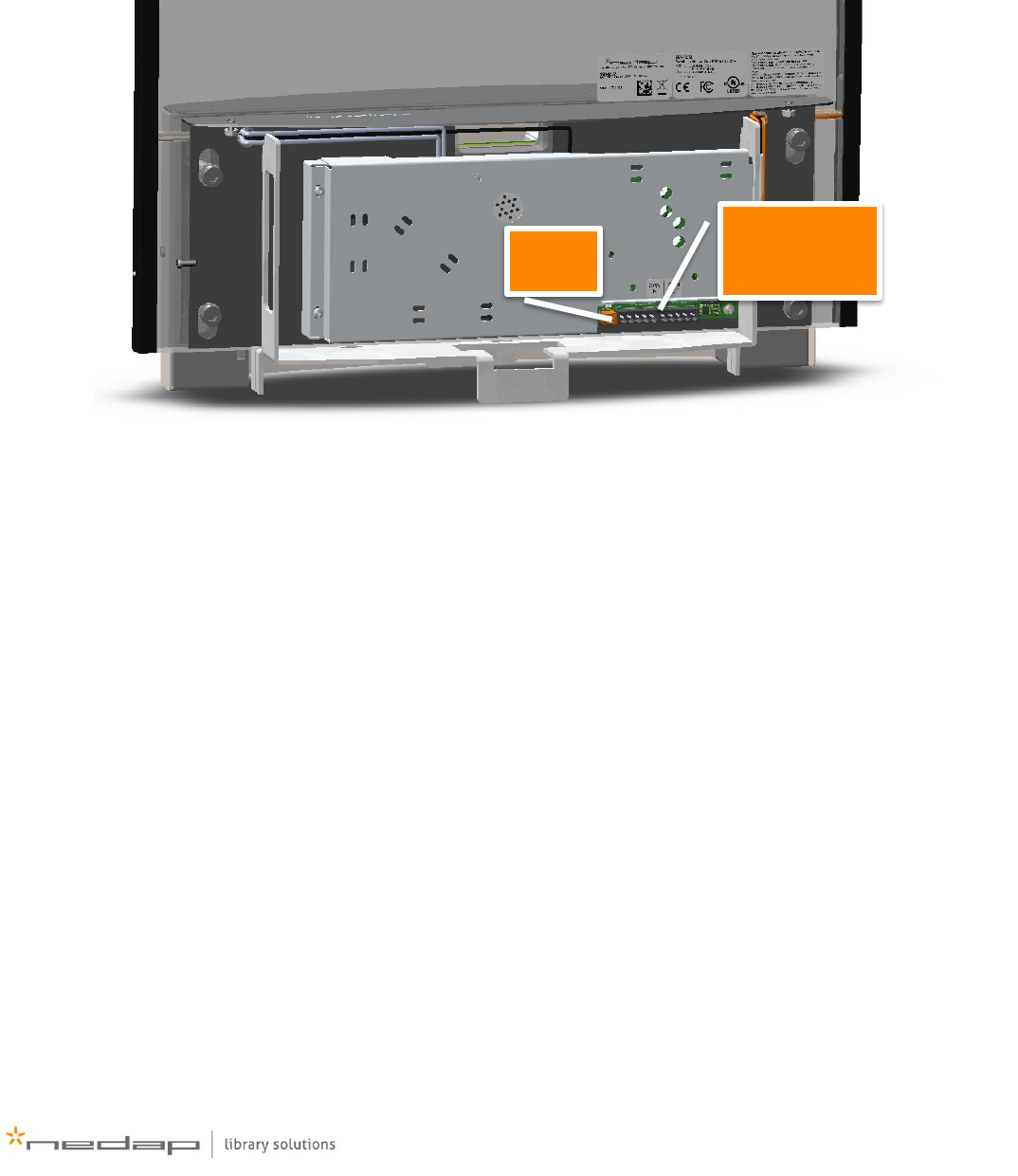
Cabling the gates
Master
1. Locate the master gate and the side with the match PCB.
Note: the match PCB is on the side of the PG45i with the nameplate sticker
2. Connect the power supply to the power supply connector on the match PCB. See Figure 19
for its location.
Figure 19 - PG45i match PCB location
3. Connect the CAN cable to the CAN OUT connector, which is the right connector on the match
PCB. See Figure 19 for its location.
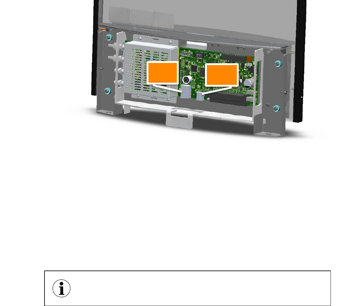
4. Locate the side of the gate with the EcoReader
power
CAN IN & OUT
24 www.nedaplibrary.com
5. Connect an Ethernet cable or USB cable (if applicable) to the EcoReader. Refer to Figure 20.
Note: USB cable is only used during servicing the gate.
Figure 20 - PG45i EcoReader PCB location
Slave
1. Locate the side with the match PCB of the slave
Note: the match PCB is on the side of the PG45i with the nameplate sticker
2. Connect the incoming communication cable of the previous master or slave to the CAN IN
connector on the left. See Figure 19 for its location.
Powered slave
1. For a powered slave follow the instructions for a normal slave.
2. Connect the power supply to the power supply connector on the match PCB. See Figure 19
for its location.
For a (powered) slave no connection needs to be made to the EcoReader. Only for
servicing purposes a Ethernet or USB cable could be connected.
ethernet
usb
25
Settings configuration
Configuration can be done with Rftest.Lite over USB or network or with the internal webpage of the
EcoReader inside the PG45i.
1. Connect with RfTest.Lite to the master gate and retrieve its settings by clicking on the
‘Tuning’ button.
During first installation only the settings of the master will be shown, since it is not actually
configured as master and therefor it will not show settings from its slave.
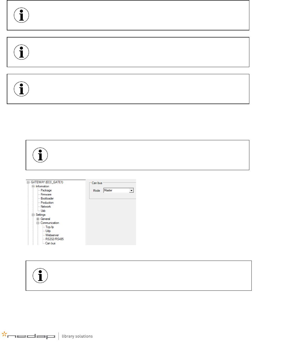
2. Navigate to ‘GATEWAY>Settings>Communication>Can bus’ and set mode to ‘Master’
3. The system needs to be restarted now. Do this by unplugging and replugging the power to
the master. Alternatively issue the reboot command 12RM=0| with RfTest.Lite.
Currently it is only possible to configure the local gate over the webpage. It is not
possible to configure the other gates with the webpage. RfTest.Lite must be used for
this.
Use RfTest.Lite 3.2.0 or newer to configure a PG45i system. Please refer to the
Rftest.Lite manual for instructions on how to use RfTest.Lite
This manual describes the configuration steps that need to be done using RfTest.Lite
A PG45i gate leaves the factory configured as slave. In this way only the master
needs to be set to ‘master’ during installation.
When everything is configured correctly, the master will now switch on all the
slave gates one-by-one.
26 www.nedaplibrary.com
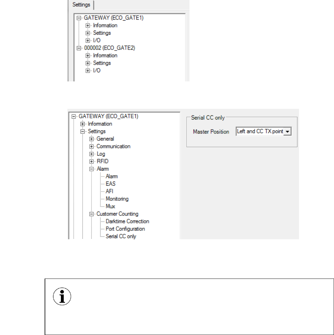
4. Reconnect with RfTest.Lite to the master and retrieve its settings. The master’s and all slave’s
settings appear now.
5. Navigate to ‘GATEWAY>Settings>Customer Counting>Serial CC only’ and configure the
location and orientation of the master for correct customer counting. See paragraph
‘Customer counting overview’ for more information.
Now the system is configured at a minimum to start scanning. Next each gate (master and slave(s))
need to be configured to use the right alarming type (EAS\AFI) and their antenna power needs to be
turned on.
Perform the following steps for each gate:
The following settings are forced during startup to a specific value. They can be
changed, but after a restart they will be switched to their default value:
- ‘Settings>Rfid>Synchronization>Synchronization’
- ‘Settings>Alarm>Mux>External mux’
- ‘Settings>Alarm>Mux>Antennas’
27
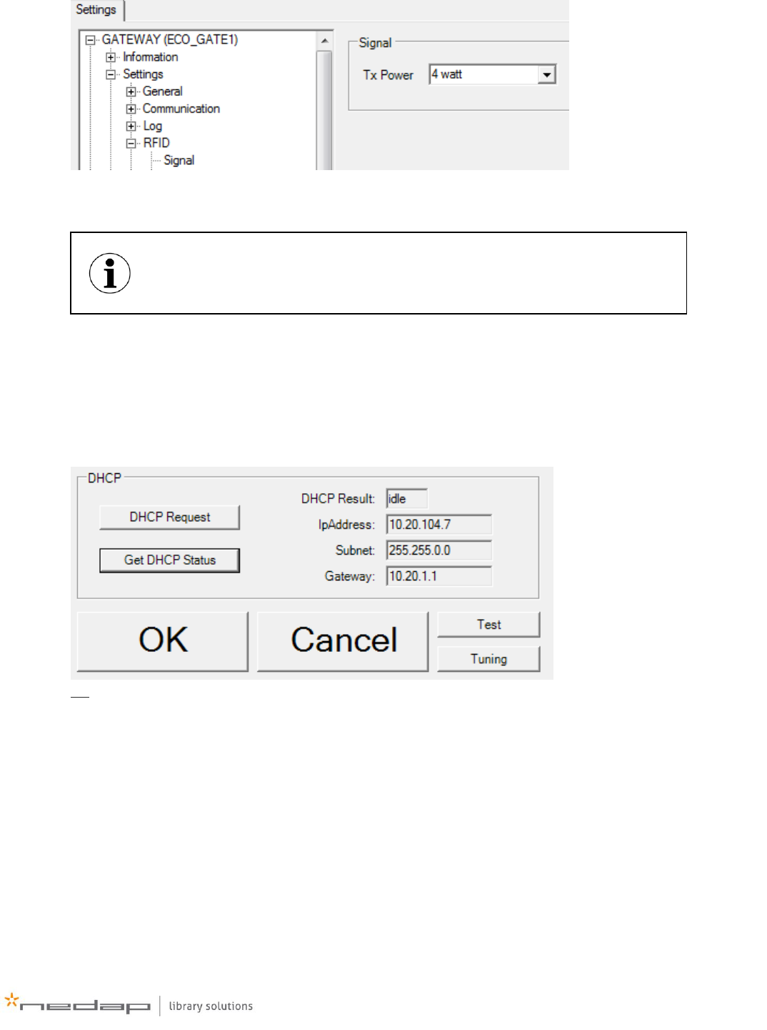
6. Navigate to ‘Settings>RFID>Signal’ and set the Tx Power to 4 watt
7. Navigate to ‘Settings>Alarm>Alarm’.
Make sure Alarm is enabled, select the alarm type, select the action on an alarm, set the
buzzer volume and configure the activation time of the relays, lamps in the gate and buzzer.
When the master gate is connected to the network and\or Librix Online, the master’s IP address and
Librix Online settings need to be configured:
8. To set a static IP, configure DHCP or retrieve the assigned DHCP address, connect to the
master with USB and RfTest.Lite
9. On the communication setup window, click on ‘Get DHCP status’ to get the currently
assigned IP, either static or DHCP.
OR
The buzzer is limited in hardware to a activation time of max. 1second. Any
longer time configured in software will be overridden by the hardware.
28 www.nedaplibrary.com
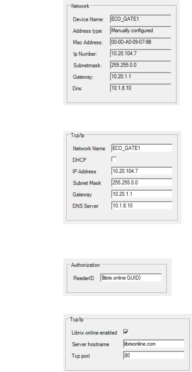
Go to the settings window and navigate to ‘GATEWAY>Information>Network’
10. To configure the IP address, click Tuning to retrieve the settings and for the master gate
navigate to ‘Settings>Communication>TCP/IP’ and in the window set all the appropriate
settings
11. To configure the Librix Online connection, make sure that an EcoGate device in Librix Online
is created and its GUID is written down.
12. Navigate to ‘Settings>Librix Online>Authorization’ and enter the Librix Online GUID in the
ReaderID field.
13. Navigate to ‘Settings>Librix Online>TCP/IP’ and make sure Librix Online is enabled, the
server hostname is ‘librixonline.com’ and the port is set to ‘80’

29
System operation
When the system is configured correctly, the master and slaves should start multiplexing. On the
EcoReader this can be seen by a blinking ‘TX LED’ (see Figure 3) and on the match PCB by a blinking
antenna selection led (see Figure 2).
When an alarm-enabled tag is held next to each gate, an alarm should be detected at this point.
When the system is not working:
- Check the CAN, Synchronization, Mux and alarm settings of each gate and make sure they are
correct.
- Check if each slave is powered and stays powered. When it appears that they are switching
on and off, the power supply might not be able to power the entire system. Replace it with a
power supply with a higher output rating or add extra power supplies.

30 www.nedaplibrary.com
APPENDIX A.
Amount of gates in
your setup (aisles)
Amount of power
supplies needed
Gates (counted from master, where master = 1)
that need extra power supply
1 (0 aisles)
1
1
2 (1 aisles)
1
1
3 (2 aisles)
1
1
4 (3 aisles)
2
1, 3
5 (4 aisles)
2
1, 3
6 (5 aisles)
3
1, 3, 5
7 (6 aisles)
3
1, 3, 5
8 (7 aisles)
4
1, 3, 5, 7
9 (8 aisles)
4
1, 3, 5, 7
10 (9 aisles)
5
1, 3, 5, 7, 9
11 (10 aisles)
5
1, 3, 5, 7, 9
12 (11 aisles)
6
1, 3, 5, 7, 9, 11
13 (12 aisles)
6
1, 3, 5, 7, 9, 11
14 (13 aisles)
7
1, 3, 5, 7, 9, 11, 13
15 (14 aisles)
7
1, 3, 5, 7, 9, 11, 13
16 (15 aisles)
8
1, 3, 5, 7, 9, 11, 13, 15

31
Frequently Asked Questions
Question
1.
- Aisle width
Can I mount the gates closer together, than the recommended aisle distance?
Answer:
When possible, it is recommended to place the gates closer together. This will improve the density of
the detection field.
Question
2.
- Nearby objects
Can I mount the gates close to other objects?
Answer:
Although the PG45i gates were developed to be as insensitive as possible to outside disturbances,
Nedap advises to follow the recommended distances from metal objects as outlined in this
document. Nearby automatic doors or metal frames might cause de-tuning of the gates, which means
they need to be tuned. In extreme cases tuning might not be possible, since the de-tuning is outside
the range of the gates. However when the gates are installed within a standard library environment,
this situation will be extremely rare.
Question
3.
- Latest version of manual
Where can I find the latest version of this document?
Answer:
This documents can be found on the Nedap Library Solution support site or contact Nedap directly.
Contact details can be found in the beginning of this document.

32 www.nedaplibrary.com
Question
4.
- Installation time
How much time will an installation take?
Answer:
Installation time depends heavily on local conditions, like floor type, cabling conduit availability, etc..
However after the actual mounting of the gates and cabling, very less time is needed to configure the
reader. The only major settings are setting the alarm type (EAS or AFI) and the amount of connected
gates.
Let’s assume that 2x PG45i gates with an EcoReader must be installed. When the following
conditions are met, the total installation time will be around 0.5-1hours:
- concrete floor, which can be drilled in
- chemical plugs used
- cable conduits are present and ready for cabling
Question
5.
- Mounting
Can I mount the gates on a metal floor or steel reinforced concrete floor?
Answer:
Detection
Nedap PG45i gates are designed to not be affected by their surroundings, including any metal floors,
when it comes to detection. Besides that, a well-grounded metal floor provides a ground for the gate
which improves the balance of the gate. A well balanced gate will radiate the power that is supplied
to it, instead of reflecting it back to the reader. And in the end we want the power to be radiated to
improve the detection, instead that it is reflected back to the reader.
Mounting
The PG45i gates are supplied without anchors or bolts. The best suitable anchor should be chosen
for the used flooring and the mounting instructions of the anchor should be used. When no drilling in
the floor is allowed, a metal, wooden or any other mounting plate can be used.
Question
6.
- Network connection problem
I cannot contact the PG45i’s EcoReader over its web interface
Answer:
Make sure the EcoReader is configured for DHCP or has a valid static IP address assigned to it. This
can be done by connecting a pc or laptop to the EcoReader over the USB connection and by using
the configuration and diagnostic tool RfTest.Lite.
Question
7.
- CC module problem
The PG45i gate’s EcoReader is not showing the settings I expect or is not multiplexing anymore.
Answer:

33
If the CC module is not connected correctly, the EcoReader inside the PG45i does not know it is in a
PG45i gate and it will not act accordingly. If this is the case please check if:
- the connectors from match PCB to customer counter modules are connected correctly
- if the customer counter module is defective. The fastest and easiest way to do this, is by
checking if a led is burning on the module.
Question
8.
- Power supply problem
A part or the entire system is not working. There are no LEDs burning on the EcoReaders and match
PCB’s in some or all of the pg45i gates.
Answer:
In a system with one power supply, this power supply might be defective.
In a system with more than one power supply, and the master’s supply is defective, nothing will work,
since the master controls the entire system.
In a system with more than one power supply, and a powered slave’s power supply is defective, the
gates after the powered slave will not operate anymore. The system will work from master up to the
powered slave.
Question
9.
- Customer Counting direction testing, lights go off in test mode
With the PG45i it may happen that some of the lights will go off during the test mode.
Answer:
When the PG45i is in test-mode, and it will detect an item during this test mode, it will alarm and
then turn off the light of that gate. At this point, the test-mode is still active but only the lights are off
on some of the gates. If you want to prevent this from happening, you will need to make sure that
there are no (alarming) items near the gate during the testing procedure.