Nedap N V RTLACTN Neck Tag Act RT User Manual Installation Manual sow feed station
N. V. Nederlandsche Apparatenfabriek NEDAP Neck Tag Act RT Installation Manual sow feed station
14_PS1912 RealTime Heat detection service manual GB v1.7 CGDRTLACTN
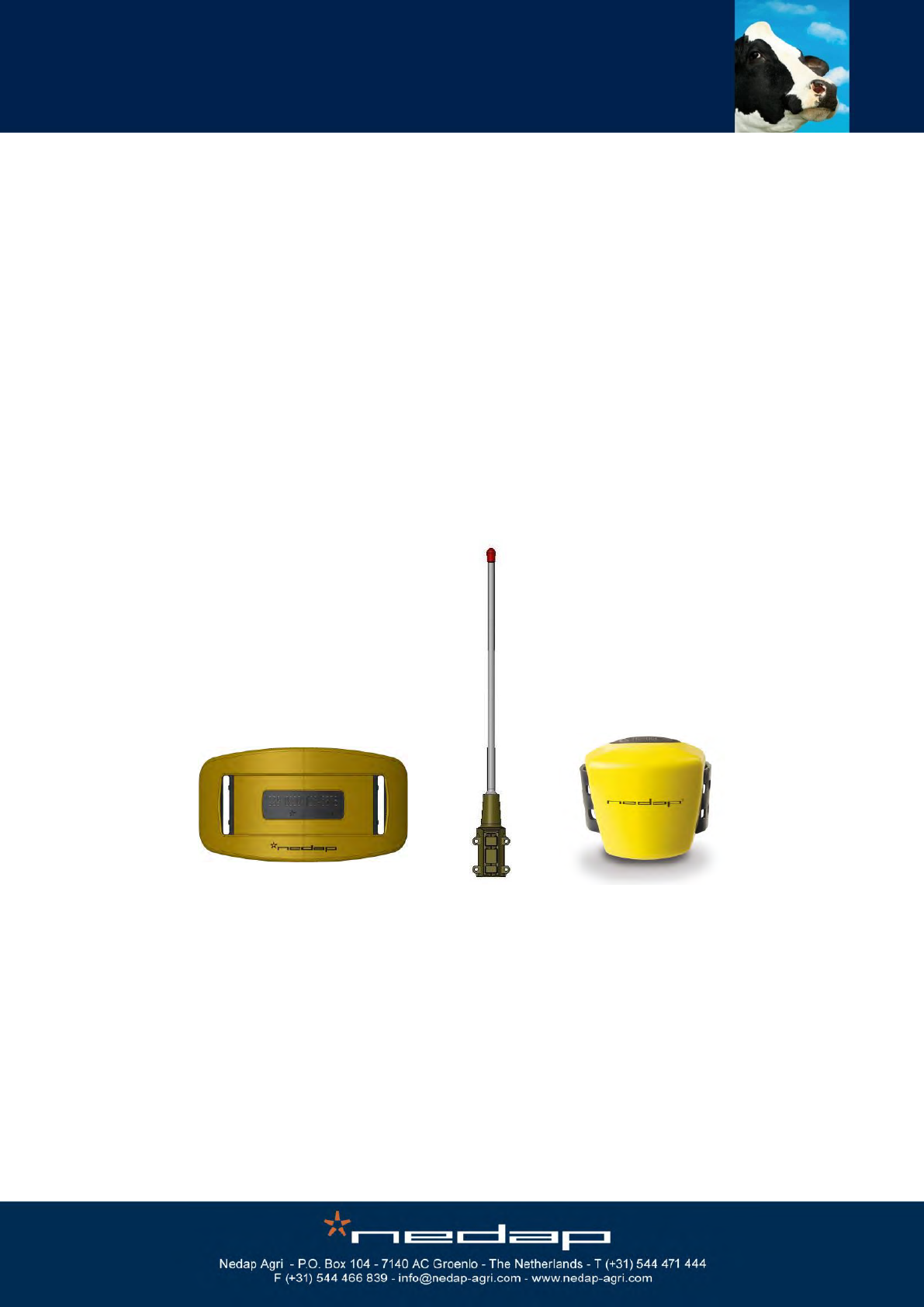
Nedap Velos
RealTime Heat detection
Manual article number 5278902 06 - 2013 / Manual version 1.7
Service manual
For installation, operation and service

Nedap Velos – RealTime Heat detection service manual GB Manual version 1.6

Nedap Velos – RealTime Heat detection service manual GB Manual version 1.6
Version overview
Manual version 1.0 / 06 - 2011
First release.
Manual version 1.1 / 10 - 2011
RealTime FCC and IC warning.
Manual version 1.2 / 01 - 2012
Manual updated for Velos 3.00
Manual version 1.3 / 07 - 2012
Updated safety warning, service and user information.
Manual version 1.4 / 08 - 2012
Updated VPU LAN connection
Manual version 1.5 / 01 - 2013
Updated mounting instructions
Manual version 1.6 / 01 - 2013
Updated service password
Manual version 1.7 / 06 - 2013
Update for Eating monitoring
FCC ID: CGDRTLACT / CGDRTLACTN
IC: 1444A-RTLACT / 1444A-RTLACTN
Compliance statements (part15.19)
This device complies with part 15 of the FCC Rules and to RSS210 of Industry Canada.
Operation is subject to the following two conditions:
(1) this device may not cause harmful interference, and
(2) this device must accept any interference received, including interference that may cause undesired operation.
Cet appareil se conforme aux normes RSS210 exemptés de license du Industry Canada. L'opération est soumis aux
deux conditions suivantes:
(1) cet appareil ne doit causer aucune interférence, et
(2) cet appareil doit accepter n'importe quelle interférence, y inclus interférence qui peut causer une opération non pas
voulu de cet appareil.
Warning (part15.21)
Changes or modifications not expressly approved by party responsible for compliance could void the user’s authority to
operate the equipment.
This in particular is applicable for the antenna which can be delivered with the System.
This information is furnished for guidance, and with no guarantee as to its accuracy or completeness; its publication conveys no
license under any patent or other right, nor does the publisher assume liability for any consequence of its use; specifications and
availability of goods mentioned in it are subject to change without notice; it is not to be reproduced in any way, in whole or in part,
without the written consent of the publisher.
© Nedap N.V., AGRI P.O. Box 104 NL-7140 AC GROENLO The Netherlands

Nedap Velos – RealTime Heat detection service manual GB Manual version 1.6
Preface
This manual describes the installation, operation, troubleshooting and maintenance of the
RealTime Heat detection system. Read this manual entirely and when installing, carefully follow
the instructions step by step as described in the manual.
Conventions
Abbreviations used in this manual:
RT
RealTime (used for motion sensor type)
VP
V-pack
Pictograms
Please pay extra attention here. This pictogram indicates an important subject.
More information
Later versions of this document will be posted to the Nedap Agri Website, as required.
Please visit our website (http://www.nedap-agri.com) for more information or to find
related manuals.

Nedap Velos – RealTime Heat detection service manual GB Manual version 1.6
Table of contents
Preface and Version overview
Table of contents
1. Introduction and description ............................................................................................. 1
2. Working/Functioning .......................................................................................................... 2
3. Safety.................................................................................................................................... 3
3.1. Safety warnings ..................................................................................................................... 3
3.2. Safety precautions during installation .................................................................................... 3
3.3. Animal welfare and safety ..................................................................................................... 3
4. Installation ........................................................................................................................... 4
4.1. Mounting the V-box 1 and the V-box 2 on the wall................................................................ 4
4.2. Mounting the antenna............................................................................................................ 4
5. Starting up operation .......................................................................................................... 5
5.1. Connecting the process unit .................................................................................................. 5
5.2. Connecting the antenna ........................................................................................................ 7
5.3. Connecting the PC or network .............................................................................................. 7
5.4. Connecting the power ........................................................................................................... 8
5.5. Setting up the VPU network configuration ............................................................................ 8
5.6. Setting up the VPU software ................................................................................................. 8
6. Start up operation VPU program ....................................................................................... 9
6.1. First settings .......................................................................................................................... 9
6.2. Entering new animal numbers (and groups) ....................................................................... 11
6.2.1. Entering new groups .............................................................................................. 11
6.2.2. Entering new animal numbers in the system.......................................................... 11
6.2.3. Changing the responder number and/or basic data ............................................... 12
6.3. Heat detection attention settings ......................................................................................... 13
6.4. Eating monitor attention settings (neck sensors only)......................................................... 14
7. Operation VPU program ................................................................................................... 15
7.1. Viewing animals in heat....................................................................................................... 15
7.2. Viewing eating monitor attentions (neck sensors only) ....................................................... 19
7.3. Viewing label attentions (neck sensors only) ...................................................................... 20
7.4. Using e-mail notification ...................................................................................................... 21
7.5. Using a mobile phone with Internet connection .................................................................. 21
7.6. Setting up the calendar attentions ....................................................................................... 22
7.7. Viewing calendar attentions ................................................................................................ 23
7.8. Entering calendar data ........................................................................................................ 24
8. Maintenance ...................................................................................................................... 26
9. Malfunctions ...................................................................................................................... 27

Nedap Velos – RealTime Heat detection service manual GB Manual version 1.6
10. Disposal ............................................................................................................................. 28
Appendix A Technical specifications .................................................................................. 29
Appendix B Restore factory defaults .................................................................................. 30
Appendix C Setting the VP4101 address ............................................................................ 31
Appendix D VP4101 Display ................................................................................................. 32
Appendix E Mounting the V-box .......................................................................................... 33
Appendix F Installing more than one antenna ................................................................... 35
Appendix G Mobile access ................................................................................................... 38
Appendix H Setting up the VPU network configuration .................................................... 40
Appendix I Using synchronisation with a Nedap server ................................................. 42
Appendix J Declaration ........................................................................................................ 43
Nedap Velos – RealTime Heat detection service manual GB Manual version 1.6 / Page 1
1. Introduction and description
The behaviour of an animal in heat is quite different from her normal behaviour. The activity
measurement monitors the changes in the behaviour of the individual animals day and night and
it will detect animals that are in heat.
The activity of the animals can be with measured with RealTime motion sensors. The antenna in
the barn receives the activity information from the RealTime motion sensor of the individual
animals. The Velos program determines the activity increase of an animal. If an animal is a lot
more active than usual it will get an activity attention. The red light on the process unit will
indicate this attention. The Velos program displays overviews of animals with a clear increased
activity on a PC screen or on a mobile phone.
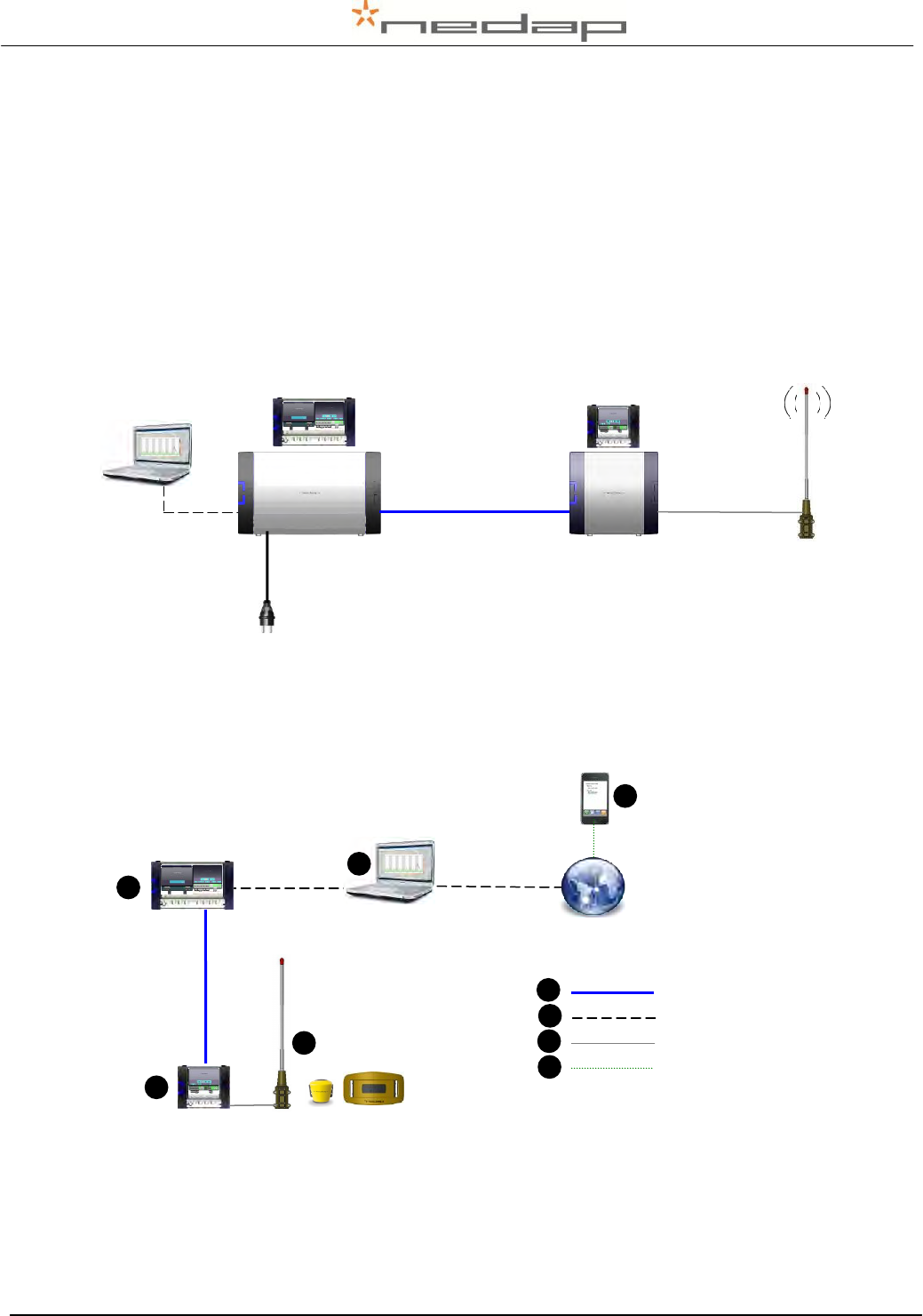
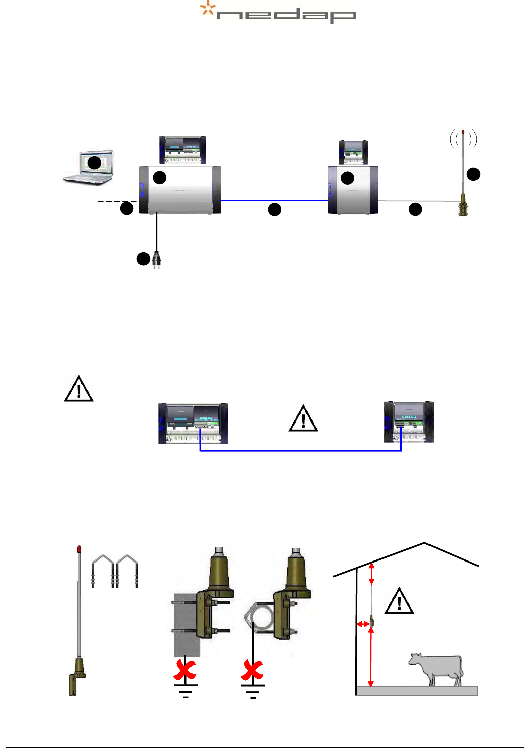
Figure 1. Overview RealTime system with cable distances
The RealTime system consists of one or more antennas and a process unit connected to a PC
or network. This system works with RealTime motion sensors only.
1. Antenna for reading RT
Activiity data
2. Reader
3. Velos Process Unit
(VPU)
4. PC connection or
Network connection
via LAN network
5. Mobile phone with
Internet connection
6. Communication cable
7. Ethernet cable
8. Antenna cable
9. Mobile Internet
connection
Figure 2. Overview RealTime system with cable types used
← 2 m. →
← < 200 m. →
↑
2 m.
↓
3
L
e
n
gt
h
of
c
or
ri
d
or
(
m
)
2
1
L
e
n
gt
h
of
c
or
ri
d
or
(
m
)
5
1
L
e
n
gt
h
of
c
or
ri
d
or
(
m
)
7
1
L
e
n
gt
h
of
c
or
ri
d
or
(
m
)
6
1
L
e
n
gt
h
of
c
or
ri
d
or
(
m
)
4
1
L
e
n
gt
h
of
c
or
ri
d
or
(
m
)
8
1
L
e
n
gt
h
of
c
or
ri
d
or
(
m
)
1
L
e
n
gt
h
of
c
or
ri
d
or
(
m
)
9
Len
gth
of
corr
idor
(m)
Nedap Velos – RealTime Heat detection service manual GB Manual version 1.6 / Page 2
2. Working/Functioning
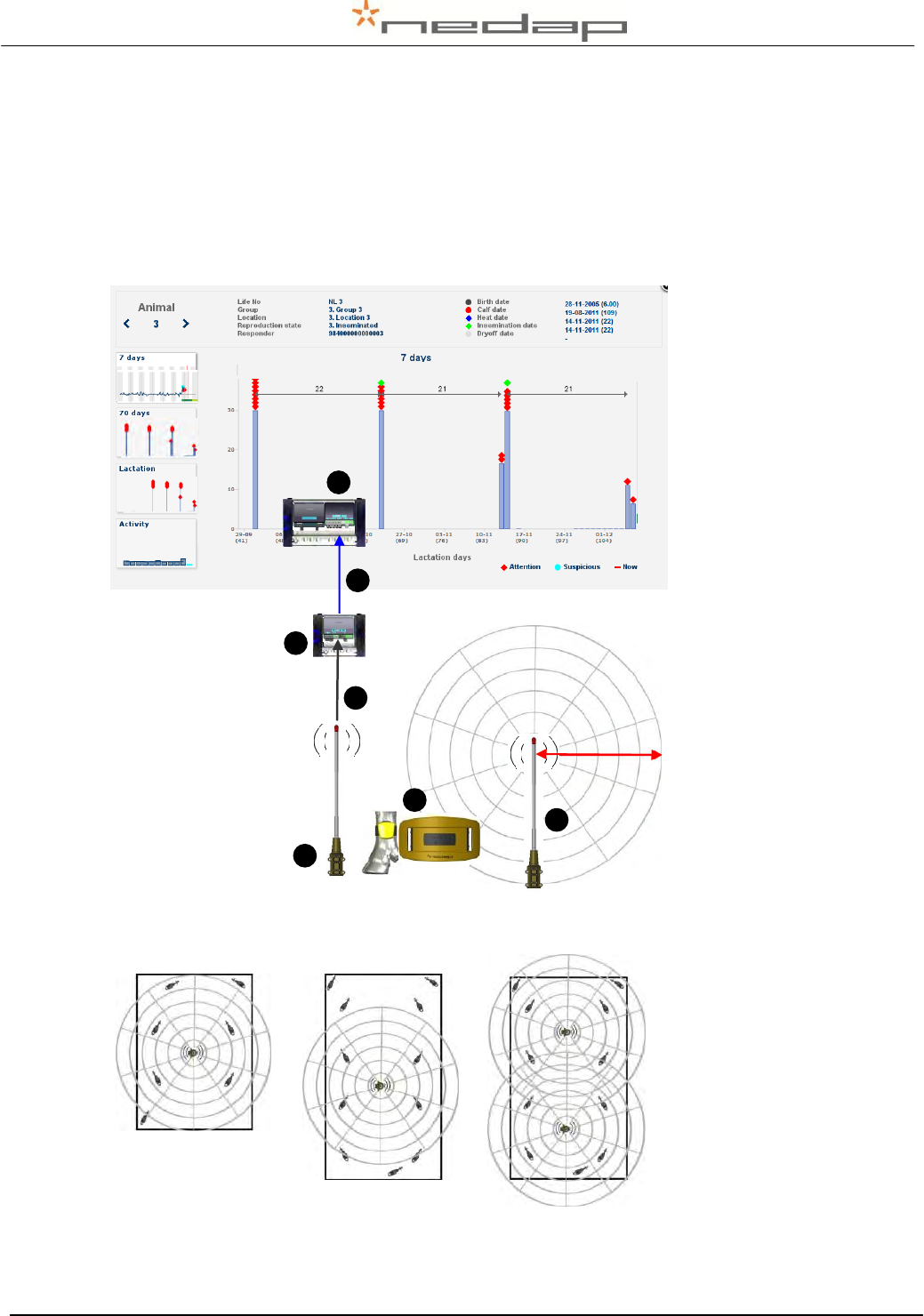
The VP4101 antenna reader collects the activity information and the animal responder number
from every RealTime motion sensor in the antenna reception field and sends it to the Velos VPU
controller program. The RT sensor should be in range of the antenna field at least once every 24
hours to collect all the activity data but more frequent is advisable for accurate attentions. The
reception range of the antenna field is at least 50 meters depending on the housing environment
materials. More than one antenna can be used to reach a larger reception area.
1. Leg / Neck RT motion
sensor
2. Antenna
3. Motion sensor info with
responder number and
activity data
4. Reader
5. VPU controller with
Velos program
Figure 3. Connection between Velos program and RealTime antenna
Figure 4. Examples of possible detection areas of 1 or 2 antennas
50 m.
2
L
e
n
gt
h
of
c
or
ri
d
or
(
m
)
4
L
e
n
gt
h
of
c
or
ri
d
or
(
m
)
2
L
e
n
gt
h
of
c
or
ri
d
or
(
m
)
3
L
e
n
gt
h
of
c
or
ri
d
or
(
m
)
1
1
L
e
n
gt
h
of
c
or
ri
d
or
(
m
)
3
L
e
n
gt
h
of
c
or
ri
d
or
(
m
)
5
L
e
n
gt
h
of
c
or
ri
d
or
(
m
)
Nedap Velos – RealTime Heat detection service manual GB Manual version 1.6 / Page 3
3. Safety
For safety reasons the equipment is provided with safety measurements like mounted protection
shields. Possible dangerous places or situations are marked with safety warning stickers.
Pay attention to all safety warnings.
Make sure all safety warnings remain visible.
3.1. Safety warnings
Beware of all moving parts, like turning doors, gates and motors.
Pay attention to all safety warnings on the devices.
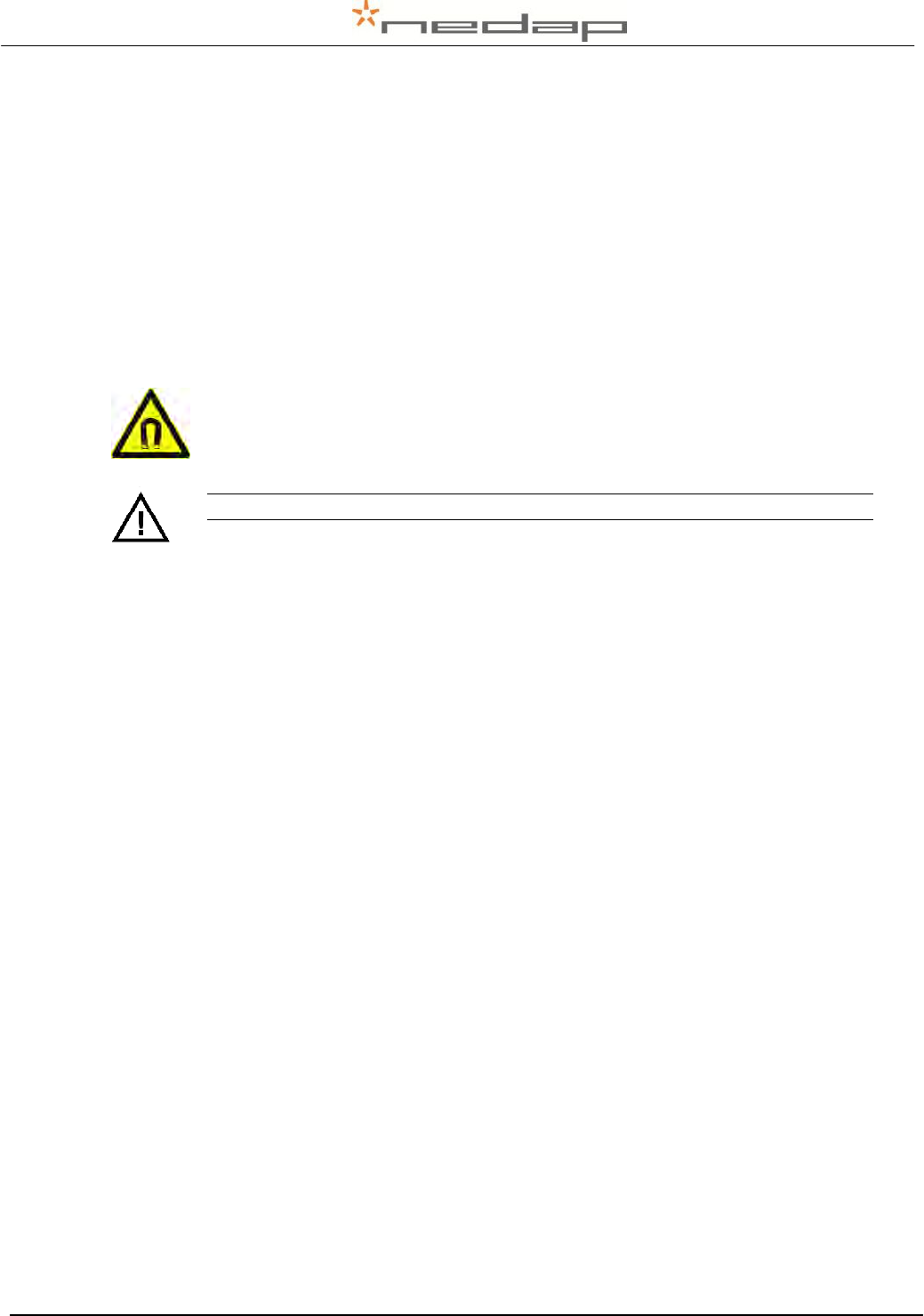
Danger due to electromagnetic fields.
People with pacemakers, metallic implants or hearing aids may experience
complications. Such people should consult their doctor before entering a site with
inverters.
Make sure all safety warnings remain visible.
3.2. Safety precautions during installation
Always turn off the main power when working on the electrical installation.
The installation area must be free from any obstacles, including animals.
When installing, carefully follow the instructions in this manual step by step.
Make sure all items are installed out of reach of animals.
3.3. Animal welfare and safety
The automated actions of the Nedap Velos Livestock Management System do never discharge
the user of the system from his/her responsibility to assure and to take care of the well-being of
the animals.
Nedap Velos – RealTime Heat detection service manual GB Manual version 1.6 / Page 4
4. Installation
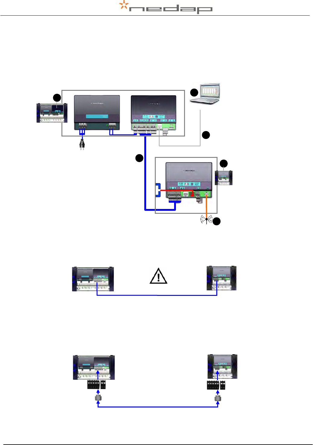
See chapter 4 and 5 for the installation of one antenna. For installing more than one antenna
see also Appendix F. See chapter 3.1 for safety precautions during installation and Appendix A
for technical specifications.
Figure 5. Overview Heat detection system items with numbers range of order of installation
4.1. Mounting the V-box 1 and the V-box 2 on the wall
Mount the V-box 1 (with the antenna reader) and the V-box 2 (process unit with the power
supply and the VPU controller) on a wall. Pay attention to the maximum cable length. See
Appendix E for more information about mounting the V-boxes.
The maximum distance between the VPU and the VP4101 is 200 meter.
Figure 6. Maximum cable length
4.2. Mounting the antenna
Mount the antenna firmly on a bar. Use the supplied mounting brackets, bolts and nuts. Keep
enough distance from the floor, the walls and the ceiling.
Figure 7. Mounting the antenna on a horizontal or vertical bar with two mounting brackets
2.5 – 4 m.
> 1 m.
> 0.3 m.
2.5 – 4 m.
3
L
e
n
gt
h
of
c
or
ri
d
or
(
m
)
2
1
L
e
n
gt
h
of
c
or
ri
d
or
(
m
)
5
1
L
e
n
gt
h
of
c
or
ri
d
or
(
m
)
6
1
L
e
n
gt
h
of
c
or
ri
d
or
(
m
)
4
1
L
e
n
gt
h
of
c
or
ri
d
or
(
m
)
1
L
e
n
gt
h
of
c
or
ri
d
or
(
m
)
← 2 m. →
← < 200 m. →
↑
2 m.
↓
8
L
e
n
gt
h
of
c
or
ri
d
or
(
m
)
7
L
e
n
gt
h
of
c
or
ri
d
or
(
m
)
Process
unit
← Max. 200 m. →
VP4101
Nedap Velos – RealTime Heat detection service manual GB Manual version 1.6 / Page 5
5. Starting up operation
5.1. Connecting the process unit
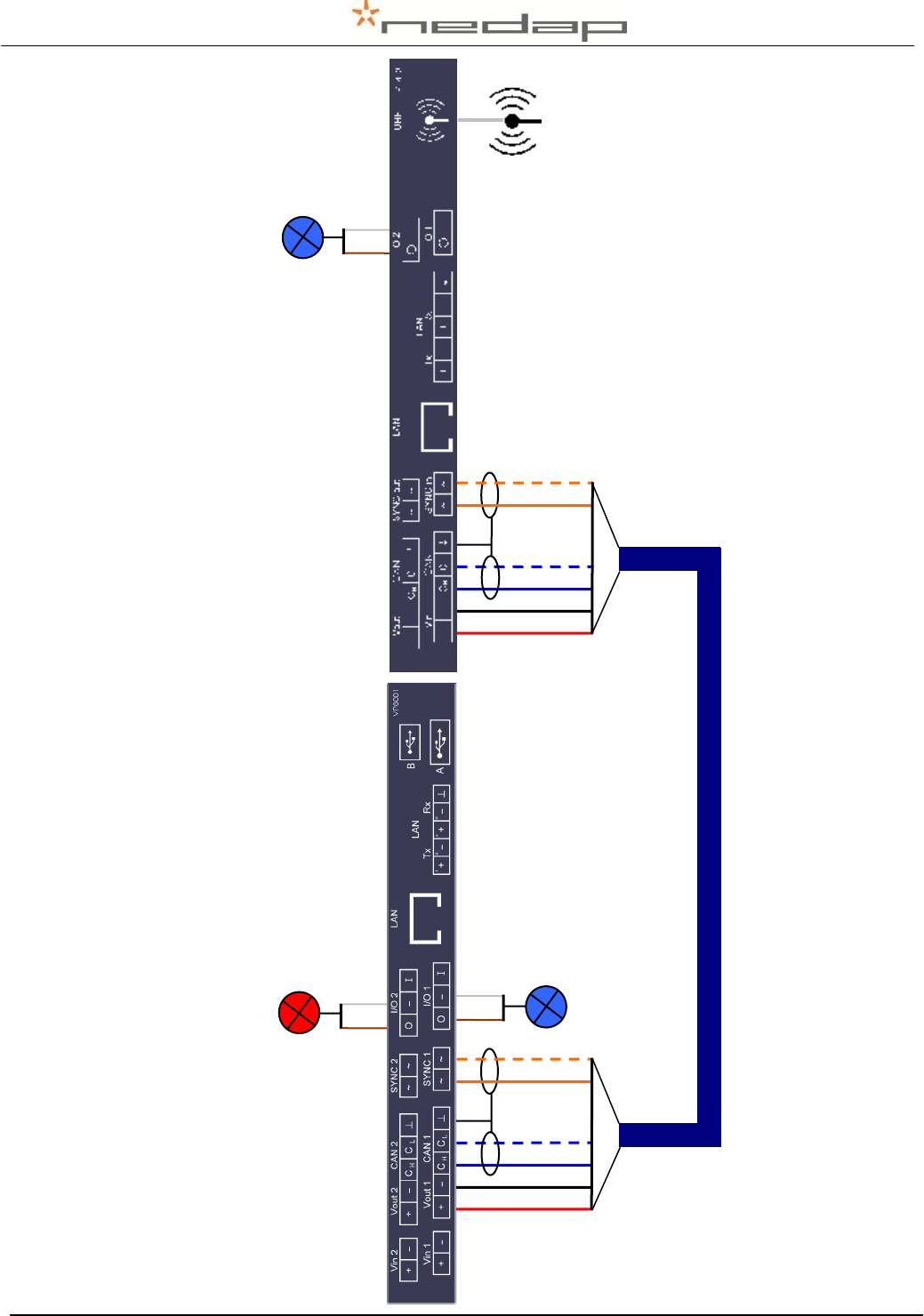
Connect the VPU controller to the VP4101 antenna reader and to a PC.
1. VPU controller
(VP8001) in process
unit
2. VP4101 reader
3. Antenna
4. Network or PC
5. Communication cable
6. UTP cat5 cable
Figure 8. Overview process unit connected to one or more VP4101 readers
1. Prepare the length of the blue communication cable for the distance between the VPU and
the VP4101. Pay attention to the maximum cable length of 200 meter
Figure 9. Maximum cable length
2. Take the connectors from the VPU controller and the VP4101 reader that need to be wired.
Put the communication cables through the cable glands, connect the communication cable
to the connectors and plug the connectors in the VPU controller and the VP4101. See the
next page for a detailed wiring scheme for the cable between the VPU and the VP4101.
Figure 10. Connecting the VPU and the reader
Process
unit
← Max. 200 m. →
VP4101
Process
unit
VP4101
Comm. cable
VPU
VPU
VPU
VP4101
To PC
6
L
e
n
gt
h
of
c
or
ri
d
or
(
m
)
1
1
L
e
n
gt
h
of
c
or
ri
d
or
(
m
)
4
L
e
n
gt
h
of
c
or
ri
d
or
(
m
)
5
L
e
n
gt
h
of
c
or
ri
d
or
(
m
)
2
L
e
n
gt
h
of
c
or
ri
d
or
(
m
)
3
1
L
e
n
gt
h
of
c
or
ri
d
or
(
m
)
Nedap Velos – RealTime Heat detection service manual GB Manual version 1.6 / Page 6
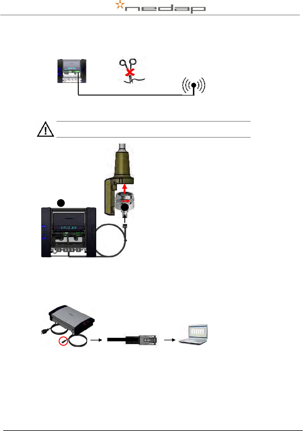
The default position of the red heat
detection attention light is on the
VP8001 (VPU) as shown. The red
light can optionally be connected to
O 1 on the VP4101.
Heat detection wiring communication cable from VPU (VP8001) to the first VP4101
white
Feed 2
brown
Feed 2
white
Feed 2
brown
Feed 2
white
Feed 2
brown
Feed 2
VP8001
VP4101
blue white
Feed 2
red
Feed 2
black
Feed 2
orange
Feed 2
blue
Feed 2
orange white
Feed 2
Comm. cable
IN
Comm. cable
OUT
blue white
Feed 2
red
Feed 2
black
Feed 2
orange
Feed 2
blue
Feed 2
orange white
Feed 2
Nedap Velos – RealTime Heat detection service manual GB Manual version 1.6 / Page 7
5.2. Connecting the antenna
Connect the antenna to the VP4101 reader.
Figure 11. Distance between reader and antenna
Do NOT shorten or lengthen the cable. The antenna cable length must
stay 2.5 meters.
1. V-box 1 housing with
VP4101 Reader
2. Antenna cable
Figure 12. Antenna connection to VP4101
5.3. Connecting the PC or network
Connect the process unit UTP cat5 cable to a network or PC.
Figure 13. Connecting the process unit to a PC or network
Antenna
← 2 m. →
Reader
VP4101
2
L
e
n
gt
h
of
c
or
ri
d
or
(
m
)
1
L
e
n
gt
h
of
c
or
ri
d
or
(
m
)
VP4101
Nedap Velos – RealTime Heat detection service manual GB Manual version 1.6 / Page 8
5.4. Connecting the power
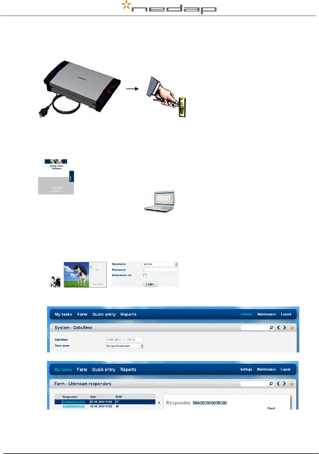
Connect the Process unit power supply (VP2002) plug to a main electricity source.
Figure 14. Connecting the power
5.5. Setting up the VPU network configuration
To set up the network configuration make sure the VPU is operational and
connected to the network. Take the VPU Setup CD and run it on the connected
PC to set the IP address correctly automatically. See Appendix H for more
information about this.
5.6. Setting up the VPU software
The VPU software is pre-installed. Start up the VPU program to adjust some general program
settings.
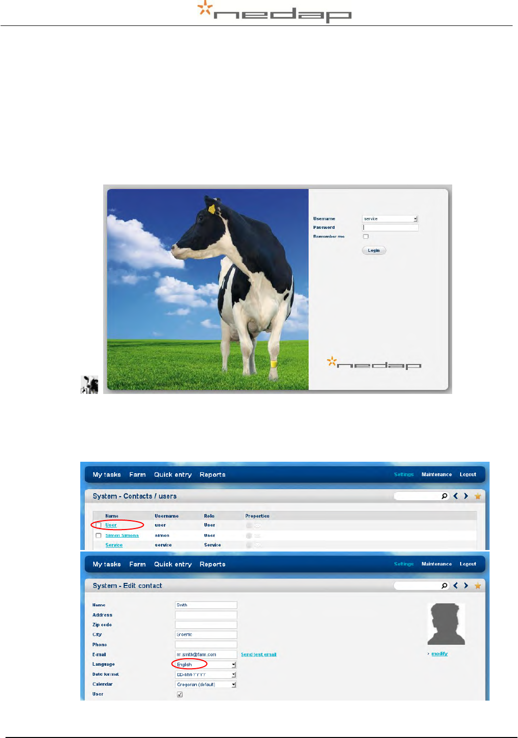
1. Click on the VPU program shortcut on the desktop to start the program on the VPU
controller. Enter the service password in the login page and press login. The default
service password is service and the default user password is 1234.
service password = service
2. Check the date (format) and time (zone) in the page Settings >System – Date/time. The
VPU will restart after adjustment. Press Submit to save the changes.
From now on the antenna will function.
The responder number identified at the antenna and the signal strength at the detecting
location will now be shown in the page My tasks > Farm – Unknown responders-realtime.
Nedap Velos – RealTime Heat detection service manual GB Manual version 1.6 / Page 9
6. Start up operation VPU program
Enter the animal and responder numbers and the heat detection settings.
6.1. First settings
Enter the password and make the first settings.
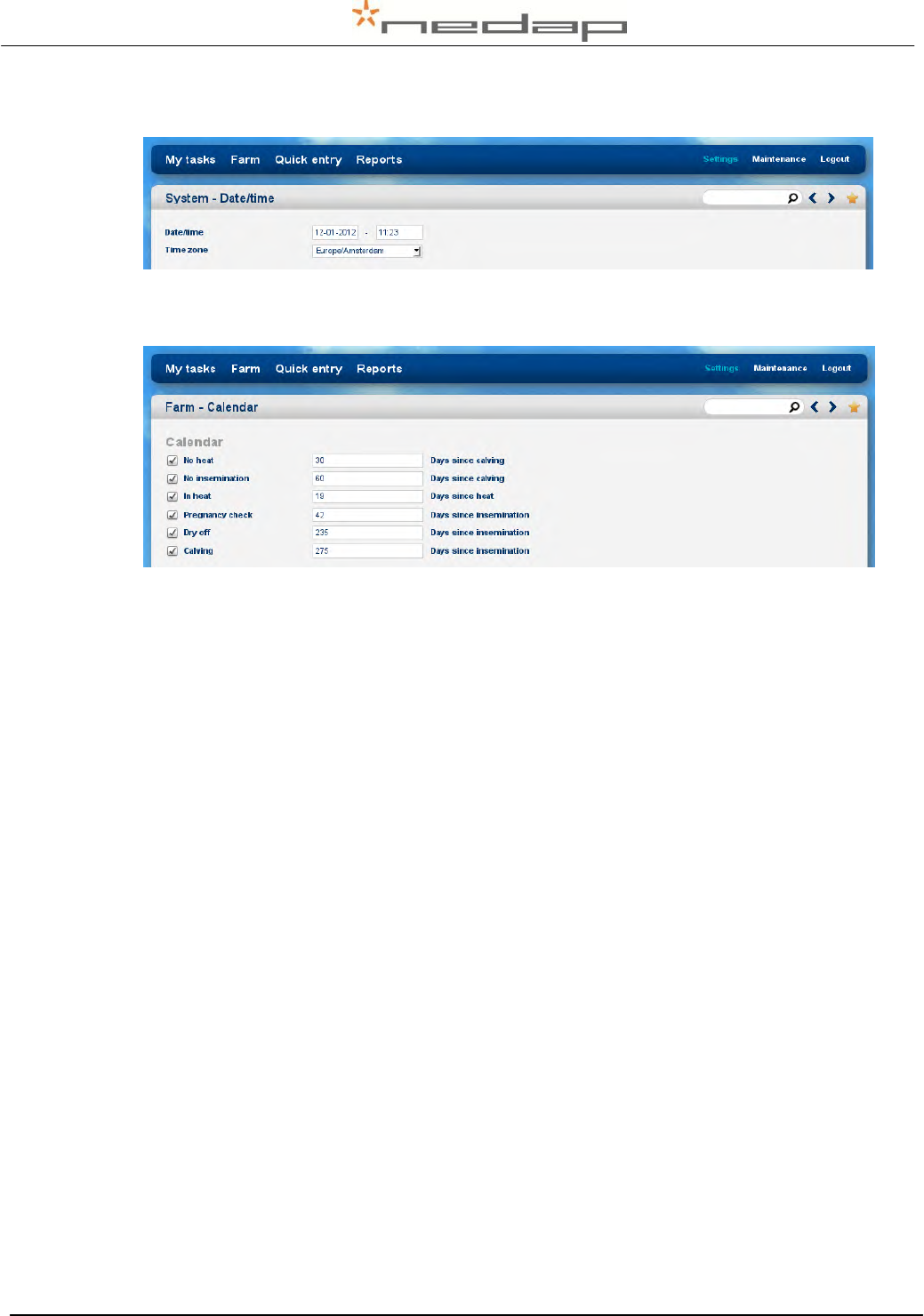
1. Click on the VPU program shortcut on the desktop to start the program on the VPU
controller. Enter the user password in the login page and press Login. The default User
password is 1234.
2. Enter a unique user password in the English page Settings >System – Users. Click on the
left hand side of the page on Settings and then on Users (under the System heading). Click
on User to change the default password in a new password and to change the language
from English to another language. Optionally add more users.
Nedap Velos – RealTime Heat detection service manual GB Manual version 1.6 / Page 10
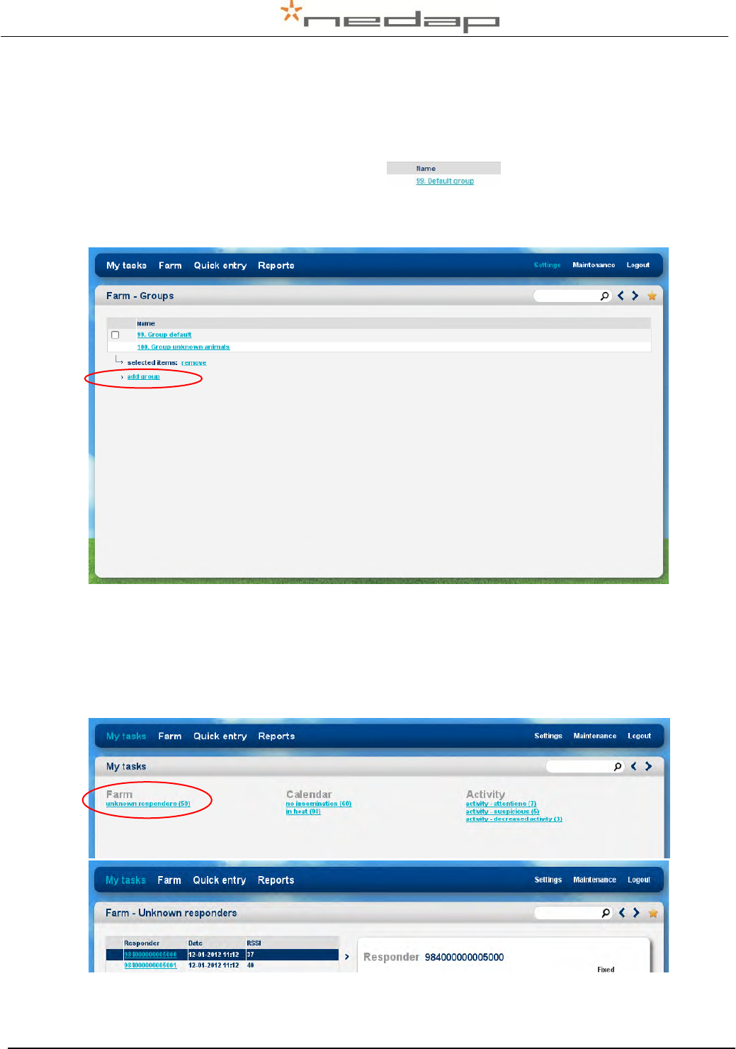
3. Check the date and time (zone) in the page Settings >System – Date/time. The VPU will
restart after adjustment. Press Submit to save the changes.
4. Optionally adjust the calendar attention settings in the page Settings > Farm – Calendar.
See chapter 7.4, 7.5 and 7.6 for more information about the calendar.
Nedap Velos – RealTime Heat detection service manual GB Manual version 1.6 / Page 11
6.2. Entering new animal numbers (and groups)
6.2.1. Entering new groups
There is one default group: group number 99.
Optionally add one or more new group(s) in the page Settings > Farm - Groups to be able to put
animals in different groups.
6.2.2. Entering new animal numbers in the system
Add the animal numbers and the other animal data in the VPU program after the responders
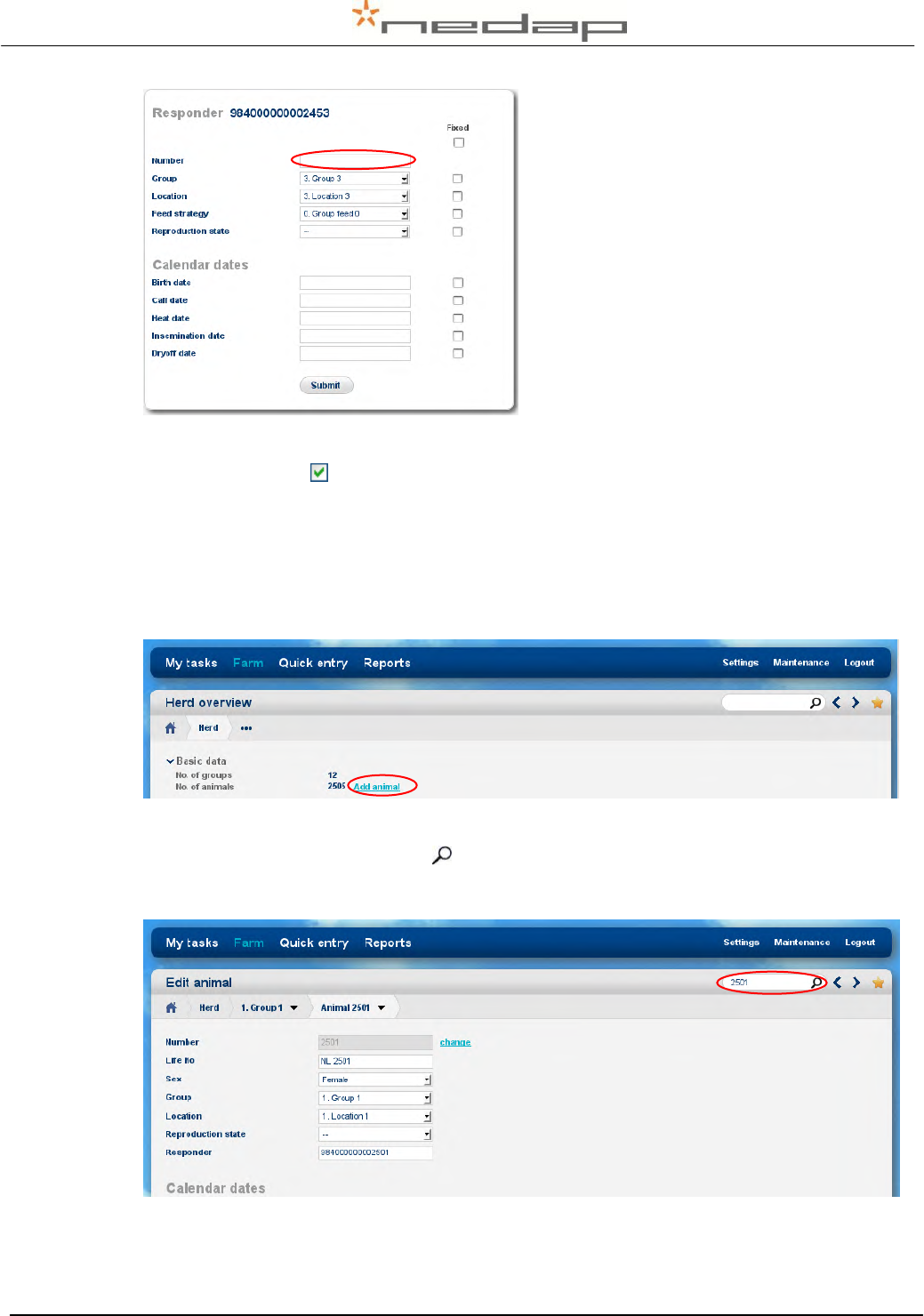
from the animals were identified at an antenna.The responder number of animals with a motion
sensor, identified at the antenna for the first time, will appear in the page My tasks > Farm –
Unknown responders.
Click on a responder number to enter the animal number from this sensor in the program.
Nedap Velos – RealTime Heat detection service manual GB Manual version 1.6 / Page 12
Enter the animal number from the animals with the unknown responder numbers and
optionally adjust the group number and the other data. Click on Submit to store the data.
Use the option Fixed to keep this same value for the data of the next motion sensor.
6.2.3. Changing the responder number and/or basic data
Adding a responder number and data from new animals manually is possible in the page
Farm > Herd or Group overview (see screenshot below) but not advisable. It is easier to
identify the responder number at the antenna first and enter the animal data via the
Unknown responder page (see description above).
To change the responder number or to add or change other basic data after an animal was
entered for the first time, select the link Basic data in the page Farm > Animal (enter the
number behind the magnifying glass at the bottom of the page an press enter). The
responder number can not be changed when using synchronisation with a Nedap server
(see Appendix I for more information about this).
Enter the heat dates and calving dates in this page later on also or use the Quick entry
page.
Nedap Velos – RealTime Heat detection service manual GB Manual version 1.6 / Page 13
6.3. Heat detection attention settings
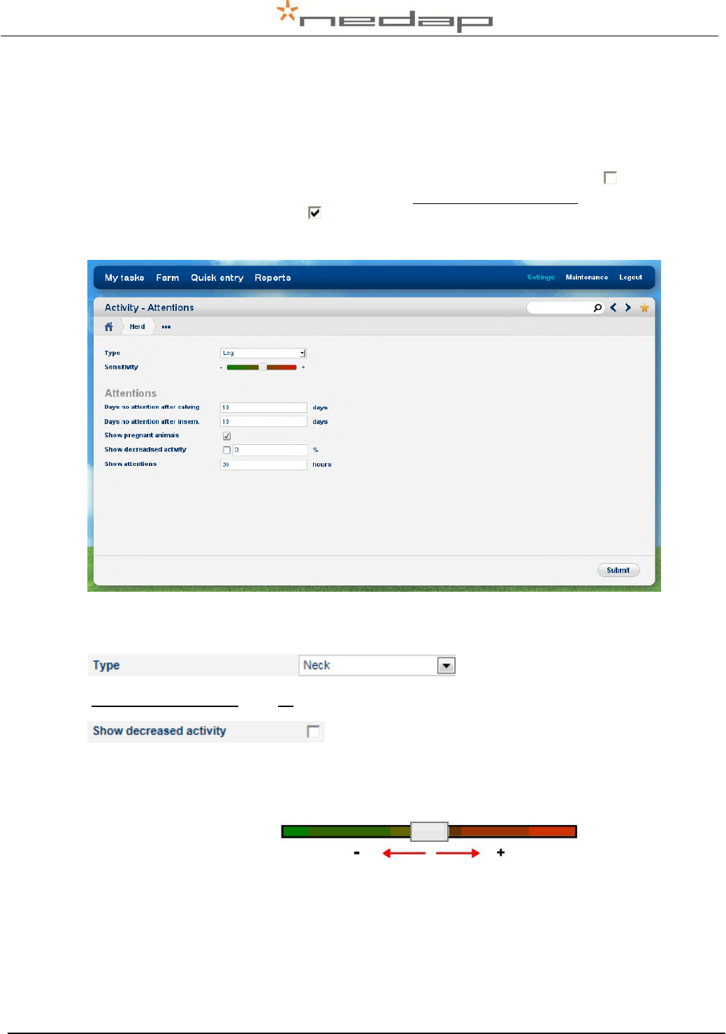
Optionally adjust the activity settings in the page Settings > Activity - Attentions. The first days
after calving and insemination NO attentions will be given because the averages are not reliable
yet. This first period of no attentions will only work if the calving date and the last insemination
date of an animal is always entered. Turn off the Show pregnant animals check box to ignore
the activity attentions of animals with state pregnant. In case of leg sensors only: turn on the
Show decreased activity check box to see the animals with a decreased activity attention. The
activity attentions will disappear after the Show attentions set hours. Press Submit to save any
changes.
Enter the type of sensor (Leg or Neck) used. In case of both neck and leg sensors on one farm,
create separate groups for the different types of sensors.
In case of neck sensors: turn off the field Show decreased activity.
Adjust the sensitivity of the activity attentions if necessary. Animals will get an attention when the
activity is higher than the level set for several following 2-hour periods. In case of a lower
sensitivity less animals will get an attention.
Less attentions More attentions

Nedap Velos – RealTime Heat detection service manual GB Manual version 1.6 / Page 14
6.4. Eating monitor attention settings (neck sensors only)
Adjust the threshold (default 20%) of the eating monitor attention settings if necessary in the
page Settings > Eating monitoring - Attentions. Animals will get an attention when the feed
eating time is lower than the average level of this animal of the past 10 days.
Nedap Velos – RealTime Heat detection service manual GB Manual version 1.6 / Page 15
7. Operation VPU program
7.1. Viewing animals in heat
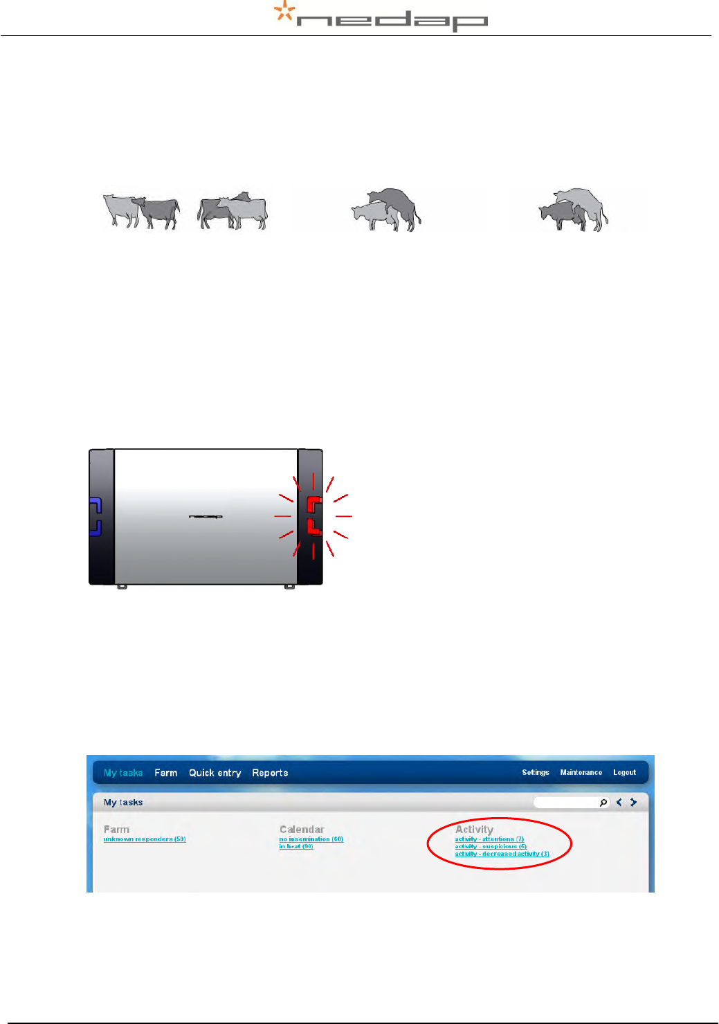
The behaviour of an animal in heat is quite different from her normal behaviour. She is restless,
tries to mount other animals, gets mounted by other animals and shows a standing reflex.
sniffing, chin resting / ± 12 hours
mounting other cows (attempt) / ± 8 hours
standing heat / ± 5 hours
The antenna will often receive the activity information and the animal responder number from
every RT motion sensor in the antenna field. The antenna reader collects these data and sends
them to the Velos program every 2 hours. An animal does not need to be in the antenna field all
the time, at least once every 24 hours is the minimum to store the complete 24 hour activity data
but more frequent readings is necessary for accurate attentions.
The activity measurement monitors the changes in the active behaviour of the individual animals
because the activity in a period is compared to the activity in the same period on the previous
days. An activity attention is generated if necessary. The program displays overviews of animals
with an activity attention on a PC screen or on a mobile phone.
The red attention light of the process unit will warn
if there is an activity attention.
There are 2 types of activity attentions: Activity attention animals that are most likely in heat
and Suspicious animals that may be in heat but do not have an attention (yet).
Highly increased activity
Suspicious
Attention
Nr. of following 2-hour periods
2
3 or more
In Heat
Maybe
Probably
View animals with an activity attention in the page My tasks > Activity - attentions. View
suspicious animals in the page My tasks > Activity - suspicious.
View animals with a decreased 24h activity in the page My tasks > Activity - decreased activity.
Optionally check other data from these animals (e.g. decreased activity details, milk yield and
feed balance) and check the animals for e.g. lameness if necessary.
Nedap Velos – RealTime Heat detection service manual GB Manual version 1.6 / Page 16
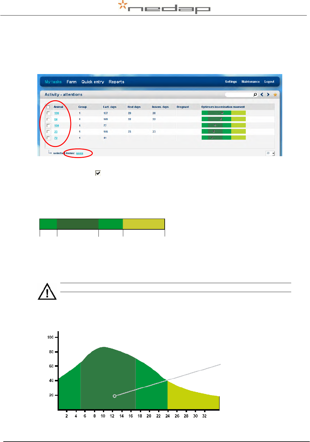
Check animals with a clear activity attention in the page My Tasks > Activity – attentions. Check
the optimum insemination moment, the number of days in lactation, the number of days since
the last heat and the number of days since the last insemination. The dark green colour in the
coloured bar indicates the optimum insemination moment.
Click on an animal number to view the activity details from the past days.
Tick off the checkbox for the attention animals that were seen or checked and press Seen to
mark them as seen on the attention list. The red attention light of the process unit will now be off.
The green coloured bar is shown for animals with an activity attention. The dark green optimum
insemination moment is based on the first attention. The real ovulation moment will vary per
animal, breed and herd.
An insemination should occur 5 – 17 hours after the first activity attention or 0 – 12 hours after
the first standing heat.
Inseminate directly after the first activity attention or the first standing heat.
It may generally be assumed that, if an animal is actually in heat, she should be inseminated
directly after the first activity attention. This gives the best chance of conception as the injected
sperm cells are then able to reach the egg at the optimum moment.
Optimum insemination
moment
0 5 17 24 36 h
0 = first 2h period attention for a clear increased activity
Duration of heat in hours
Probability of conception (in %)
Feed 5*
Nedap Velos – RealTime Heat detection service manual GB Manual version 1.6 / Page 17
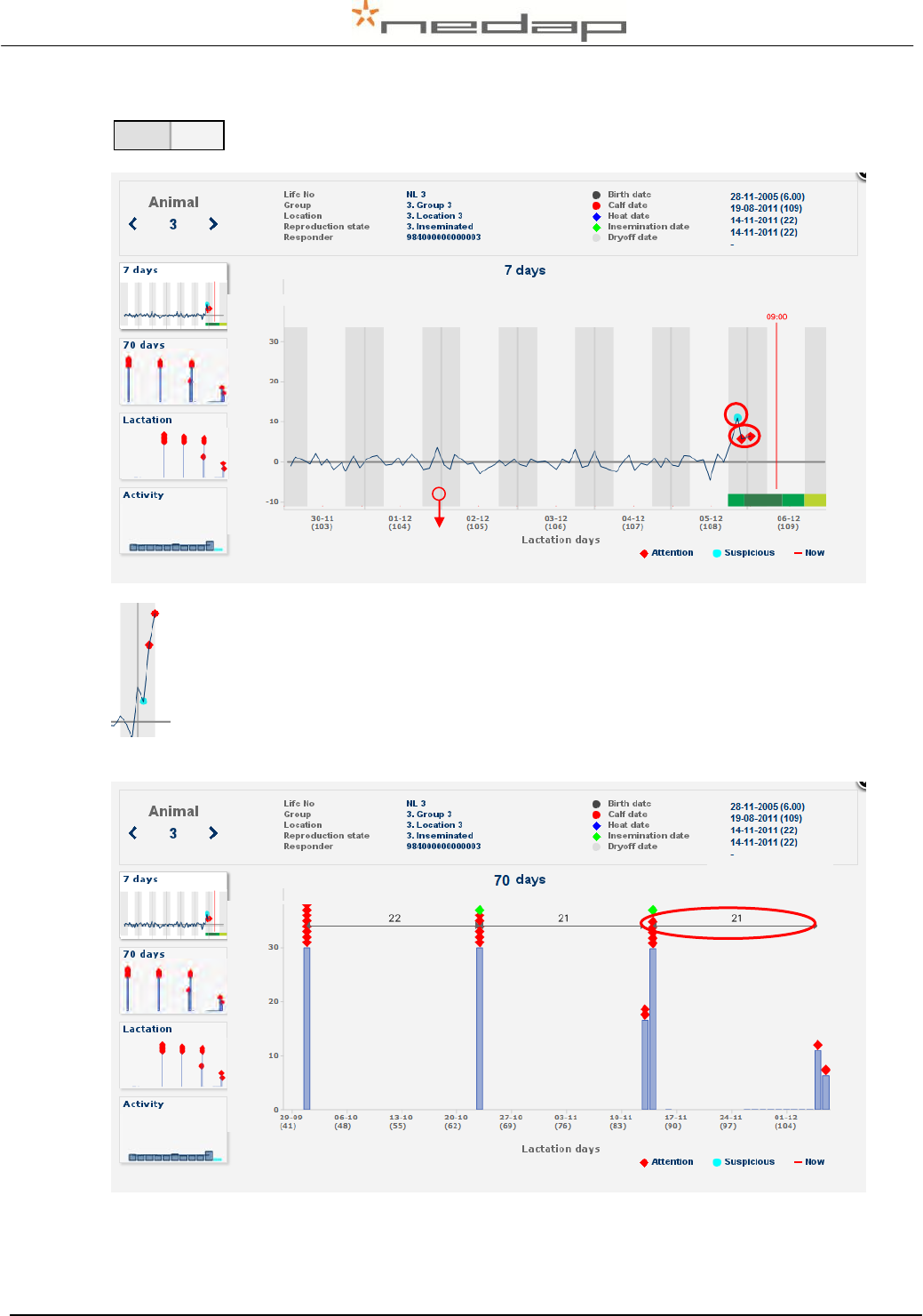
View the animal activity details from the past days (light column with noon in the
centre) and nights (dark column with midnight in the centre). The diamonds in
the activity line indicate the activity attentions.
A light blue dot ● is a suspicious high 4 hour activity and a red colour diamond ♦ is a
clear 6 hour activity attention. The activity line shows the measured activity compared
to the activity in the same period on the previous days.
Select the 70 day graph to view the interval since last activity attention(s) (e.g. 21 day heat
cycle).
Put the mouse cursor on ● ● ♦ ♦ to view the exact calendar date entered by the farmer.
Night Day
Midnight

Nedap Velos – RealTime Heat detection service manual GB Manual version 1.6 / Page 18
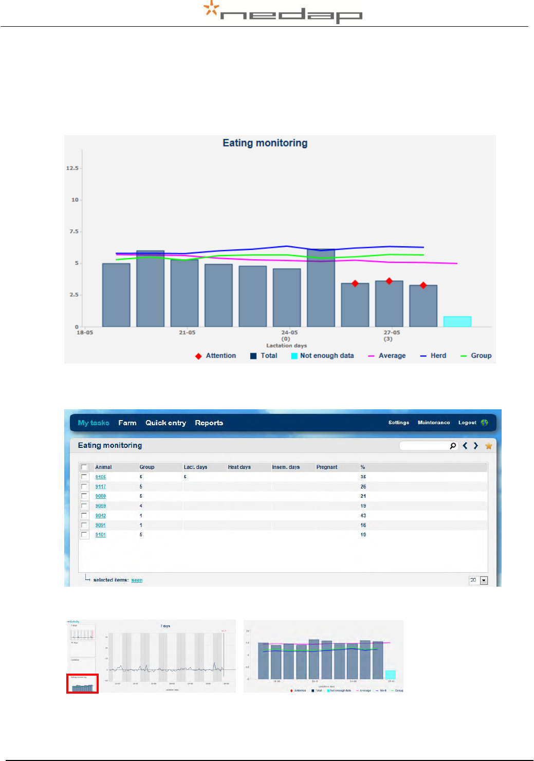
It is also possible to view animals with an activity attention in the Heat detection attentions report
in the page Reports > Activity - attentions.
Nedap Velos – RealTime Heat detection service manual GB Manual version 1.6 / Page 19
7.2. Viewing eating monitor attentions (neck sensors only)
The eating monitor registers the changes in the eating behaviour of the individual animals
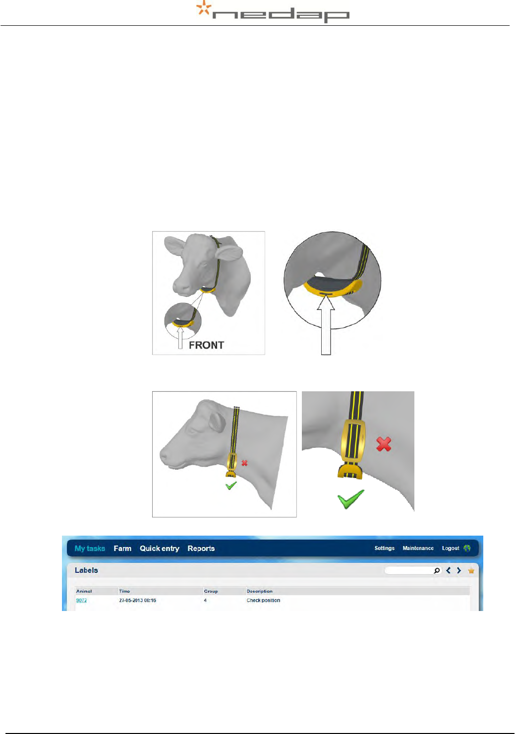
because the eating time of the past day is compared to the eating time of the previous days. An
eating monitor attention is based on the data from the past day and it is valid for 24 hours.
View animals with an eating monitor attention in the page My tasks > Eating monitor - Attentions.
The % shows how much percent the eating time has decreased.
Click on an animal number and then on the eating monitor graph to view the monitor details.
The last day is the current day. This graph increases during the day. It has a blue colour
because there are not enough data to be used as a reference. The average of the herd and the
group is shown to compare to.
Example of eating monitoring attention after calving
Example % > 15 % decreased eating time
Nedap Velos – RealTime Heat detection service manual GB Manual version 1.6 / Page 20
7.3. Viewing label attentions (neck sensors only)
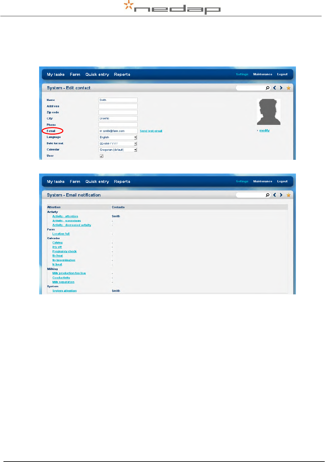
The label can only monitor the behaviour of the animals if the label is on the cows neck in the
right position. The label attentions are used to detect labels that are in a wrong position on the
neck or turned sideways on the neck.
Check the labels of animals with a label attention as shown in the page My tasks > Labels –
Attentions. Put the label on the neck in the correct position.
The label can be attached backwards or the label can be in a wrong position.
Back to front
Label attached backwards, the groove (and the arrow on the back of the label) is
pointing towards the cows body instead of the cows head.
Check position
Label in a wrong position. Turned sideways on the neck or twisted on the collar.
If a label position is incorrect, it can take up to a day for the attention to appear. If a label is put
back in the correct position, it can take up to a day for the attention to disappear.
Groove towards head cow = OK
Nedap Velos – RealTime Heat detection service manual GB Manual version 1.6 / Page 21
7.4. Using e-mail notification
Enter the e-mail address in the page Settings > System – contact/users (edit contact).
Enter what type of attentions should be send in the page Settings > System – email notification.
7.5. Using a mobile phone with Internet connection
The Velos mobile program is available in the Heat detection system. It can display an overview
of animals with an activity attention on a mobile phone. See Appendix G for more information.
Nedap Velos – RealTime Heat detection service manual GB Manual version 1.6 / Page 22
7.6. Setting up the calendar attentions
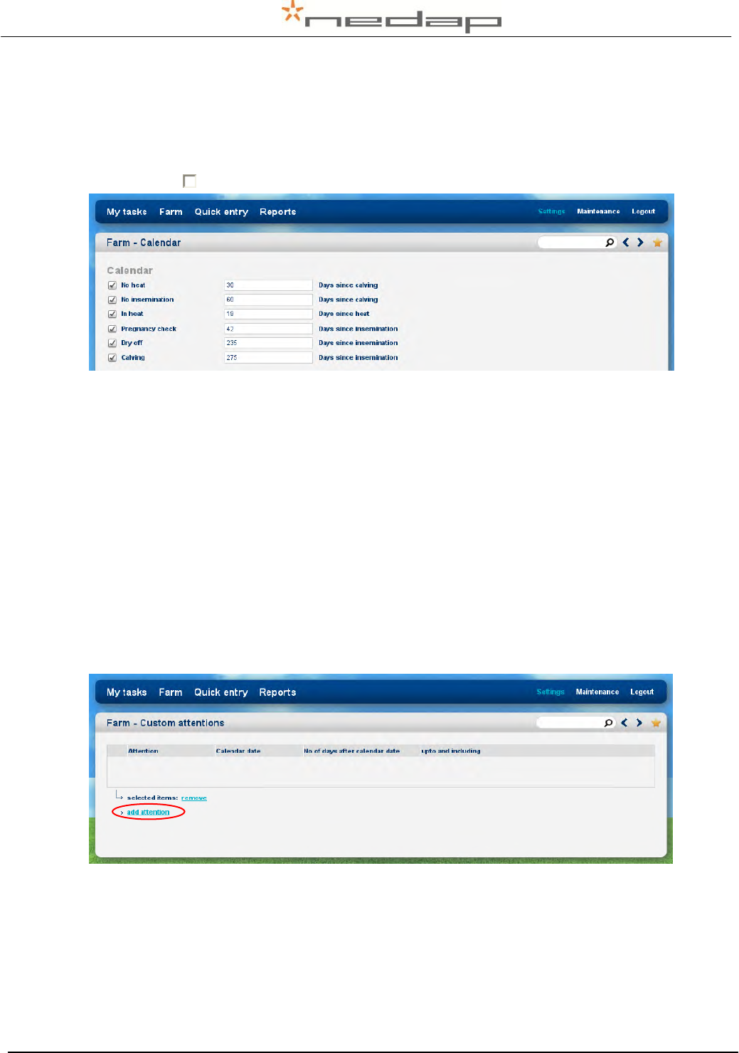
1. Optionally adjust the calendar attention settings in the page Settings > Farm – Calendar. A
calendar attention will be given a certain number of days after a calendar event (a calving,
heat or insemination). Optionally adjust the number of days of a first attention or switch off a
check box to turn off an attention.
Attention
BEGIN
Days since
+ Reprod. State
-
END
No Heat
30 - 60
Calving
Open
-
Ins date + state Ins.
No Insemination
≥ 60
Calving
Open
-
Ins date + state Ins.
In Heat*
19 -23
Heat or Insem.
Open/Insemination
-
State pregnant
Pregnancy check
≥ 42
Insemination
Insemination
-
State pregnant
Dry off
235 - 275
Insemination
Pregnant
-
Dry off date
Calving
≥ 275
Insemination
Pregnant
-
Calving date
* The In Heat attention will be given for five days and for five 21 day cycles starting on the set
number of days after the last heat or insemination.
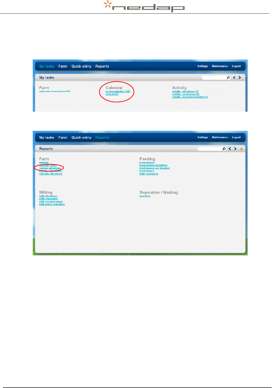
2. Optionally create one or more additional new calendar attentions in the page Settings >
Farm - Custom attentions. Such custom attentions can be given a certain number of days
after a calendar event (a birth, calving, heat, insemination or dry off date).
Click on Add attention to enter one or more custom attentions.
A few examples:
Custom attention
BEGIN
-
END
Days since
Insemination yearling
395
-
500
Birth date
Separate for calving
265
-
275
Insemination date
Colostrum
0
-
5
Calving date
Nedap Velos – RealTime Heat detection service manual GB Manual version 1.6 / Page 23
7.7. Viewing calendar attentions
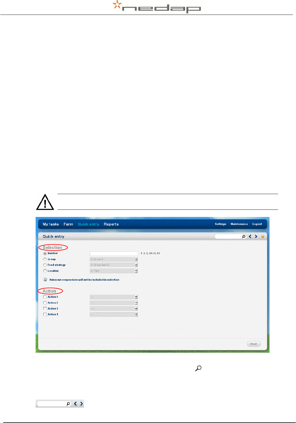
1. View the calendar attentions in the page My tasks > Calendar. Click on a type of calendar
attention to view the animals with an attention and click on an animal number to view the
basic animal data.
2. View the custom attentions in the page Reports > Farm – Custom attentions e.g the
Separate for calving report.
Nedap Velos – RealTime Heat detection service manual GB Manual version 1.6 / Page 24
7.8. Entering calendar data
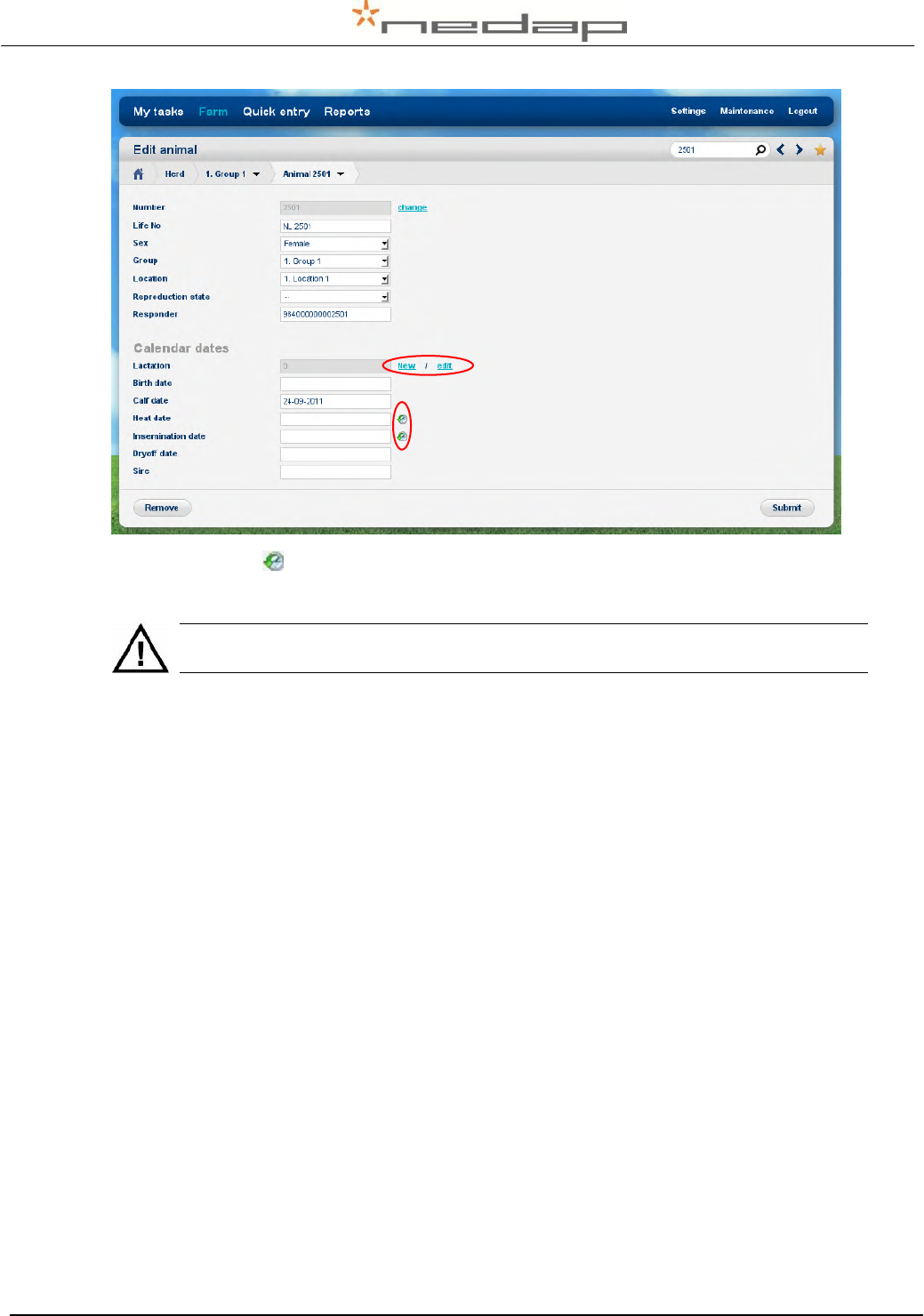
Enter new calendar events in the page Quick Entry or in the page Farm > Edit animal and adjust
the reproduction status if necessary.
Event
Enter calendar data
Adjust reproduction state
Calving today
New lactation (= calving date today)
- (automatically adjusted to Open)
Calving before
New lactation + correct calving date
- (automatically adjusted to Open)
Heat
Heat date
-
Insemination
Insemination date (+ Sire data)
Insemination
Pregnancy check
-
Pregnant
Dry off
Dry off date
-
Keep Open
-
Keep Open
Birth
Birth date
-
Method 1 to enter calendar data is via the page Quick Entry. Enter the Animal number(s) under
Selection and select an action (e.g. an calendar date or reproduction state).
When a new lactation is started all totals and calendar data from the previous lactation
will be deleted.
Method 2 to enter calendar data is in the page Farm > Edit animal via the page Farm > Animal
overview. Enter an animal number behind the magnifying glass at the bottom of the page or
click on an animal number in the page My tasks > Calendar to view the Basic data in the page
Farm > Animal overview. Select the link Basic data in this page to view more details or to enter
calendar data.
Nedap Velos – RealTime Heat detection service manual GB Manual version 1.6 / Page 25
Click on the image behind the heat or insemination date to view the previous heat and
insemination dates. Click on New to start a new lactation with the calving date today.
When a new lactation is started all totals and calendar data from the previous lactation
will be deleted.

Nedap Velos – RealTime Heat detection service manual GB Manual version 1.6 / Page 26
8. Maintenance
Check the operation of the antennas regularly by testing the identification with a motion sensor
that is not used on an animal and by checking the registered activity data.
Carry out maintenance of the antennas according to the table below.
Item to check
After 1st
week
Every
week
Every
month
Every 6
months
What/How to check
Motion sensors
X
Check the attachment at
the animal’s leg.

Nedap Velos – RealTime Heat detection service manual GB Manual version 1.6 / Page 27
9. Malfunctions
The webpage My tasks > System - System attentions will show if there are any malfunctions.
If the system is not working correctly, an alarm will occur. The blue light on the VPU will blink.
Check the cause of the alarm, solve it and remove the alarm.
Problem with
What/How to check or re-install
See §
The hardware components
See manual chapter 4 Assembling.
Ch. 4
The wiring and connections
See manual chapter 5 Starting up operation. Turn off
the power before starting wiring.
Ch. 5
The V-pack addresses
See manual Appendix C Setting the VP4101 address.
App. C
The network configuration
See manual chapter 5.5 Setting up the VPU network
configuration and Appendix H.
§ 5.5
The VPU software
See manual chapter 5.7 Setting up the VPU software.
§ 5.7
Mobile access
See manual Appendix G Mobile access
App. G

Nedap Velos – RealTime Heat detection service manual GB Manual version 1.6 / Page 28
10. Disposal
At discard dispose of materials from the Heat detection system in accordance with the current
environmental rules of the state or local governing authorities.

Nedap Velos – RealTime Heat detection service manual GB Manual version 1.6 / Page 29
Appendix A Technical specifications
Specifications for transport / installation
Electrical supply
Main supply
100V - 240V
Frequency
50 – 60 Hz
Input voltage (use Nedap power supply)
24-28V DC
Environmental
Operating temperatures
0°C / +45°C
Transport / storage temperatures
-25°C / +70°C
Humidity (rh)
45°C / 85%
Enclosure protection class (when cover and cables installed correctly)
IP65
Enclosures of electronics may not be exposed to direct sunlight.
The identification of the Nedap Velos system is compatible with the ISO standard (ISO 11784
and 11785).
Check if electronic equipment from manufacturers other than Nedap is used on the
farm. If the other system is not compatible to the ISO system this can have a negative
influence on the ID performance of the Nedap Velos system. Please contact your
Nedap Velos dealer.
Nedap Velos – RealTime Heat detection service manual GB Manual version 1.6 / Page 30
Appendix B Restore factory defaults
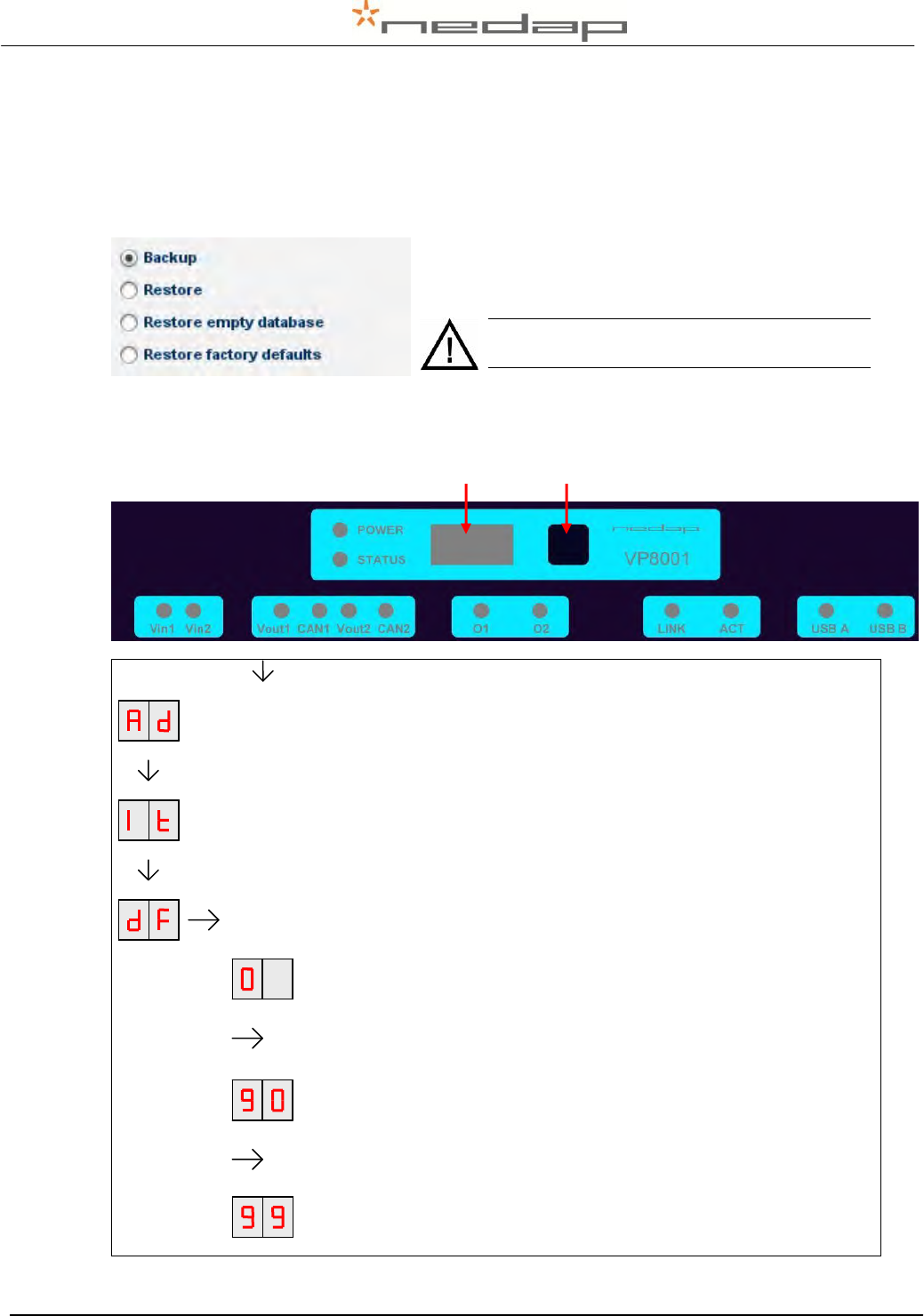
The default VPU (VP8001) address is 01. Restore the VPU factory defaults if necessary in the
page Maintenance > System – Backup/Restore or in the VPU (VP8001) V-pack menu.
Method 1.
Choose Restore factory defaults in the page
Maintenance > System – Backup/Restore.
Method 2.
Enter dF value 99 in the VPU (VP8001) V-pack display menu.
Press button short to start menu.
Press button short.
Press button short.
Press button long to start menu
Press button 9 times short to change the first digit from 0 to 9.
Press button long until blinking to save the first 9 and go to the second
digit.
Press button 9 times short to change the second digit from 0 to 9.
Press button long until blinking to save the number.
The factory defaults will be restored now.
See chapter 5.6 and 5.7 to set up the VPU network configuration and the VPU software anew.
All information will be lost! This action will
delete all animal data and changed settings.
Display Push button
Nedap Velos – RealTime Heat detection service manual GB Manual version 1.6 / Page 31
Appendix C Setting the VP4101 address
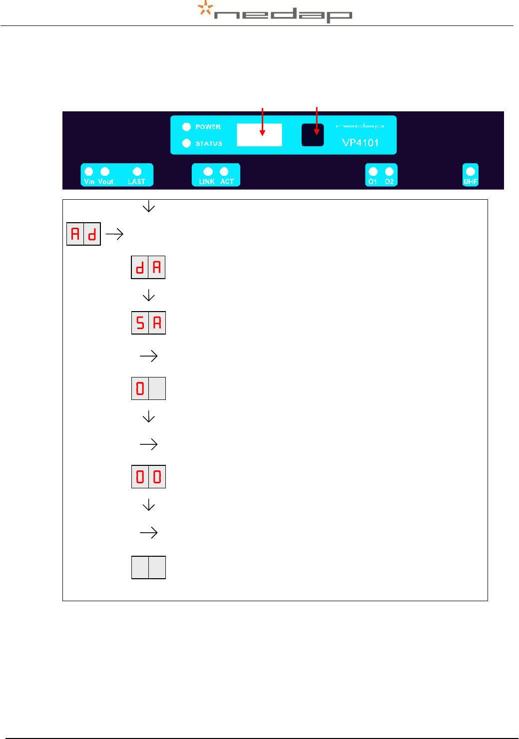
The standard address is 01. In case of more than one antenna use the instructions below to
adjust the VP4101 address.
Press button short to start menu.
Press button long until blinking.
DISPLAY ADDRESS: Shows the actual address when pressed long.
Press button short.
SET ADDRESS: Set the second address to 02 (first address is 01).
Press button long until blinking.
The first digit is showing. The 0 does not always need to be changed.
Option: Press button short to change the number.
Press button long until blinking to move on to the next digit.
The second digit is showing.
Press button short to change the number to e.g. 2.
Press button long until blinking to save the number and go to the next
menu.
To leave menu:
Press button until display is clear.
Display Push button
Nedap Velos – RealTime Heat detection service manual GB Manual version 1.6 / Page 32
Appendix D VP4101 Display
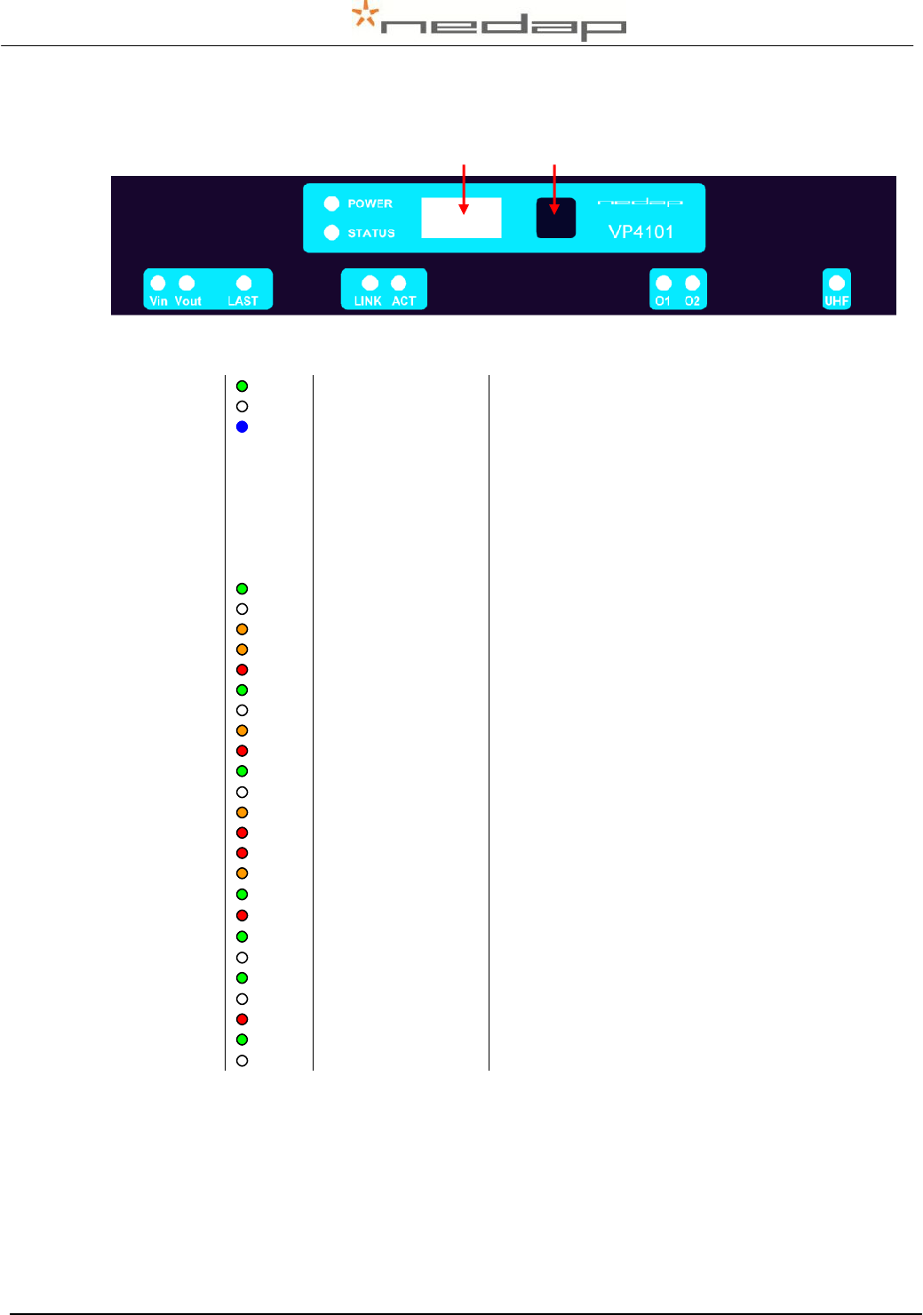
LED indicators
POWER
Green on
Power on
off
No power
STATUS
Blue
Slow blinking
Fast blinking
1 short flash
2 short flashes
3 short flashes
Operating ok
Downloading or error during download
V-pack not connected
Firmware present but not active
No firmware present
Display
on
Address indicated
No communication
off
Communication status ok
V in
Green on
Input power applied
off
No power
Orange
Low power, less than 20V
Orange blinking
Wrong CAN-bus connection, Vin and Vout swapped
Red blinking
Error, plus and minus swapped
V out
Green on
Output power
off
No power
Orange blinking
Low power warning
Red blinking
Error, plus and minus swapped
LAST
Green on
V-pack is last one on the CAN-bus
off
V-pack is not last one on the CAN-bus
Orange blinking
CAN-bus error and last V-pack on CAN-bus
Red
CAN-bus error
Red blinking
CAN-bus warning / connected wrong
LINK
Orange
LAN 100 Mpbs
Green
LAN 10 Mpbs
Red
Error
ACT
Green flashing
Network activity
off
No network activity
O1 / O2
Green on
Output on
off
Output off
Red blinking
Output error
UHF
Green on
Data receive
off
No data
Display Push button
Nedap Velos – RealTime Heat detection service manual GB Manual version 1.6 / Page 33
Appendix E Mounting the V-box
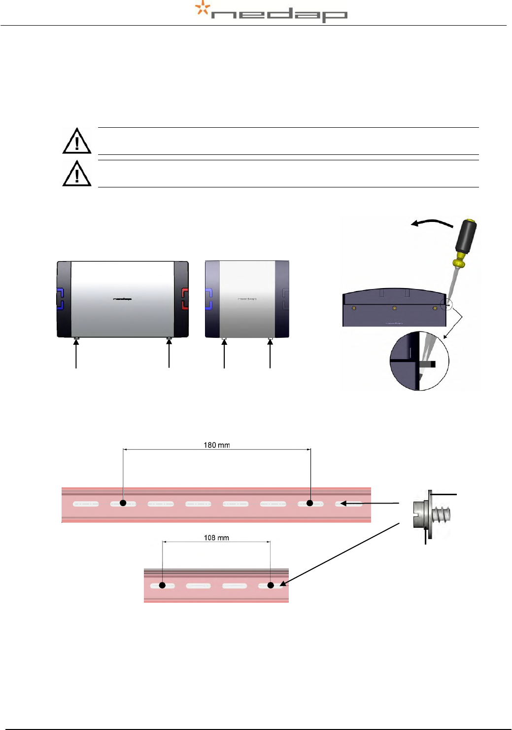
Mount the V-box 1 (with the antenna reader) and the V-box 2 (process unit with the power
supply and the VPU controller) on a wall. In case of two or more antennas mount two or more V-
boxes 1 with an antenna reader. Pay attention to the Maximum cable length.
Mount the process unit not too far from the last VP1001, The maximum cable length
between the VPU controller and the last VP1001 is 80 m. See also figure 11.
Mount the VP1001 close to the antenna, the maximum cable length is 10 m. See also
figure 11.
1. Remove the cover from the V-box.
V-box 2 V-box 1
Figure 15. Opening the V-box
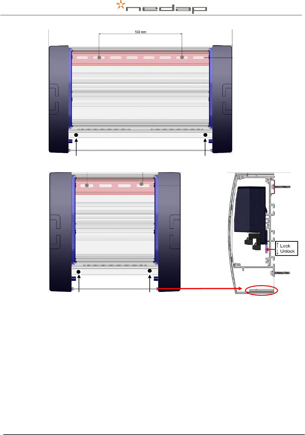
2. Mount the DIN rail on the wall using positions and the distance in the picture below. Use the
supplied plug, screw, plain washer and spring lock washer.
V-box 2
V-box 1
1. Spring lock washer
M5 DIN 127
2. Plain washer M5 DIN
9021
Figure 16. Mounting the DIN rail on the wall with washers on screw detail
3. Put the V-box on the rail. Mount the bottom of the V-box on the wall using the positions in
the picture below. Use the supplied plug, screw, plain washer and spring lock washer.
1
2
Nedap Velos – RealTime Heat detection service manual GB Manual version 1.6 / Page 34
V-box 2
V-box 1
Figure 17. Mounting the V-box
4. Click the V-pack on the rail inside the V-box and lock it.
5. Mount the cable protection sheet at the bottom of the V-box.
6. Close the cover of the V-box.
Nedap Velos – RealTime Heat detection service manual GB Manual version 1.6 / Page 35
Appendix F Installing more than one antenna
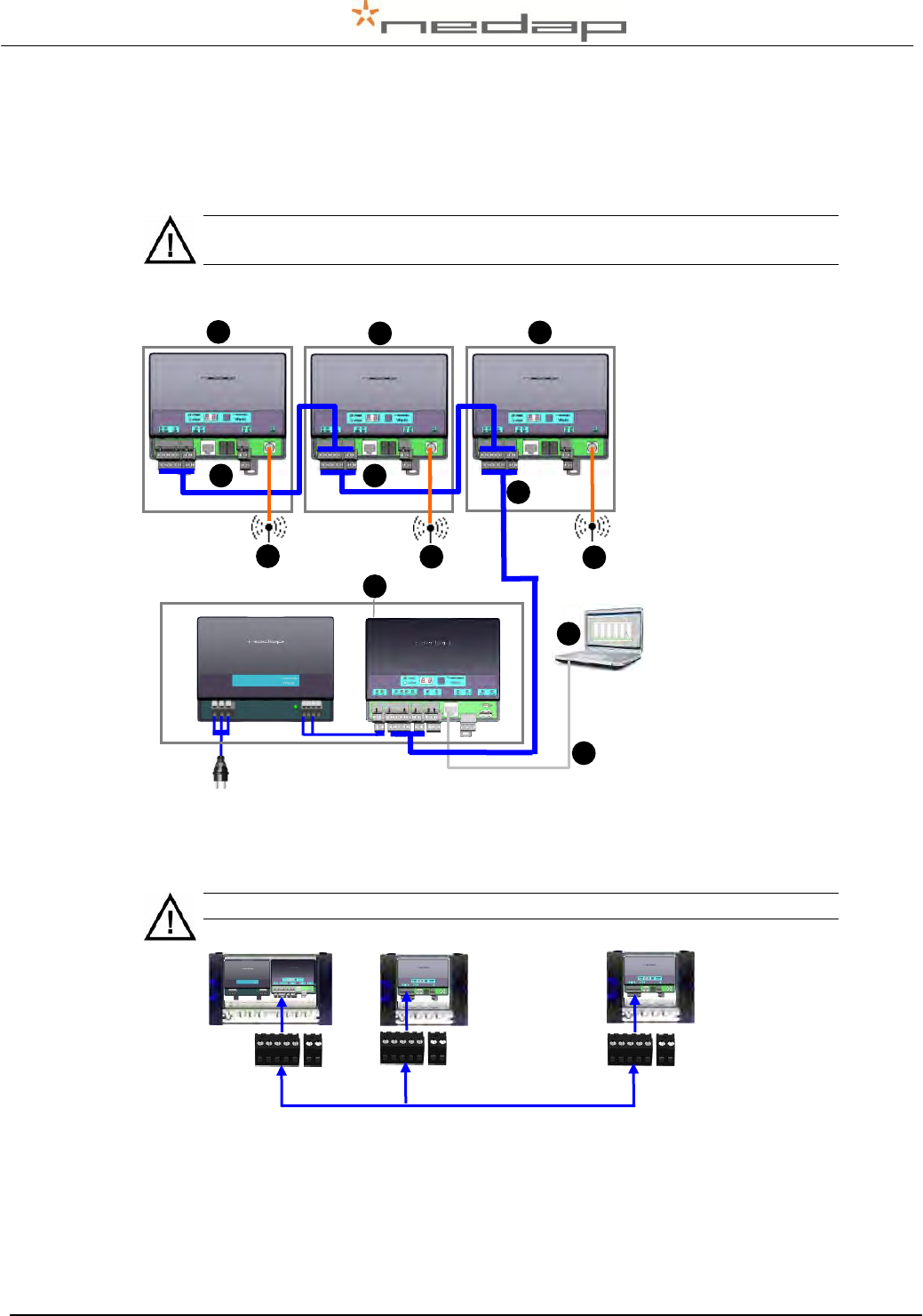
1. Mount the V-boxes 1 (with the antenna reader) and the V-box 2 (process unit with the power
supply and the VPU controller) on a wall. Pay attention to the maximum distance. See
Appendix E for more information about mounting the V-boxes.
The maximum cable length between the VPU and the last VP4101 is 200 meter
if only VP4101 readers are connected. Connect maximum 4 VP4101 readers.
2. Connect the VPU controller to the VP4101 antenna readers and to a PC.
1. VPU controller
(VP8001) in process
unit
2. VP4101 reader
3. Antenna
4. Network or PC
5. Communication cable
6. UTP cat5 cable
Figure 18. Overview process unit connected to one or more VP4101 readers
Prepare the length of the blue communication cable for the distance between the VPU and
the first VP4101 and prepare more cable for the distance between the VP4101 readers.
The maximum cable length between the VPU and the last VP4101 is 200 meter.
Figure 19. Connecting VPU and reader and the maximum cable length
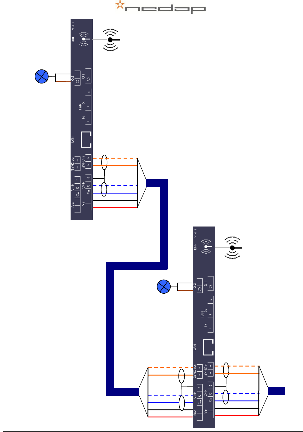
Put the communication cables through the cable glands, connect the communication cable
to the connectors and plug the connectors in the VPU controller and the VP4101. See
chapter 5 for more information and see the next page for a detailed wiring scheme for the
communication cable between the last two VP4101 readers.
Process
unit
← Max. 200 m. →
Last
VP4101
(max 4)
First
VP4101
VPU
6
L
e
n
gt
h
of
c
or
ri
d
or
(
m
)
1
1
L
e
n
gt
h
of
c
or
ri
d
or
(
m
)
4
L
e
n
gt
h
of
c
or
ri
d
or
(
m
)
5
L
e
n
gt
h
of
c
or
ri
d
or
(
m
)
2
L
e
n
gt
h
of
c
or
ri
d
or
(
m
)
3
1
L
e
n
gt
h
of
c
or
ri
d
or
(
m
)
VP4101
VP4101
VP4101
2
L
e
n
gt
h
of
c
or
ri
d
or
(
m
)
2
L
e
n
gt
h
of
c
or
ri
d
or
(
m
)
3
1
L
e
n
gt
h
of
c
or
ri
d
or
(
m
)
3
1
L
e
n
gt
h
of
c
or
ri
d
or
(
m
)
5
L
e
n
gt
h
of
c
or
ri
d
or
(
m
)
5
L
e
n
gt
h
of
c
or
ri
d
or
(
m
)
Nedap Velos – RealTime Heat detection service manual GB Manual version 1.6 / Page 36
white
Feed 2
brown
Feed 2
white
Feed 2
brown
Feed 2
Last VP4101
Second last VP4101
Heat detection VP4101 wiring in case of two or more antennas
blue white
Feed 2
red
Feed 2
black
Feed 2
orange
Feed 2
blue
Feed 2
orange white
Feed 2
Comm. cable
IN
red
Feed 2
black
Feed 2
orange
Feed 2
blue
Feed 2
orange white
Feed 2
red
Feed 2
black
Feed 2
orange
Feed 2
blue
Feed 2
orange white
Feed 2
Comm. cable
IN
Comm. cable
OUT

Nedap Velos – RealTime Heat detection service manual GB Manual version 1.6 / Page 37
3. Mount the antennas. See chapter 4.2 for more information about this.
4. Connect the antennas to the VP4101 readers. See chapter 5.2 for more information about
this.
5. Connect the process unit UTP cat5 cable to a network or PC.
6. Connect the power. Plug the Process unit power supply (VP2002) plug into an electricity
source.
7. Set the VP4101 address. The standard address is 01. In case of more than one antenna
use the instructions from appendix C to set the second address to e.g. 02, the third to 03
etc..
8. Set up the VPU network configuration. To set up the network
configuration make sure the VPU is operational and connected to the
network. Take the VPU Setup CD and run it on the connected PC to set
the IP address correctly automatically. See Appendix H for more
information about this.
9. Set up the VPU software. The VPU software is pre-installed. Start up the VPU program to
adjust some general program settings. See chapter 5.6 for more information about this.
Nedap Velos – RealTime Heat detection service manual GB Manual version 1.6 / Page 38
Appendix G Mobile access
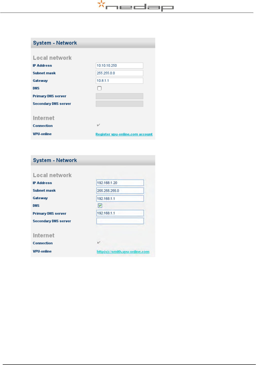
Default network settings of the VPU
(without an Internet connection) in
page Settings – System – Network.
Network settings of the VPU for
mobile access (with an Internet
connection and domain name
registration) in page Settings –
System – Network.
1. Change the IP address of the VPU so it is in the same range as the local network.*
2. Fill in the default gateway, normally this is the IP address of the router. Normally the default
gateway = primary DNS server.*
3. Enter any domain name. This is a free choice.*
4. Fill in the URL on the mobile phone to get mobile access to the Velos system.
* See the next page for more information about this.
3
2
2
1
Nedap Velos – RealTime Heat detection service manual GB Manual version 1.6 / Page 39
The Ref. numbers on this page refer to the numbers of the instructions on the previous page.
Ref. 1 and 2.
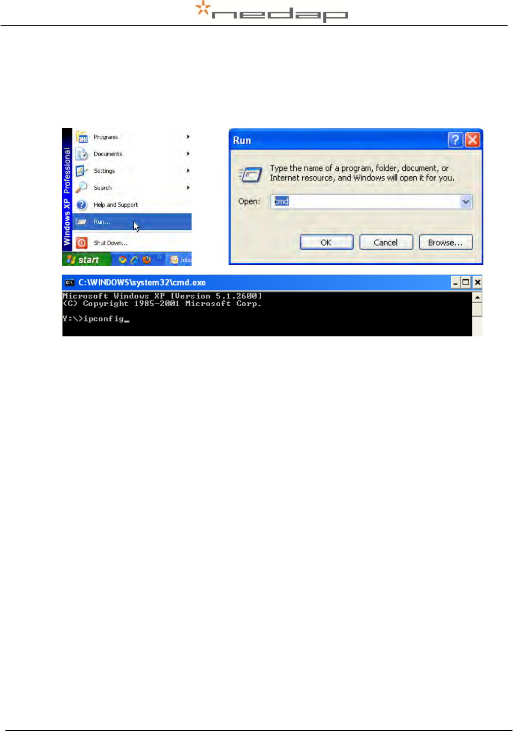
The IP address of the pc can be found by typing using the command “ipconfig” in the
commander, see the screenshots below:
Press enter to get the IP address, the subnet mask and the default gateway of the pc from the
commander. The same range means that the VPU can communicate with the router. When
using subnet mask 255.255.255.0 than the first three numbers of the IP address of the VPU
must be the same. The last number is a free choice, but the IP address must be a unique
number.
Ref. 3.
Enter any domain name. This is a free choice e.g. the name of the farm.
The mobile access will be operational if the domain name is registered and if the settings are
made correctly. If the network settings can not be set correctly, please pass on the
information from this attachment to an IT-specialist.
Nedap Velos – RealTime Heat detection service manual GB Manual version 1.6 / Page 40
Appendix H Setting up the VPU network configuration
To set up the network configuration make sure the VPU is operational and connected to the
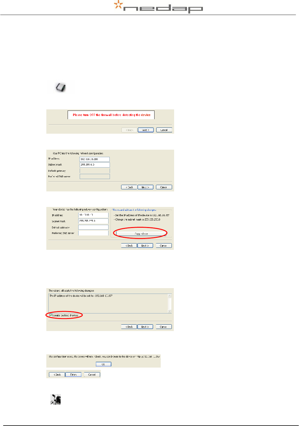
network. Take the IP Utility wizard CD and run it on the connected PC to set the IP address
correctly automatically.
1. Click on the IP utility wizard icon from the IP wizard CD.
2. Turn off the fire wall (in the Control panel - Security centre) and click Next.
3. Click Next.
4. Click on copy advice if this is suggested and click Next.
If the VPU is not found check if the VPU is running and if the network is connected correctly.
Click Back and try again. Contact a network specialist if necessary.
5. Click Next. The IP address will now be changed and a VPU desktop shortcut will be
created on the desktop.
Click OK.
6. Click on OK and on Finish.
7. The VPU desktop shortcut is now on the desktop. Click on it to start the program.

Nedap Velos – RealTime Heat detection service manual GB Manual version 1.6 / Page 41
If necessary see the VP8001 VPU manual on the Nedap Velos Software VP8001 CD (art. nr.
9937269) that is supplied with the Heat detection system for more information about adjustment
of the VPU settings in the LAN network.
VP8001 Software Setup Tool and Documentation CD cover
VP8001 VPU manual on CD
Nedap Velos – RealTime Heat detection service manual GB Manual version 1.6 / Page 42
Appendix I Using synchronisation with a Nedap server
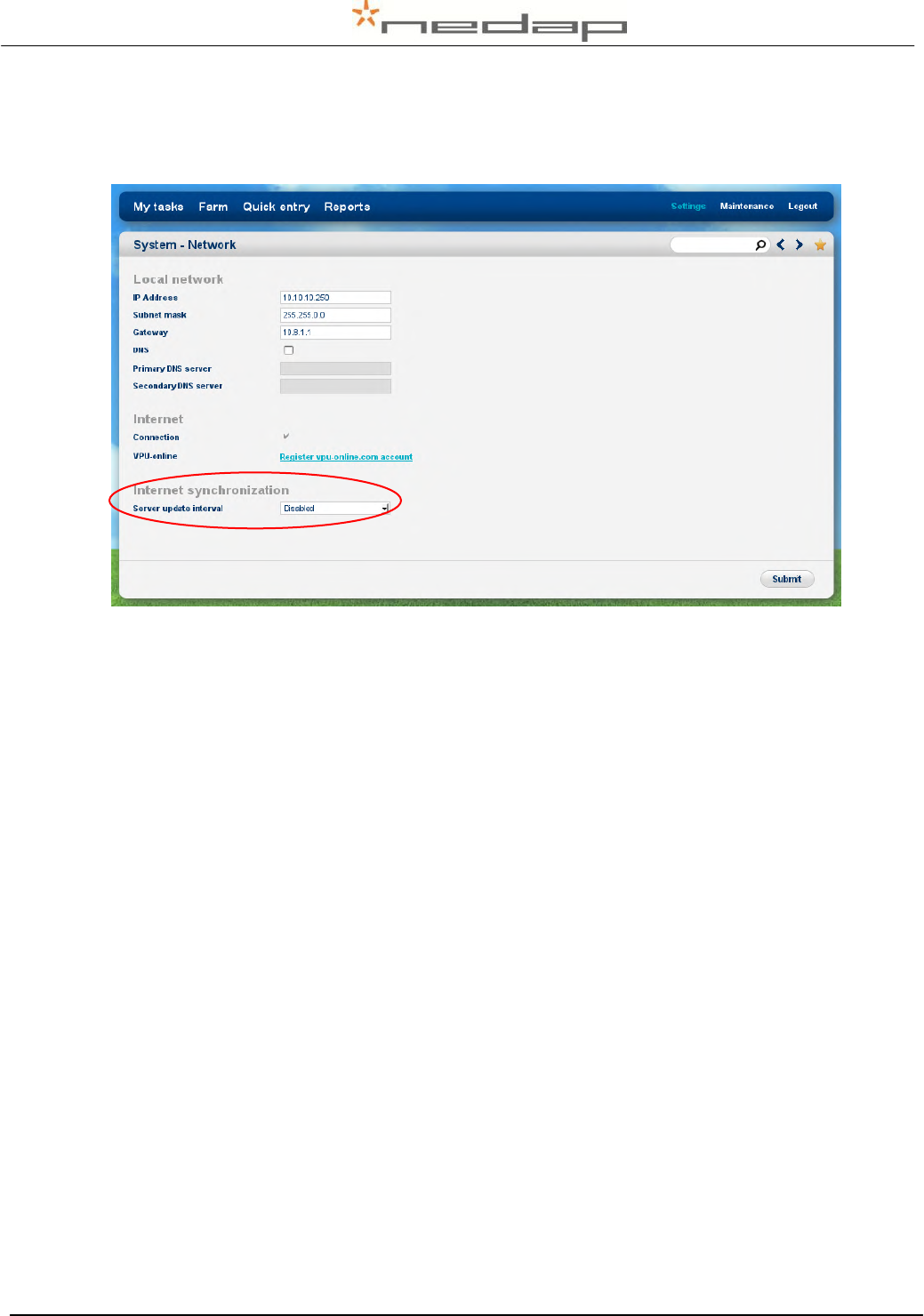
Optionally adjust the Server settings in the page Settings > System - Network e.g. when using
synchronisation with a Nedap server. Press Submit to save the changes.
Nedap Velos – RealTime Heat detection service manual GB Manual version 1.6 / Page 43
Appendix J Declaration
