Nedap N V SENSDATA Sensor for the Wireless Space Count system for parking lots User Manual
N. V. Nederlandsche Apparatenfabriek NEDAP Sensor for the Wireless Space Count system for parking lots
UserManual.wiki
>
Nedap N V
>
SENSDATA User Manual
User manual
Navigation menu
Upload a User Manual
Namespaces
Wiki Guide
HTML
PDF
Info
Views
User Manual
Discussion / Help
Navigation
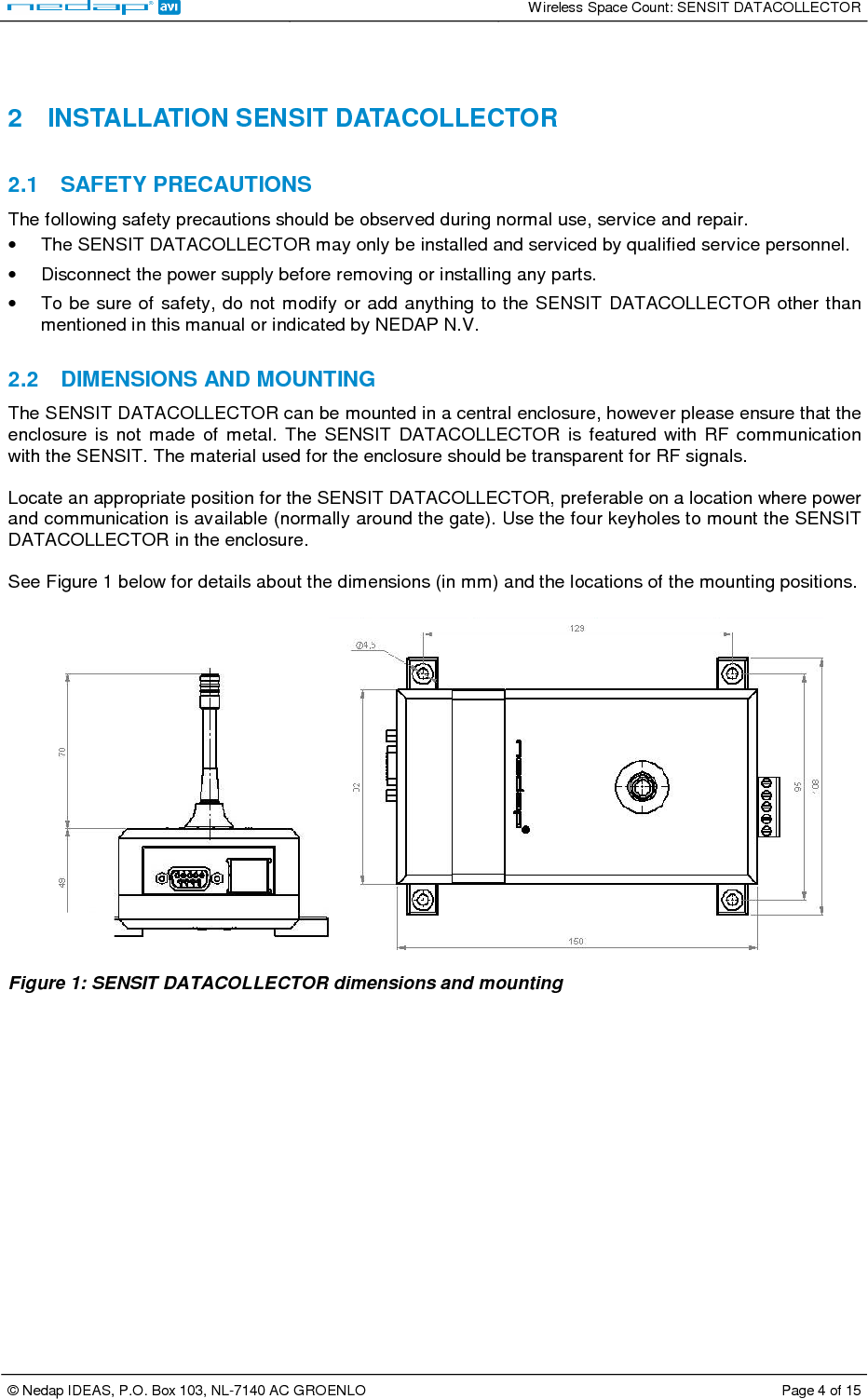
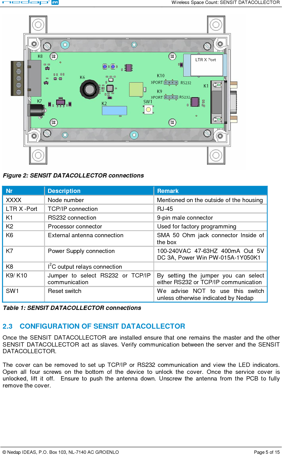
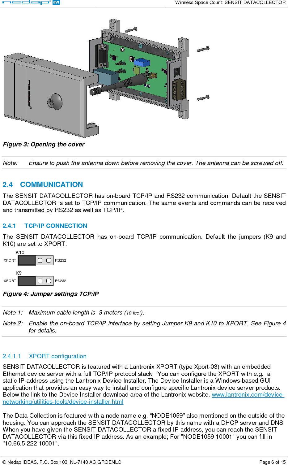
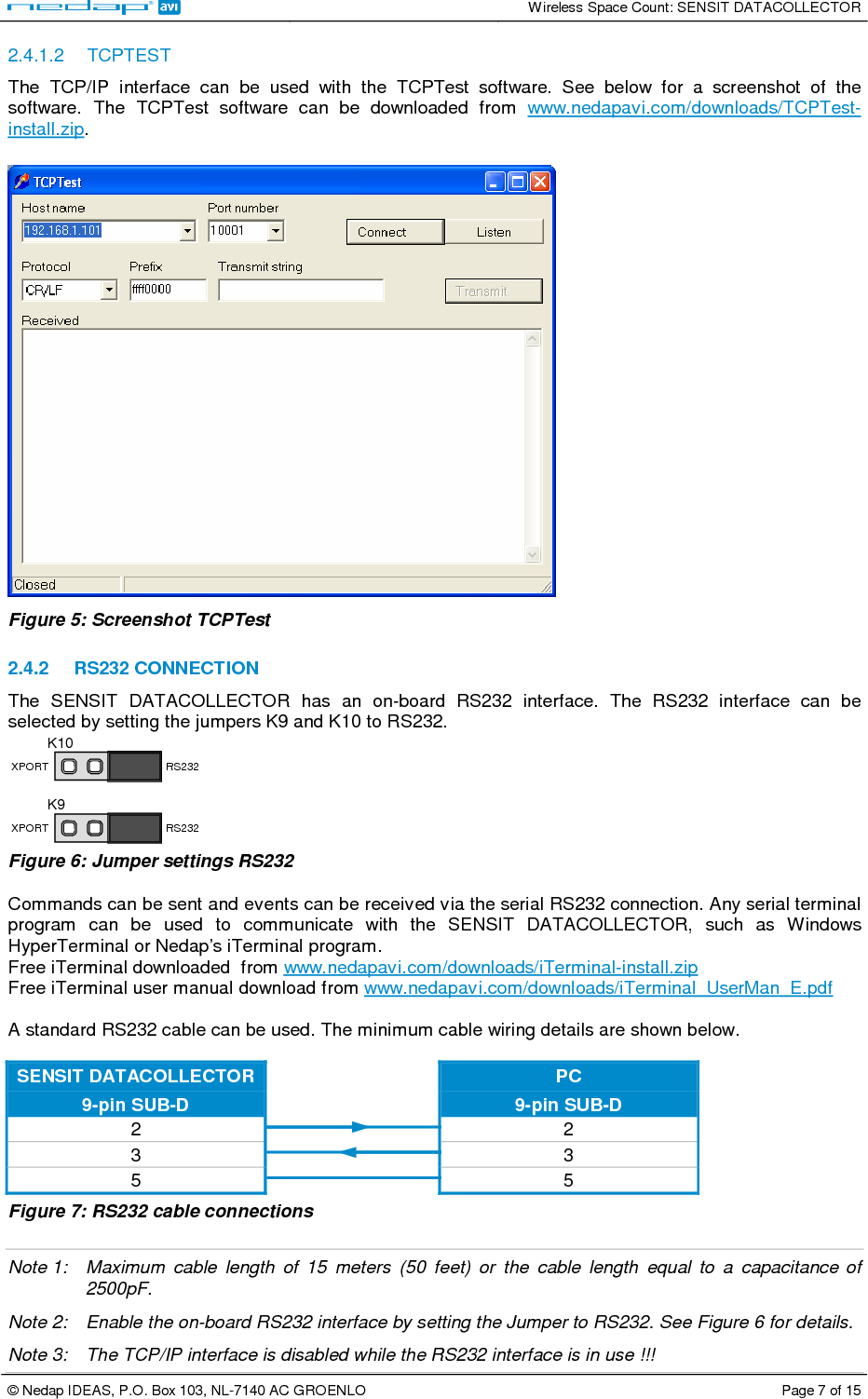
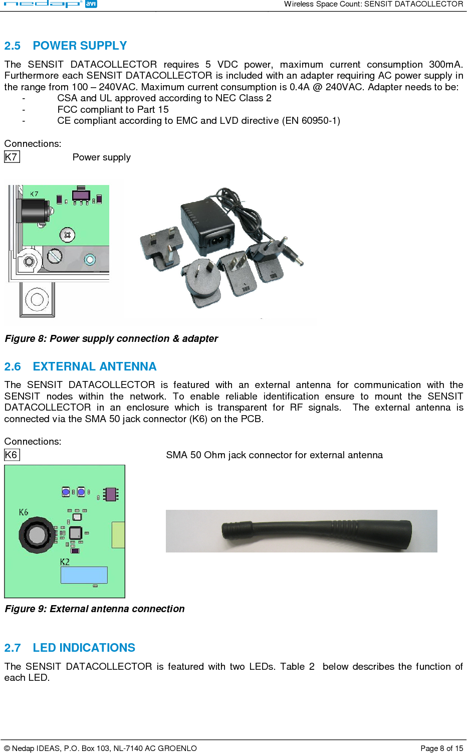
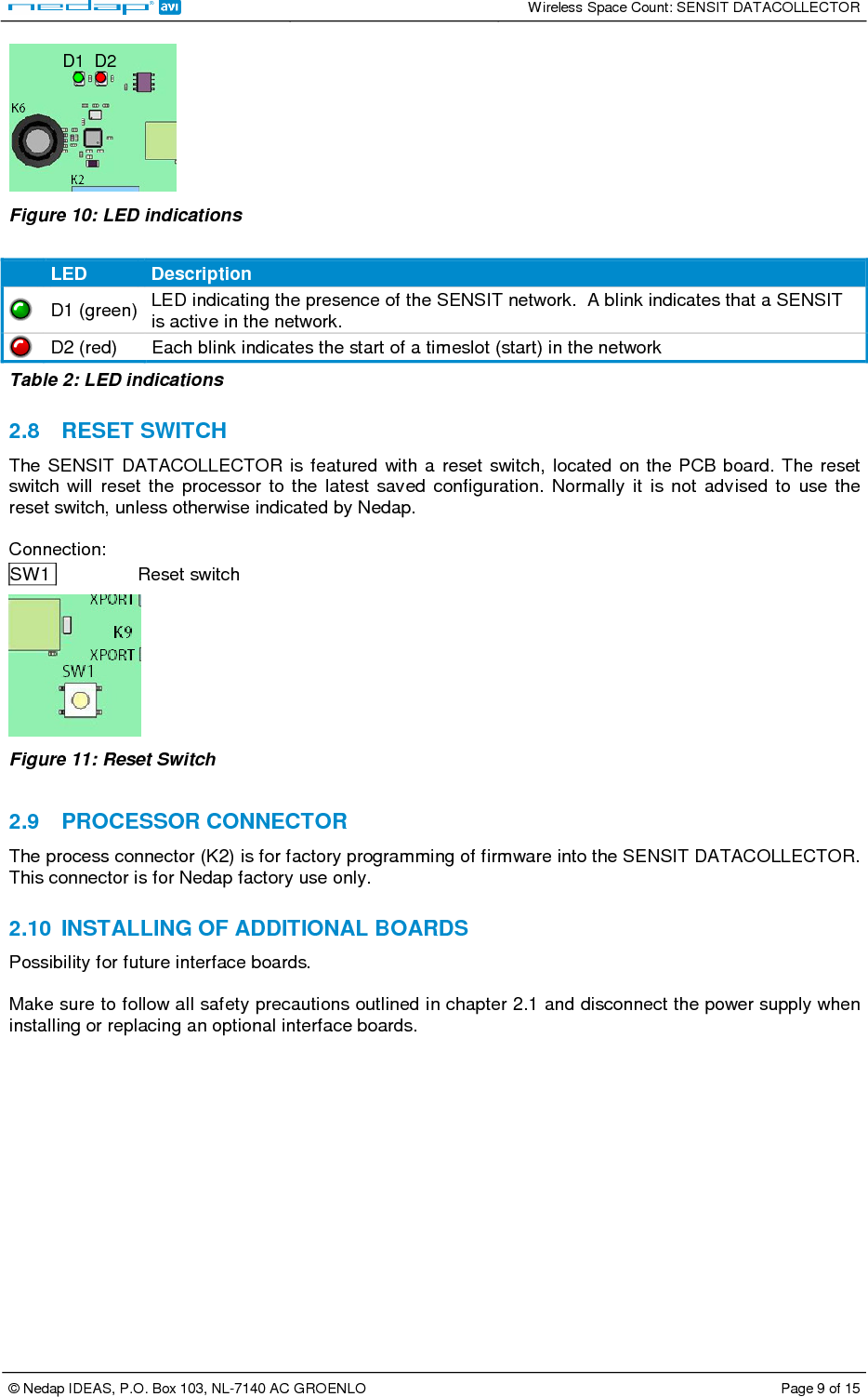
![Wireless Space Count: SENSIT DATACOLLECTOR © Nedap IDEAS, P.O. Box 103, NL-7140 AC GROENLO Page 10 of 15 3 DATA CONFIGURATION The Data format of messages from the SENSIT and the SENSIT DATACOLLECTOR are the same whether TCP/IP or RS232 communication is applied. The SENSIT is default already configured and for most installations this should be all right. The below mentioned command messages are therefore only required if you want to change specific settings. 3.1 DATA FORMAT The data format is fixed: Baud rate: 115200 Data bits: 8 Parity: None Stop bits: 1 3.2 COMMAND MESSAGE FORMAT TO THE NODE(S) Commands messages that are sent to the SENSIT should be sent in the following format: XXXX0000IIII[DDDD][DDDD].... XXXX Node ID (FFFF is broadcast) 0000 Message number; always four zeros IIII Instruction code DDDD Optional data word 16 bit The SENSIT DATACOLLECTOR software replaces the 0000 message number with an automatic increment message number between 0080 and 00FF. When your own interface software is making the message number it is highly recommended to use the same range. 3.3 DATA MESSAGE FORMAT FROM THE NODE(S) The data message format from the SENSIT is similar to the command message format, except YYYY are not four zeros but an internal message number. The node adds an internal message number to a created event message, in the range from 0000 to 007F. XXXXYYYYIIII[DDDD][DDDD].... XXXX Node ID, FFFF is broadcast YYYY Internal message number IIII Instruction DDDD optional data word 16 bit The four MSB bits of the Instruction word are the (not) acknowledge and type of data flags? CXXX The data field contains an ASCII string (example command 00CA) 4XXX Data from a node (always) 5XXX Error in instruction 6XXX Unknown instruction More detailed information about all the commands can be found in the Wireless Space Count Install Guide.](https://usermanual.wiki/Nedap-N-V/SENSDATA/User-Guide-1234541-Page-10.png)