Nedap N V SENSDATA Sensor for the Wireless Space Count system for parking lots User Manual
N. V. Nederlandsche Apparatenfabriek NEDAP Sensor for the Wireless Space Count system for parking lots
User manual
2009-11-24
This information is furnished for guidance, and with no guarantee as to its accuracy or completeness; its publication
conveys no license under any patent or other right, nor does the publisher assume liability for any consequence of
its use; specifications and availability of goods mentioned in it are subject to change without notice; it is not to be
reproduced in any way, in whole or in part, without the written consent of the publisher.
© Nedap IDEAS, P.O. Box 103, NL-7140 AC GROENLO Page 1 of 15
Wireless Space
Count
Manual SENSIT DATACOLLECTOR

Wireless Space Count: SENSIT DATACOLLECTOR
© Nedap IDEAS, P.O. Box 103, NL-7140 AC GROENLO Page 2 of 15
CONTENTS
1
INTRODUCTION..............................................................................................................................3
1.1
PRODUCT DESCRIPTION SENSIT DATACOLLECTOR .......................................... 3
2
INSTALLATION SENSIT DATACOLLECTOR ..................................................................................4
2.1
SAFETY PRECAUTIONS........................................................................................... 4
2.2
DIMENSIONS AND MOUNTING ................................................................................ 4
2.3
CONFIGURATION OF SENSIT DATACOLLECTOR.................................................. 5
2.4
COMMUNICATION..................................................................................................... 6
2.4.1
TCP/IP CONNECTION...............................................................................................6
2.4.2
RS232 CONNECTION ...............................................................................................7
2.5
POWER SUPPLY ...................................................................................................... 8
2.6
EXTERNAL ANTENNA .............................................................................................. 8
2.7
LED INDICATIONS .................................................................................................... 8
2.8
RESET SWITCH ........................................................................................................ 9
2.9
PROCESSOR CONNECTOR .................................................................................... 9
2.10
INSTALLING OF ADDITIONAL BOARDS .................................................................. 9
3
DATA CONFIGURATION...............................................................................................................10
3.1
DATA FORMAT........................................................................................................ 10
3.2
COMMAND MESSAGE FORMAT TO THE NODE(S) .............................................. 10
3.3
DATA MESSAGE FORMAT FROM THE NODE(S).................................................. 10
4
PROJECT SUPPORT ....................................................................................................................11
4.1
SITE SURVEY & INSTALLATION ADVICE.............................................................. 11
4.2
ON-SITE CERTIFICATION....................................................................................... 11
5
FCC AND IC DECLARATION.........................................................................................................12
5.1
Compliance statements (part15.19) ......................................................................... 12
5.2
Warning (part15.21) ................................................................................................. 12
5.3
RF Exposure (OET Bulletin 65)................................................................................ 12
5.4
Information to the User (Part 15.106(b)) .................................................................. 12
6
TECHNICAL SPECIFICATIONS.....................................................................................................13
A
PART NUMBERS...........................................................................................................................15

Wireless Space Count: SENSIT DATACOLLECTOR
© Nedap IDEAS, P.O. Box 103, NL-7140 AC GROENLO Page 3 of 15
1 INTRODUCTION
The Wireless Space Count system facilitates accurate measurement on occupancy of individual parking
spaces in car parks, and on-street parking spaces. This information can be used to guide traffic to free
parking spaces but can also be used for on-street parking enforcement and overstay detection. For on-
street enforcement the number of occupied parking spaces can be compared with the number of
payments realized by the pay station. For overstay detection the system alerts instantly a parking officer
to the presence of nearby overstaying vehicles. Based on this information you can exactly determine
which space to enforce.
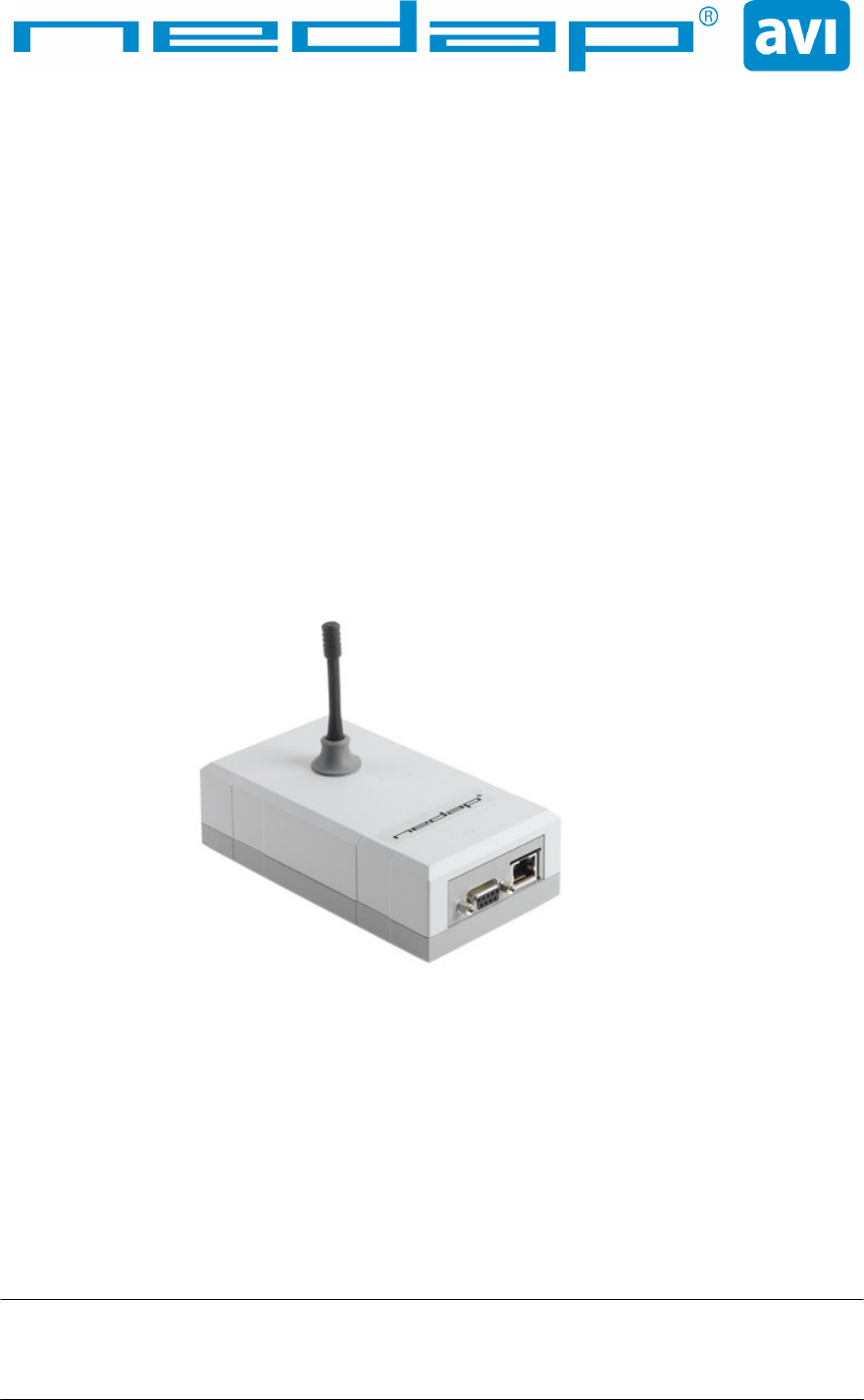
1.1 PRODUCT DESCRIPTION SENSIT DATACOLLECTOR
The actual status (occupancy) of the SENSIT is collected by one or more SENSIT DATACOLLECTOR.
The SENSIT DATACOLLECTOR is the interface between the SENSIT and the host system The SENSIT
DATACOLLECTOR transmits status information about the sensors to the host system through RS232 or
Ethernet communication. Over RS232 the SENSIT DATACOLLECTOR communicates via a serial
connection to the host. Over TCP/IP the SENSIT DATACOLLECTOR communicates directly on your
LAN network. The TCP/IP communication allows you to decide on direct communication or to make use
of a database application.
For a parking site you need at least one SENSIT DATACOLLECTOR and a SENSIT per parking bay.
One SENSIT DATACOLLECTOR is required per 100 parking bays. All SENSIT DATACOLLECTOR
must be separated as far as possible from each other, preferably with a 200+ network at every corner of
the site a SENSIT DATACOLLECTOR.
Note: This manual is not intended for the end user, the SENSIT DATACOLLECTOR shall be installed
by a professional. The case is preventing to remove the antenna so that the end user cannot
and shall not detach it from the device.
Wireless Space Count: SENSIT DATACOLLECTOR
© Nedap IDEAS, P.O. Box 103, NL-7140 AC GROENLO Page 4 of 15
2 INSTALLATION SENSIT DATACOLLECTOR
2.1 SAFETY PRECAUTIONS
The following safety precautions should be observed during normal use, service and repair.
• The SENSIT DATACOLLECTOR may only be installed and serviced by qualified service personnel.
• Disconnect the power supply before removing or installing any parts.
• To be sure of safety, do not modify or add anything to the SENSIT DATACOLLECTOR other than
mentioned in this manual or indicated by NEDAP N.V.
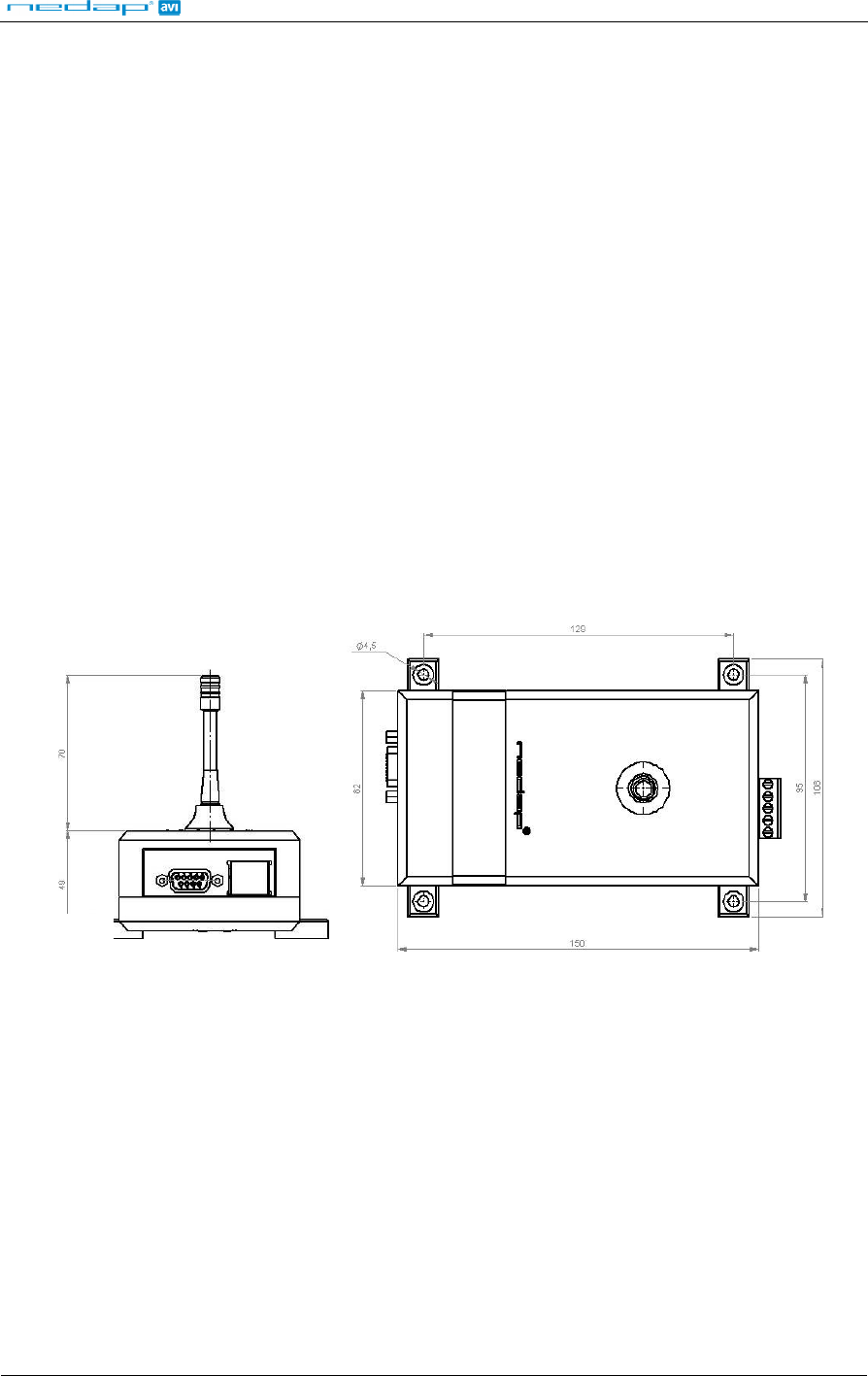
2.2 DIMENSIONS AND MOUNTING
The SENSIT DATACOLLECTOR can be mounted in a central enclosure, however please ensure that the
enclosure is not made of metal. The SENSIT DATACOLLECTOR is featured with RF communication
with the SENSIT. The material used for the enclosure should be transparent for RF signals.
Locate an appropriate position for the SENSIT DATACOLLECTOR, preferable on a location where power
and communication is available (normally around the gate). Use the four keyholes to mount the SENSIT
DATACOLLECTOR in the enclosure.
See Figure 1 below for details about the dimensions (in mm) and the locations of the mounting positions.
Figure 1: SENSIT DATACOLLECTOR dimensions and mounting
Wireless Space Count: SENSIT DATACOLLECTOR
© Nedap IDEAS, P.O. Box 103, NL-7140 AC GROENLO Page 5 of 15
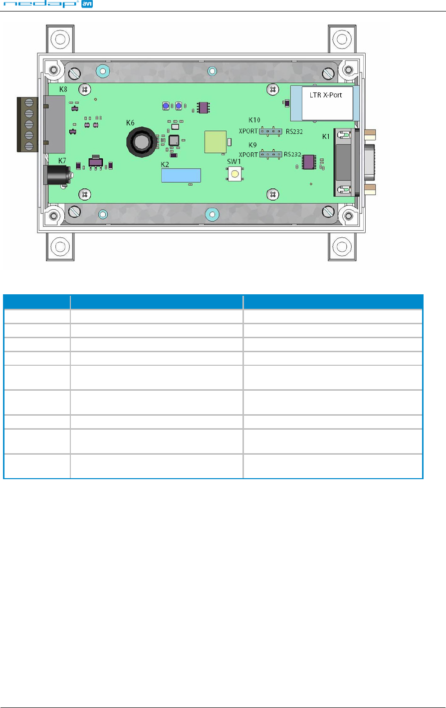
Figure 2: SENSIT DATACOLLECTOR connections
Nr Description Remark
XXXX Node number Mentioned on the outside of the housing
LTR X -Port TCP/IP connection RJ-45
K1 RS232 connection 9-pin male connector
K2 Processor connector Used for factory programming
K6 External antenna connection SMA 50 Ohm jack connector Inside of
the box
K7 Power Supply connection 100-240VAC 47-63HZ 400mA Out 5V
DC 3A, Power Win PW-015A-1Y050K1
K8 I
2
C output relays connection
K9/ K10 Jumper to select RS232 or TCP/IP
communication
By setting the jumper you can select
either RS232 or TCP/IP communication
SW1 Reset switch We advise NOT to use this switch
unless otherwise indicated by Nedap
Table 1: SENSIT DATACOLLECTOR connections
2.3 CONFIGURATION OF SENSIT DATACOLLECTOR
Once the SENSIT DATACOLLECTOR are installed ensure that one remains the master and the other
SENSIT DATACOLLECTOR act as slaves. Verify communication between the server and the SENSIT
DATACOLLECTOR.
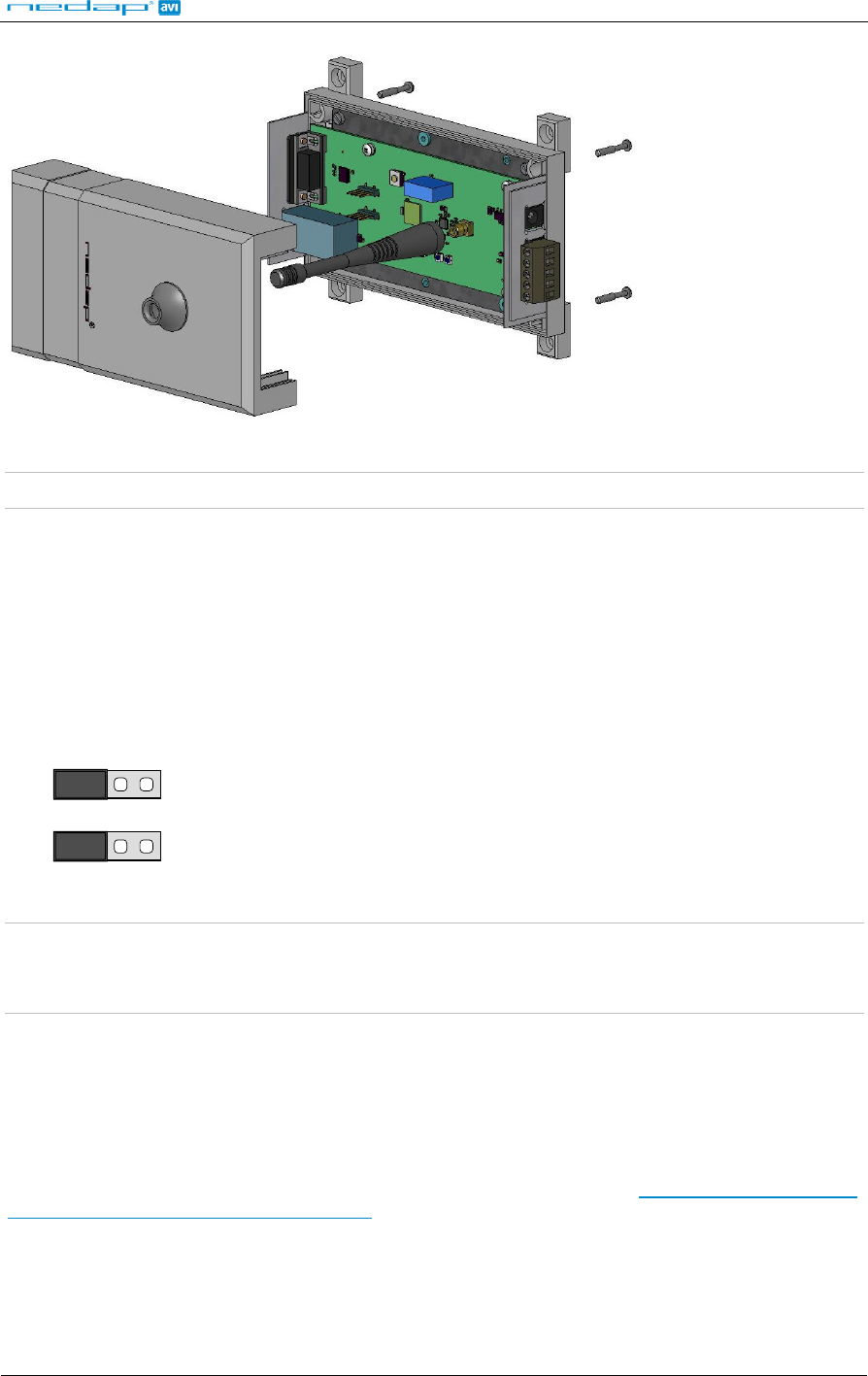
The cover can be removed to set up TCP/IP or RS232 communication and view the LED indicators.
Open all four screws on the bottom of the device to unlock the cover. Once the service cover is
unlocked, lift it off. Ensure to push the antenna down. Unscrew the antenna from the PCB to fully
remove the cover.
Wireless Space Count: SENSIT DATACOLLECTOR
© Nedap IDEAS, P.O. Box 103, NL-7140 AC GROENLO Page 6 of 15
Figure 3: Opening the cover
Note: Ensure to push the antenna down before removing the cover. The antenna can be screwed off.
2.4 COMMUNICATION
The SENSIT DATACOLLECTOR has on-board TCP/IP and RS232 communication. Default the SENSIT
DATACOLLECTOR is set to TCP/IP communication. The same events and commands can be received
and transmitted by RS232 as well as TCP/IP.
2.4.1 TCP/IP CONNECTION
The SENSIT DATACOLLECTOR has on-board TCP/IP communication. Default the jumpers (K9 and
K10) are set to XPORT.
K10
K9
XPORT
XPORT
RS232
RS232
Figure 4: Jumper settings TCP/IP
Note 1: Maximum cable length is 3 meters (10 feet).
Note 2: Enable the on-board TCP/IP interface by setting Jumper K9 and K10 to XPORT. See Figure 4
for details.
2.4.1.1 XPORT configuration
SENSIT DATACOLLECTOR is featured with a Lantronix XPORT (type Xport-03) with an embedded
Ethernet device server with a full TCP/IP protocol stack. You can configure the XPORT with e.g. a
static IP-address using the Lantronix Device Installer. The Device Installer is a Windows-based GUI
application that provides an easy way to install and configure specific Lantronix device server products.
Below the link to the Device Installer download area of the Lantronix website. www.lantronix.com/device-
networking/utilities-tools/device-installer.html
The Data Collection is featured with a node name e.g. “NODE1059” also mentioned on the outside of the
housing. You can approach the SENSIT DATACOLLECTOR by this name with a DHCP server and DNS.
When you have given the SENSIT DATACOLLECTOR a fixed IP address, you can reach the SENSIT
DATACOLLECTOR via this fixed IP address. As an example; For "NODE1059 10001" you can fill in
"10.66.5.222 10001".
Wireless Space Count: SENSIT DATACOLLECTOR
© Nedap IDEAS, P.O. Box 103, NL-7140 AC GROENLO Page 7 of 15
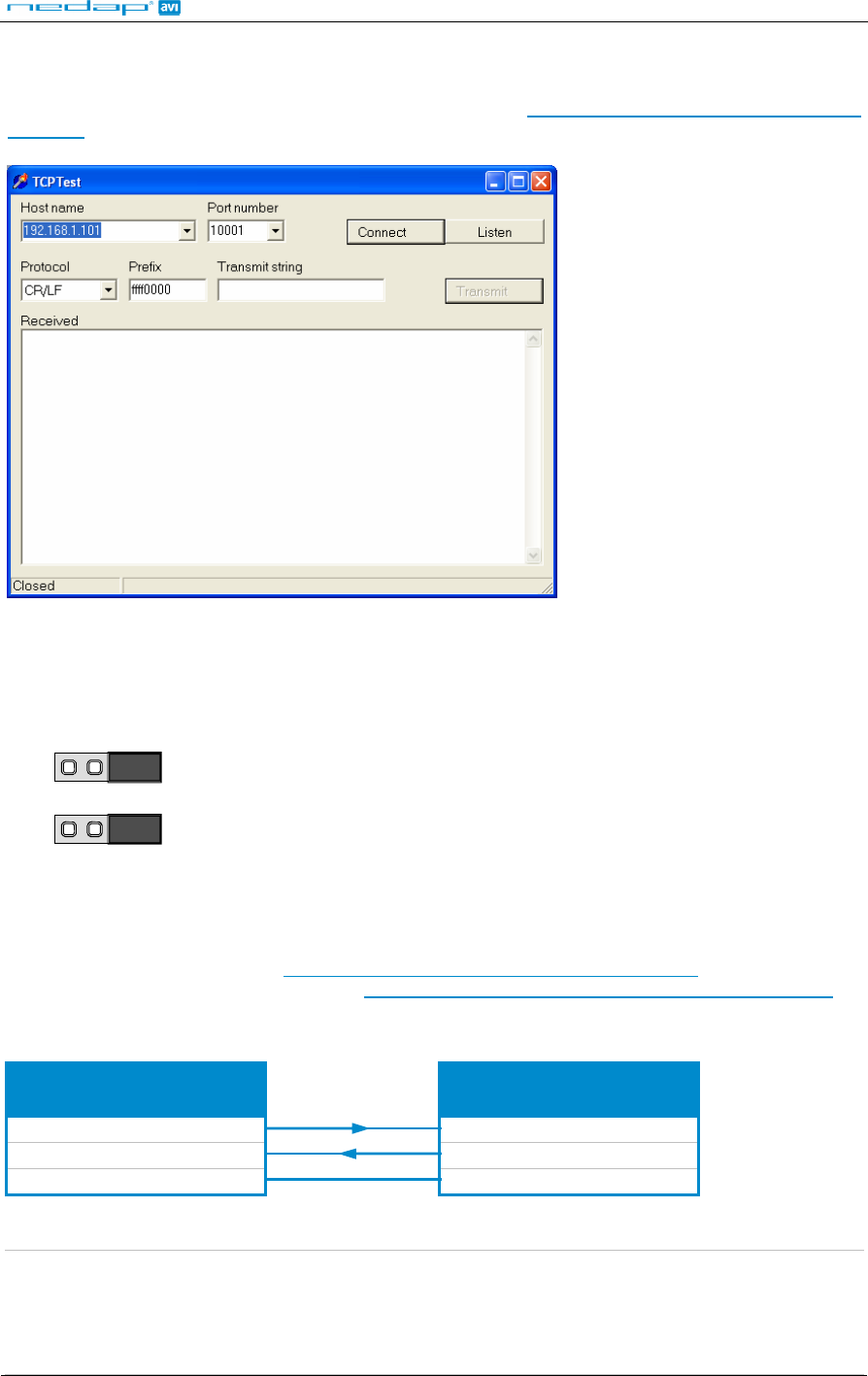
2.4.1.2 TCPTEST
The TCP/IP interface can be used with the TCPTest software. See below for a screenshot of the
software. The TCPTest software can be downloaded from www.nedapavi.com/downloads/TCPTest-
install.zip.
Figure 5: Screenshot TCPTest
2.4.2 RS232 CONNECTION
The SENSIT DATACOLLECTOR has an on-board RS232 interface. The RS232 interface can be
selected by setting the jumpers K9 and K10 to RS232.
K10
K9
XPORT
XPORT
RS232
RS232
Figure 6: Jumper settings RS232
Commands can be sent and events can be received via the serial RS232 connection. Any serial terminal
program can be used to communicate with the SENSIT DATACOLLECTOR, such as Windows
HyperTerminal or Nedap’s iTerminal program.
Free iTerminal downloaded from www.nedapavi.com/downloads/iTerminal-install.zip
Free iTerminal user manual download from www.nedapavi.com/downloads/iTerminal_UserMan_E.pdf
A standard RS232 cable can be used. The minimum cable wiring details are shown below.
SENSIT DATACOLLECTOR
PC
9-pin SUB-D 9-pin SUB-D
2 2
3 3
5 5
Figure 7: RS232 cable connections
Note 1: Maximum cable length of 15 meters (50 feet) or the cable length equal to a capacitance of
2500pF.
Note 2: Enable the on-board RS232 interface by setting the Jumper to RS232. See Figure 6 for details.
Note 3: The TCP/IP interface is disabled while the RS232 interface is in use !!!
Wireless Space Count: SENSIT DATACOLLECTOR
© Nedap IDEAS, P.O. Box 103, NL-7140 AC GROENLO Page 8 of 15
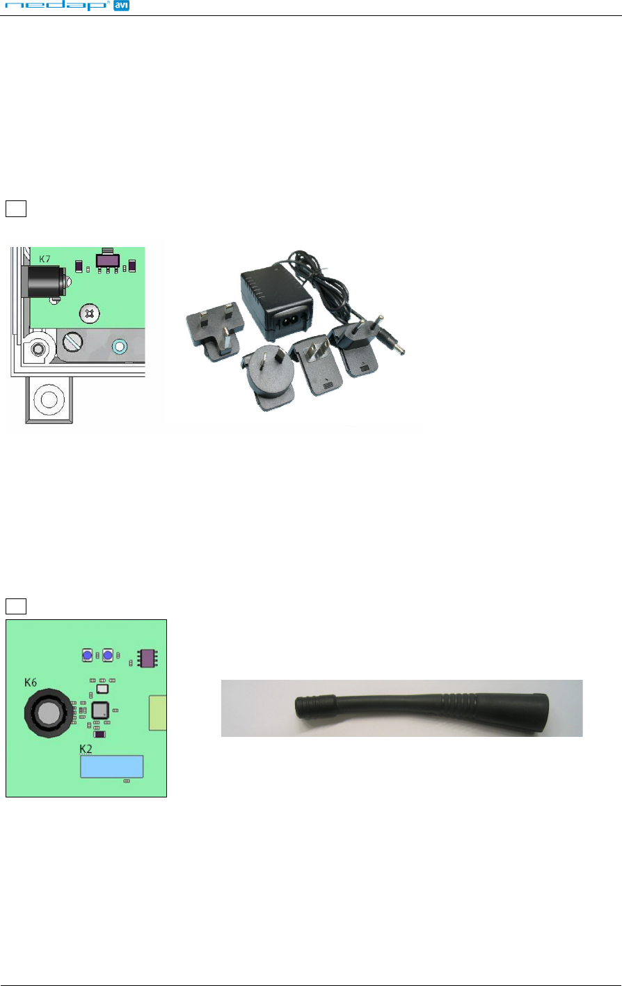
2.5 POWER SUPPLY
The SENSIT DATACOLLECTOR requires 5 VDC power, maximum current consumption 300mA.
Furthermore each SENSIT DATACOLLECTOR is included with an adapter requiring AC power supply in
the range from 100 – 240VAC. Maximum current consumption is 0.4A @ 240VAC. Adapter needs to be:
- CSA and UL approved according to NEC Class 2
- FCC compliant to Part 15
- CE compliant according to EMC and LVD directive (EN 60950-1)
Connections:
K7 Power supply
Figure 8: Power supply connection & adapter
2.6 EXTERNAL ANTENNA
The SENSIT DATACOLLECTOR is featured with an external antenna for communication with the
SENSIT nodes within the network. To enable reliable identification ensure to mount the SENSIT
DATACOLLECTOR in an enclosure which is transparent for RF signals. The external antenna is
connected via the SMA 50 jack connector (K6) on the PCB.
Connections:
K6 SMA 50 Ohm jack connector for external antenna
Figure 9: External antenna connection
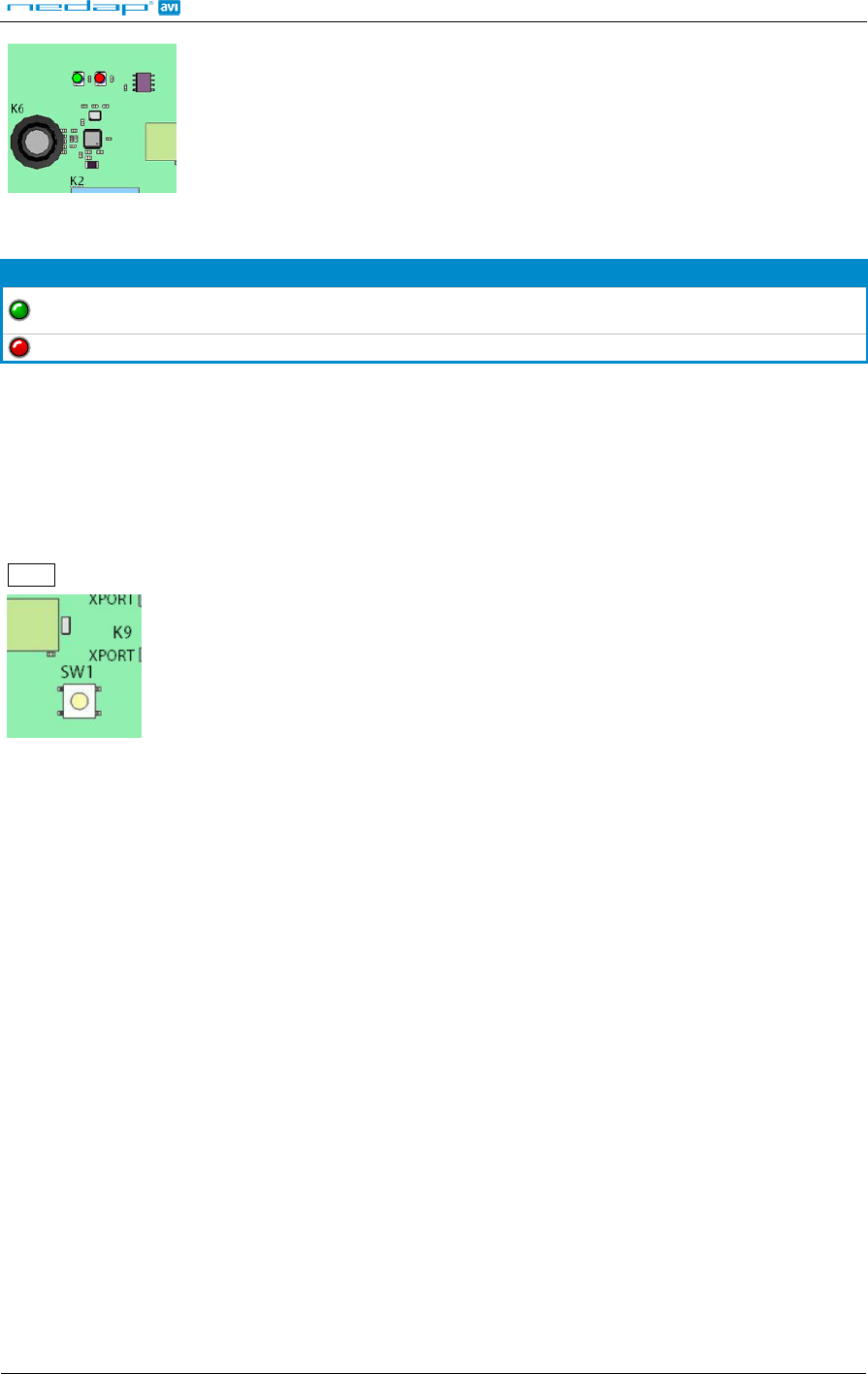
2.7 LED INDICATIONS
The SENSIT DATACOLLECTOR is featured with two LEDs. Table 2 below describes the function of
each LED.
Wireless Space Count: SENSIT DATACOLLECTOR
© Nedap IDEAS, P.O. Box 103, NL-7140 AC GROENLO Page 9 of 15
D1 D2
Figure 10: LED indications
LED Description
D1 (green)
LED indicating the presence of the SENSIT network. A blink indicates that a SENSIT
is active in the network.
D2 (red) Each blink indicates the start of a timeslot (start) in the network
Table 2: LED indications
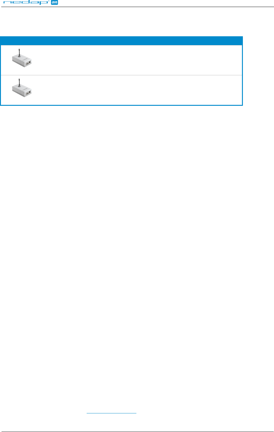
2.8 RESET SWITCH
The SENSIT DATACOLLECTOR is featured with a reset switch, located on the PCB board. The reset
switch will reset the processor to the latest saved configuration. Normally it is not advised to use the
reset switch, unless otherwise indicated by Nedap.
Connection:
SW1 Reset switch
Figure 11: Reset Switch
2.9 PROCESSOR CONNECTOR
The process connector (K2) is for factory programming of firmware into the SENSIT DATACOLLECTOR.
This connector is for Nedap factory use only.
2.10 INSTALLING OF ADDITIONAL BOARDS
Possibility for future interface boards.
Make sure to follow all safety precautions outlined in chapter 2.1 and disconnect the power supply when
installing or replacing an optional interface boards.

Wireless Space Count: SENSIT DATACOLLECTOR
© Nedap IDEAS, P.O. Box 103, NL-7140 AC GROENLO Page 10 of 15
3 DATA CONFIGURATION
The Data format of messages from the SENSIT and the SENSIT DATACOLLECTOR are the same
whether TCP/IP or RS232 communication is applied. The SENSIT is default already configured and for
most installations this should be all right. The below mentioned command messages are therefore only
required if you want to change specific settings.
3.1 DATA FORMAT
The data format is fixed:
Baud rate: 115200
Data bits: 8
Parity: None
Stop bits: 1
3.2 COMMAND MESSAGE FORMAT TO THE NODE(S)
Commands messages that are sent to the SENSIT should be sent in the following format:
XXXX0000IIII[DDDD][DDDD]....
XXXX Node ID (FFFF is broadcast)
0000 Message number; always four zeros
IIII Instruction code
DDDD Optional data word 16 bit
The SENSIT DATACOLLECTOR software replaces the 0000 message number with an automatic
increment message number between 0080 and 00FF. When your own interface software is making the
message number it is highly recommended to use the same range.
3.3 DATA MESSAGE FORMAT FROM THE NODE(S)
The data message format from the SENSIT is similar to the command message format, except YYYY
are not four zeros but an internal message number. The node adds an internal message number to a
created event message, in the range from 0000 to 007F.
XXXXYYYYIIII[DDDD][DDDD]....
XXXX Node ID, FFFF is broadcast
YYYY Internal message number
IIII Instruction
DDDD optional data word 16 bit
The four MSB bits of the Instruction word are the (not) acknowledge and type of data flags?
CXXX The data field contains an ASCII string (example command 00CA)
4XXX Data from a node (always)
5XXX Error in instruction
6XXX Unknown instruction
More detailed information about all the commands can be found in the Wireless Space Count Install
Guide.

Wireless Space Count: SENSIT DATACOLLECTOR
© Nedap IDEAS, P.O. Box 103, NL-7140 AC GROENLO Page 11 of 15
4 PROJECT SUPPORT
Based on our thorough project analysis including configuration and installation advice we can offer the
customer the best AVI solution.
4.1 SITE SURVEY & INSTALLATION ADVICE
This will consist of an engineer visiting the site to visually inspect and analyze the location. We will then
carry out calculations and provide you with detailed configuration and installation advice for the Wireless
Space Count equipment for a specific project.
4.2 ON-SITE CERTIFICATION
An engineer will visit the site to inspect the installation of the equipment on reliable and accurate
detection. Nedap engineers are not involved in installation (wiring) of any equipment. The installation
must be completed before the engineer arrives on-site. We will ensure that the operation confirms our
commissioning requirements, only on condition of prior given installation advice.

Wireless Space Count: SENSIT DATACOLLECTOR
© Nedap IDEAS, P.O. Box 103, NL-7140 AC GROENLO Page 12 of 15
5 FCC AND IC DECLARATION
5.1 Compliance statements (part15.19)
This device complies with part 15 of the FCC Rules and to RSS210 of Industry Canada.
Operating is subject to the following two conditions:
(1) This device may not cause harmful interference, and
(2) This device must accept any interference received, including interference that may cause undesired
operation.
5.2 Warning (part15.21)
Changes or modifications not expressly approved by party responsible for compliance could void the
user’s authority to operate the equipment.
This in particular is applicable for the antenna which is delivered with the SENSIT DATACOLLECTOR.
5.3 RF Exposure (OET Bulletin 65)
To comply with FCC RF exposure requirements for mobile transmitting devices, this transmitter should
only be used or installed at locations where there is at least 20cm separation distance between the
antenna and all persons.
5.4 Information to the User (Part 15.106(b))
Note: This equipment has been tested and found to comply with the limits for a class B digital device,
pursuant to part 15 of the FCC Rules. These limits are designed to provide reasonable protection against
harmful interference in a residential installation. This equipment generates uses and can radiate radio
frequent energy and, if not installed and used in accordance with the instructions, may cause harmful
interference to radio communications.
However, there is no guarantee that interference will not occur in a particular installation. If this
equipment does not cause harmful interference to radio or television reception, which can be determine
by turning the equipment off and on, the user is encouraged to try to correct the interference by one or
more of the following measures:
- Reorient or relocate some node
- Connect the equipment into an outlet on a circuit different from that to which the SENSIT
DATACOLLECTOR is connected.
- Consult the dealer or an experienced radio/TV technician for help.

Wireless Space Count: SENSIT DATACOLLECTOR
© Nedap IDEAS, P.O. Box 103, NL-7140 AC GROENLO Page 13 of 15
6 TECHNICAL SPECIFICATIONS
SENSIT DATACOLLECTOR (EU) 9889582
Operating frequency 868.2 MHz
CE compliant
EN 60950-1
EN50357 and EN 50364
EN 301 4889-1 V1.6.1 and EN 301 489-3
V1.4.1
EN 61000-6.1, EN 61000-6-2 and 61000-6-3
EN 55011 Class B
EN 61204-3
EN 300-220-1
ERV REC 70-03
Dimensions 150 x 82 x 49 mm (5.9 x 3.26 x 1.9 inch)
Weight 105 gr. (0.7 oz)
Protection IP44
Colour Grey according to RAL 7035
Operating temperature -20°C … +85°C (-4°F … +185°F)
Storage temperature -20°C … +85°C (-4°F … +185°F)
Communication range
From sensor to SENSIT DATACOLLECTOR
in principle unendless as the sensors
communicate to each other. The nearest
sensor should be positioned within 10
meters (33 ft) of the SENSIT
DATACOLLECTOR
You can install multiple
SENSIT
DATACOLLECTOR in
one parking facility.
Communication interfaces RJ-45, TCP/IP or SUB-D9, RS232
Humidity 10%...90% relative humidity, non
condensing
Outputs I2C interface for future use
Power input 5 VDC
Separate adapter
supplied for 110-240
VAC.
Antenna connection Antenna included

Wireless Space Count: SENSIT DATACOLLECTOR
© Nedap IDEAS, P.O. Box 103, NL-7140 AC GROENLO Page 14 of 15
SENSIT DATACOLLECTOR (US and Canada)
9898590
Operating frequency 902-928 MHz (FHSS)
FCCID: CGDSENSDATA
IC: 1444A-SENSDATA
Dimensions 150 x 82 x 49 mm (5.9 x 3.26 x 1.9 inch)
Weight 105 gr. (0.7 oz)
Protection IP44
Colour Grey according to RAL 7035
Operating temperature -20°C … +85°C (-4°F … +185°F)
Storage temperature -20°C … +85°C (-4°F … +185°F)
Communication range
From sensor to SENSIT DATACOLLECTOR
in principle unendless as the sensors
communicate to each other. The nearest
sensor should be positioned within 10
meters (33 ft) of the SENSIT
DATACOLLECTOR
You can install multiple
SENSIT
DATACOLLECTOR in
one parking facility.
Communication interfaces RJ-45, TCP/IP or SUB-D9, RS232
Humidity 10%...90% relative humidity, non
condensing
Outputs I2C interface for future use
Power input 5 VDC
Separate adapter
supplied for 110-240
VAC.
Antenna connection Antenna included
Wireless Space Count: SENSIT DATACOLLECTOR
© Nedap IDEAS, P.O. Box 103, NL-7140 AC GROENLO Page 15 of 15
A PART NUMBERS
SENSIT DATACOLLECTOR
SENSIT DATACOLLECTOR (EU) part number: 9889582
SENSIT DATACOLLECTOR (US) part number: 9898590
For full product information visit www.nedapavi.com