Nedap N V SENSITEPL Parking sensor User Manual Report
N. V. Nederlandsche Apparatenfabriek NEDAP Parking sensor Report
UserManual.wiki
>
Nedap N V
>
SENSITEPL User Manual
User Manual
Navigation menu
Upload a User Manual
Namespaces
Wiki Guide
HTML
PDF
Info
Views
User Manual
Discussion / Help
Navigation


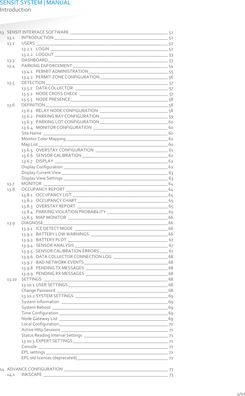
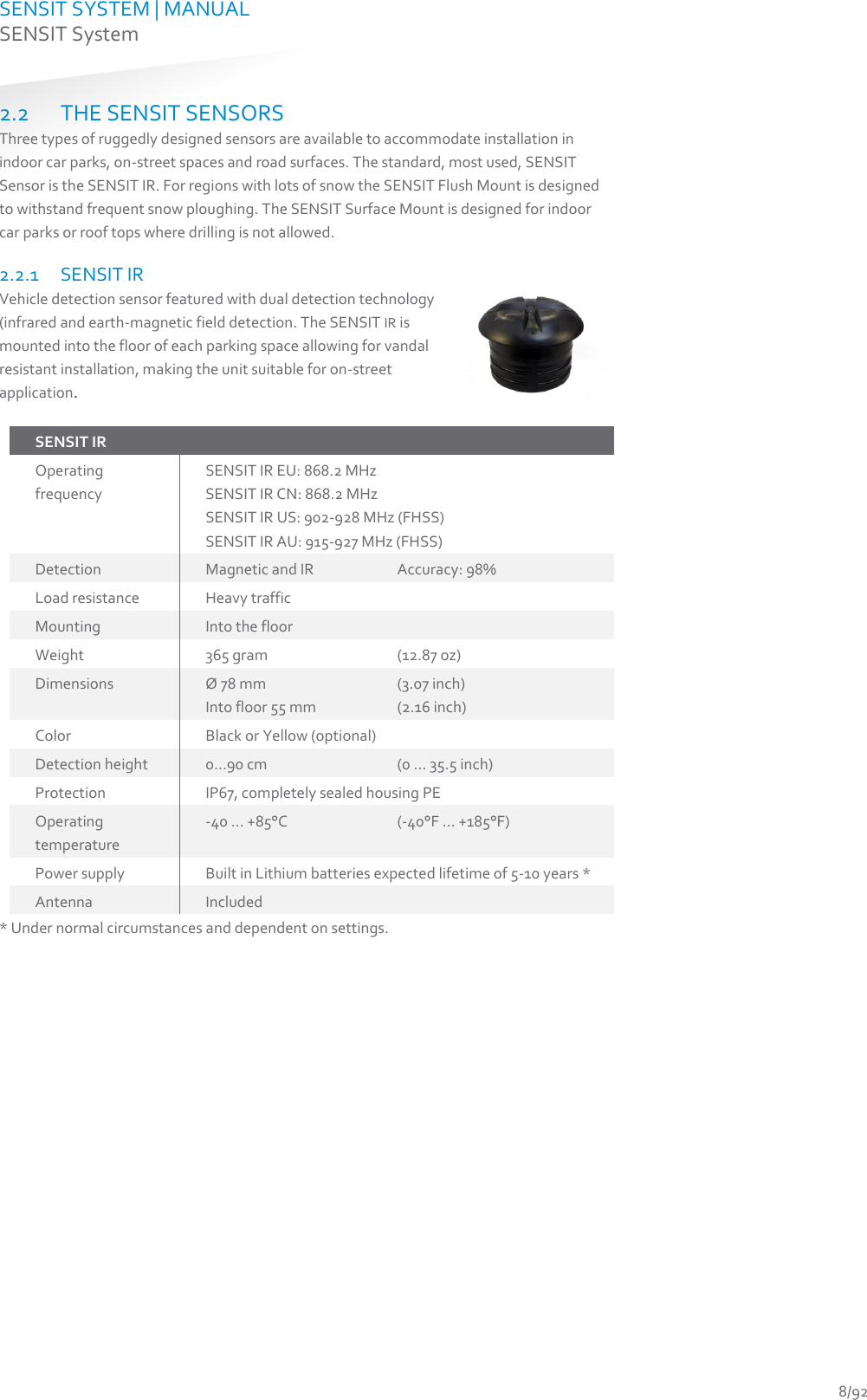
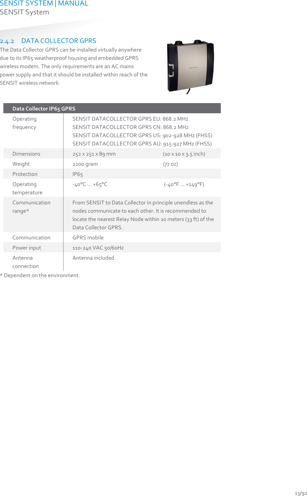
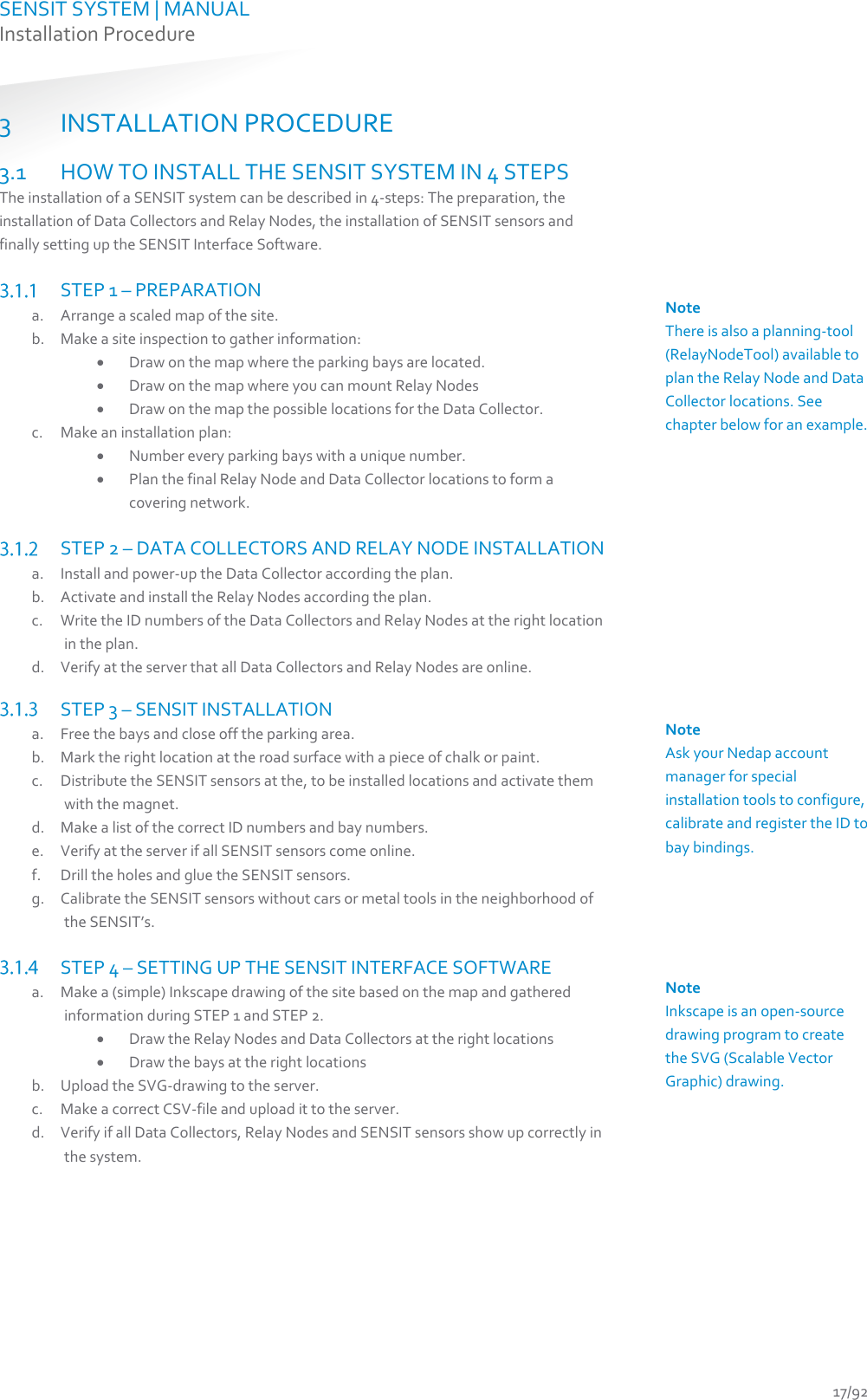
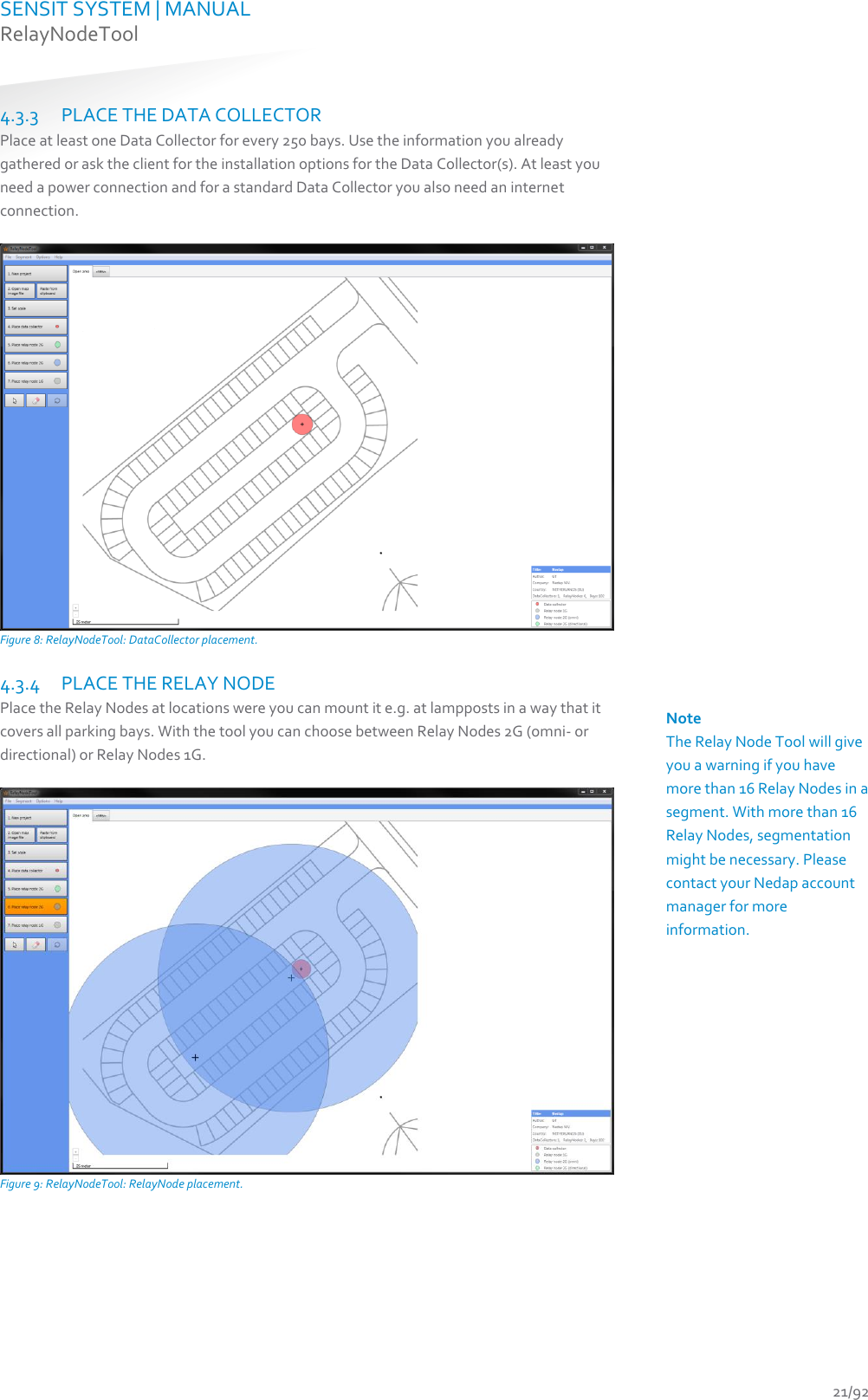
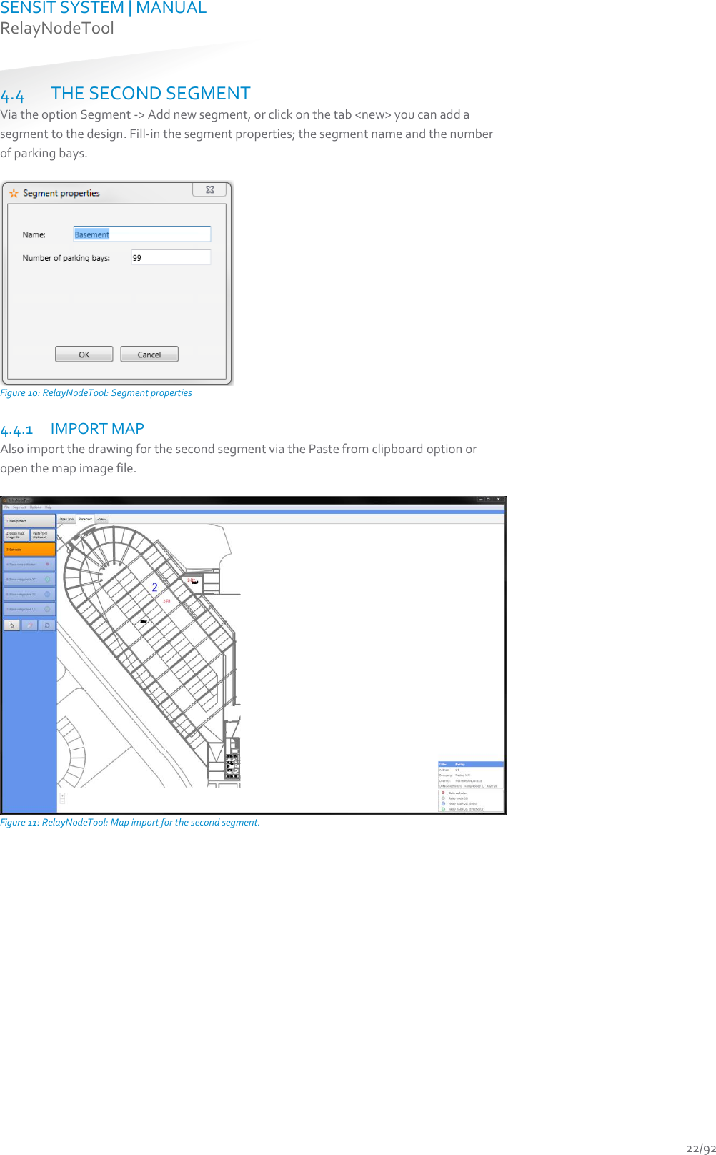
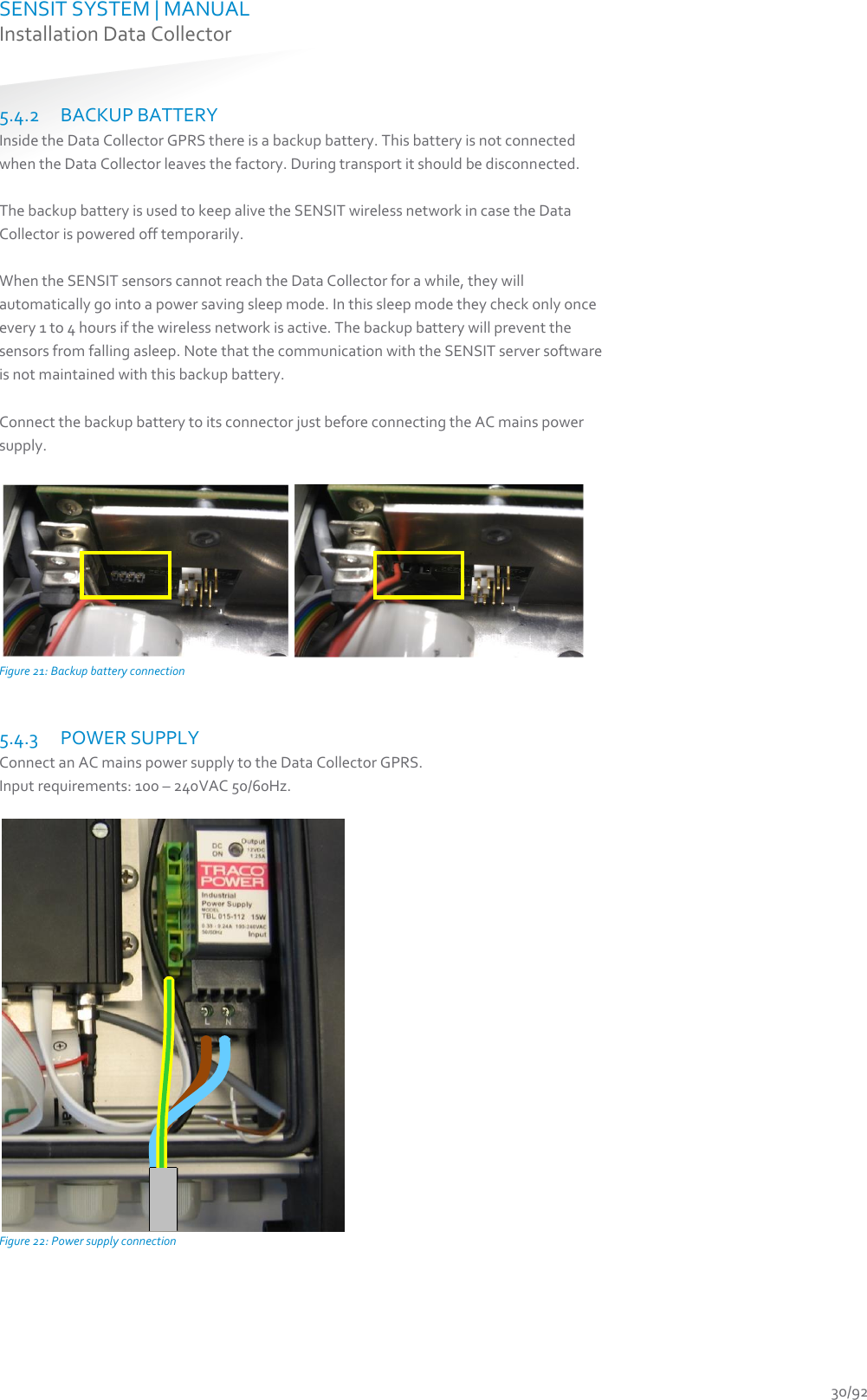
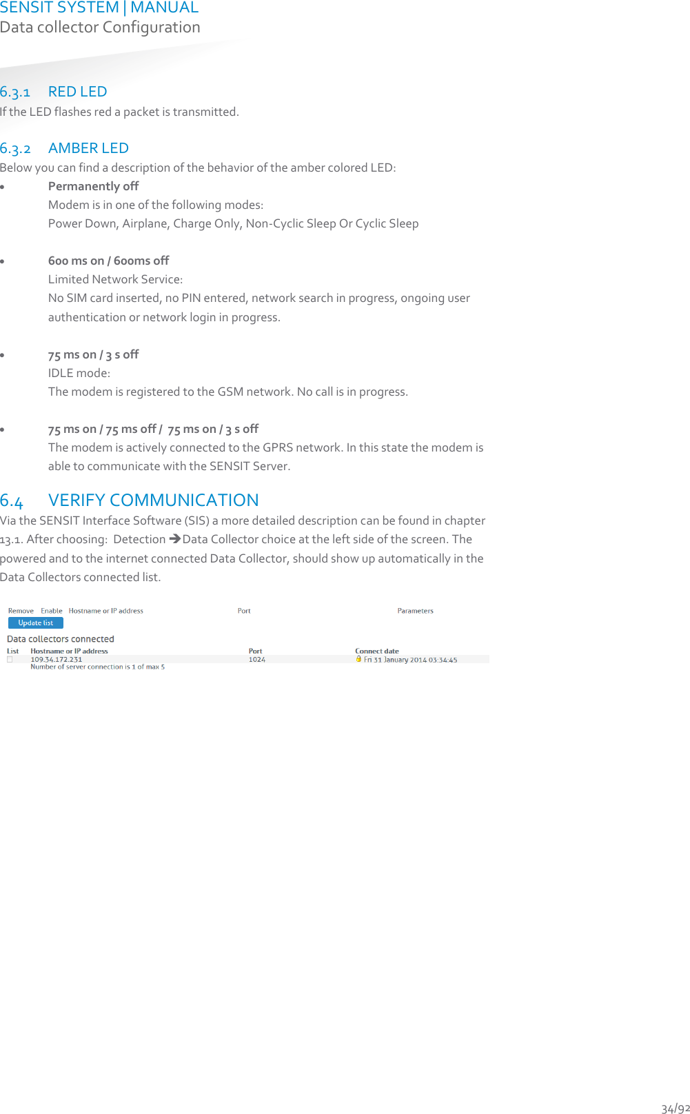
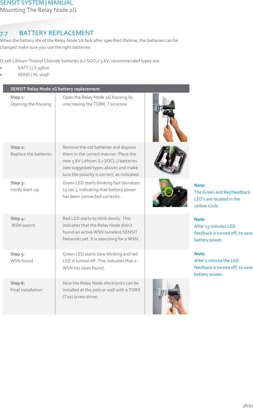
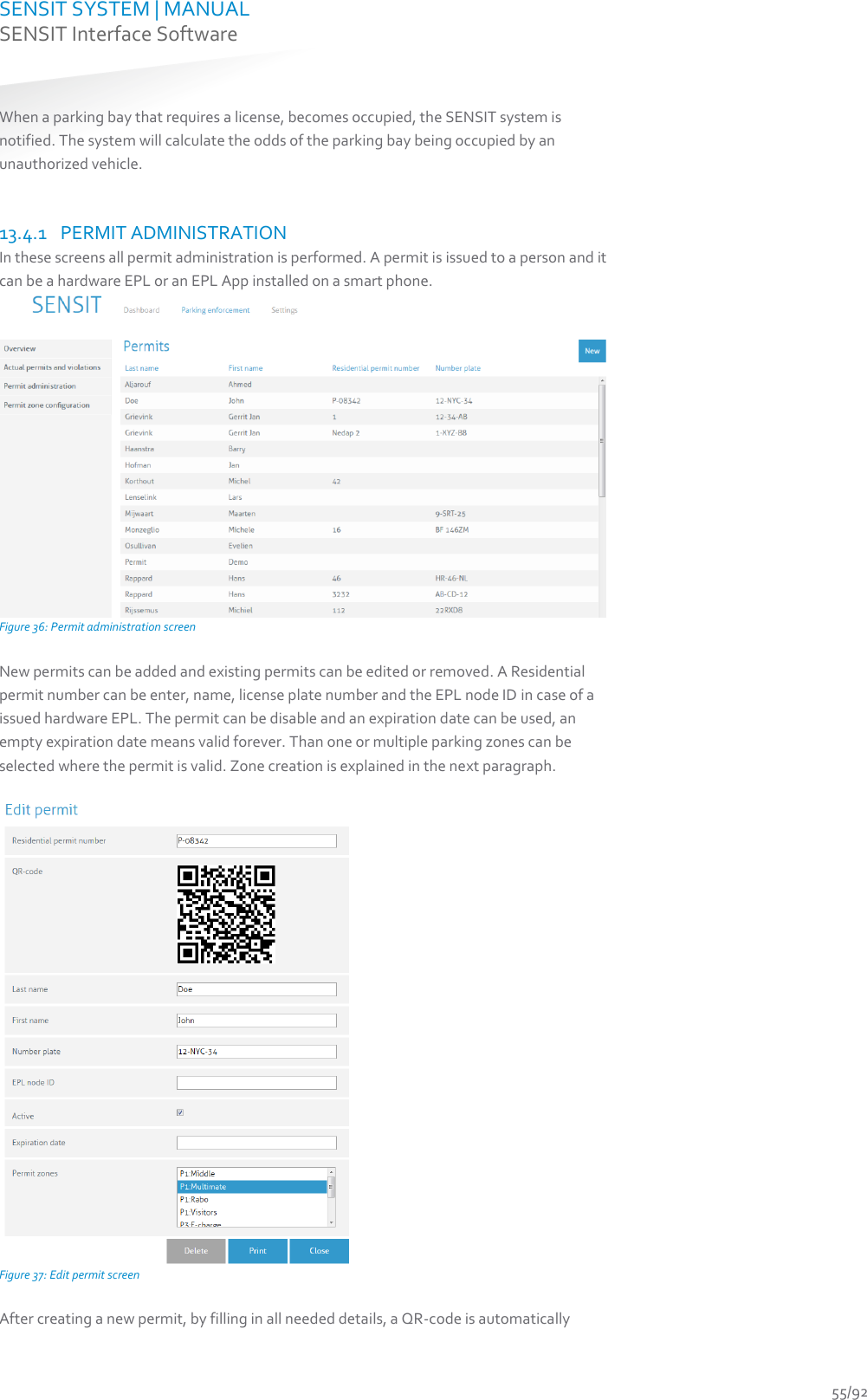
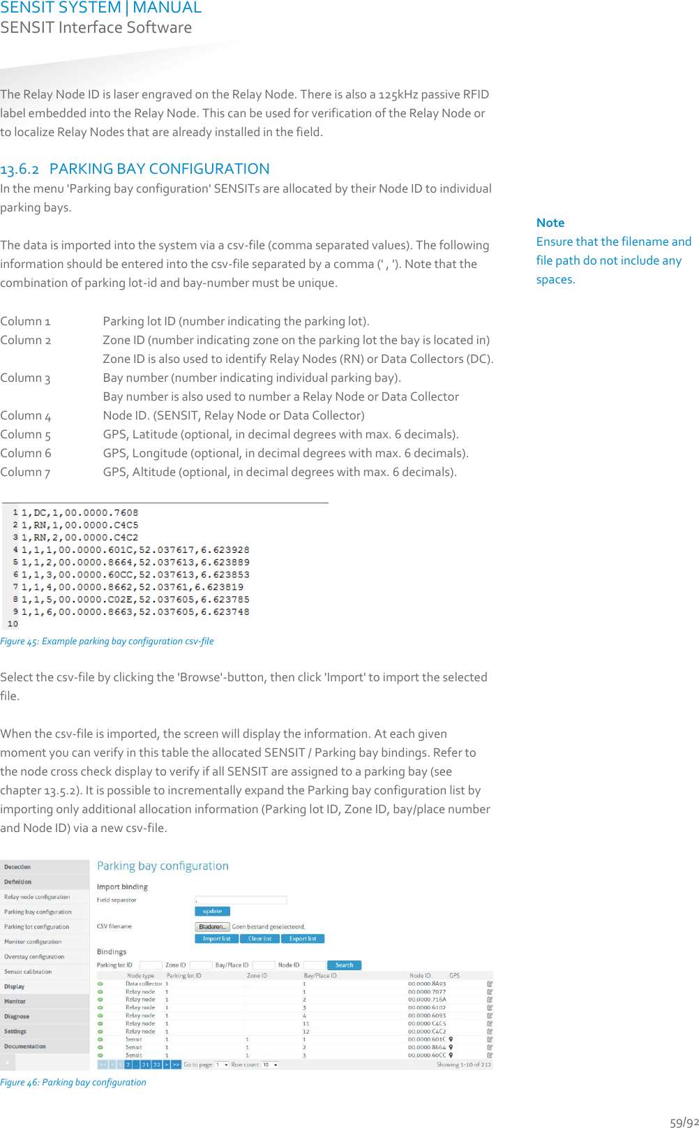
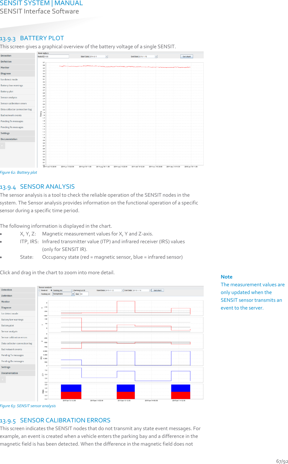
![SENSIT SYSTEM | MANUAL SENSIT System 11/92 2.3 RELAY NODES A Relay Node allows for communication increase and ensures a robust and reliable communication network. It ensures fast transmission of event messages from the vehicle detection sensors to the Data Collector. 2.3.1 SENSIT RELAY NODE 2G The Relay Node 2G is has an improved communication range and a battery lifetime. It ensures a robust and reliable communication network. The Relay Node 2G ensures fast transmission of event messages from the SENSIT sensors to the Data Collector. Relay Node 2G should be mounted preferable at about 3 – 6 meters [10- 20 ft] from the floor (e.g. onto a lamppost) to allow for visible view of the sensors. Relay Node 2G Operating frequency SENSIT RELAY NODE 2G EU: 868.2 MHz SENSIT RELAY NODE 2G CN: 868.2 MHz SENSIT RELAY NODE 2G US: 902-928 MHz (FHSS) SENSIT RELAY NODE 2G AU: 915-927 MHz (FHSS) Weight 540 gram (12.87 oz) Dimensions 200 x 170 x 204 mm (7.87 x 6.69 x 8.03 inch) Mounting Onto a pole, lamppost or wall, mounting bracket included. Mounting height 3 – 6 meters (10 – 20 ft.) Pole dimensions Min. Ø 40 mm (1.57 inch) Max. Ø 150 mm (6 inch) Protection IP65 Operating temperature -40 ... +85°C (-40°F … +185°F) Communication range * DC – RN 2G omnidirectional 35 m (135 ft) DC – RN 2G directional max. 50 m (164 ft) DC GPRS – RN 2G max. 10 m (33 ft) RN 2G – RN 2G max. 100m (328 ft) SENSIT – RN 2G omnidirectional 35 m (135 ft) SENSIT – RN 2G directional 50 m (164 ft) Power supply ** Replaceable Lithium batteries expected lifetime of 5 years Antenna connection Antenna included * Dependent on the environment. ** Under normal circumstances and dependent on settings.](https://usermanual.wiki/Nedap-N-V/SENSITEPL/User-Guide-2688089-Page-11.png)
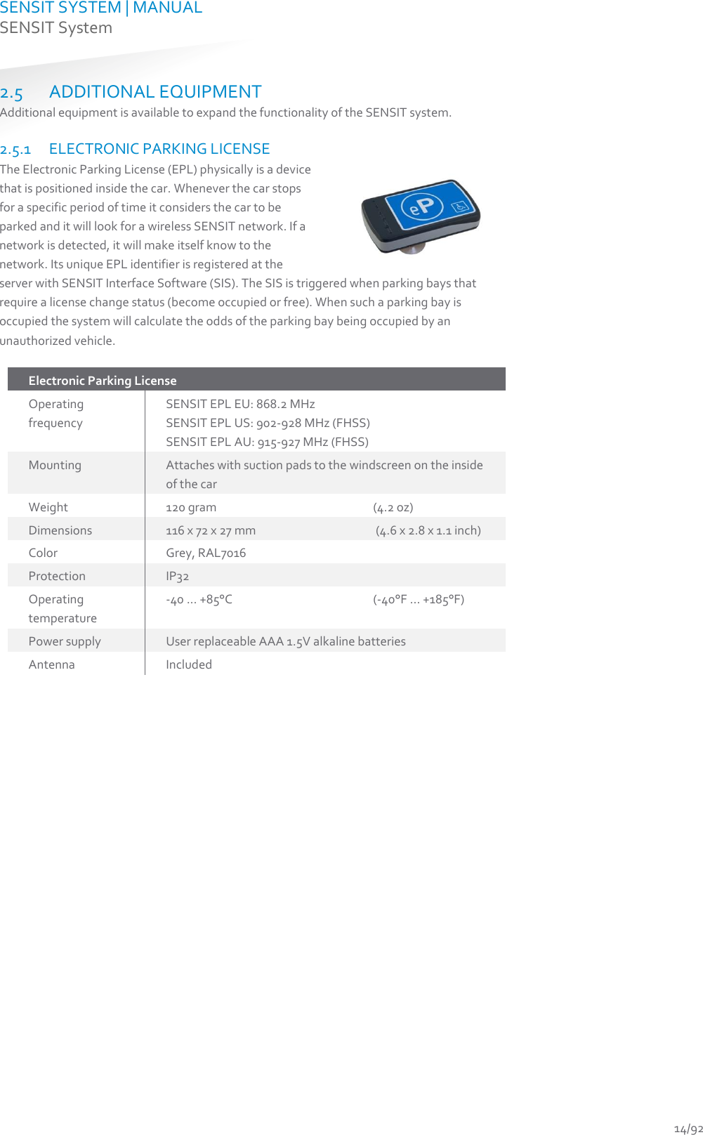
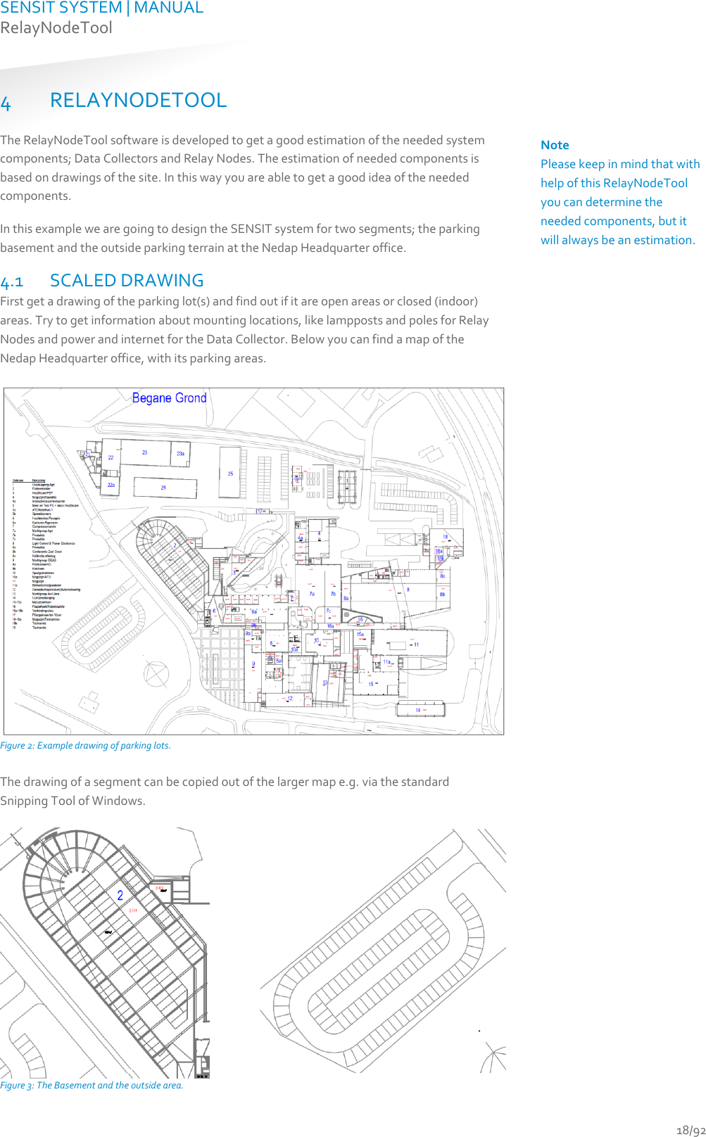
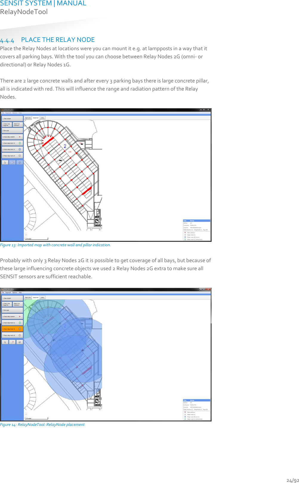

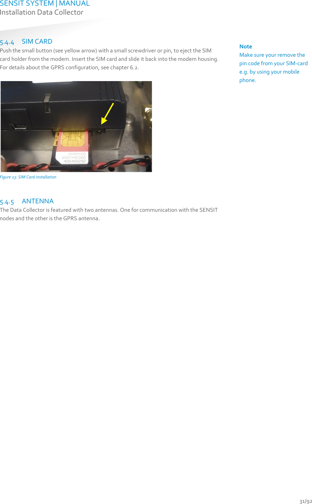
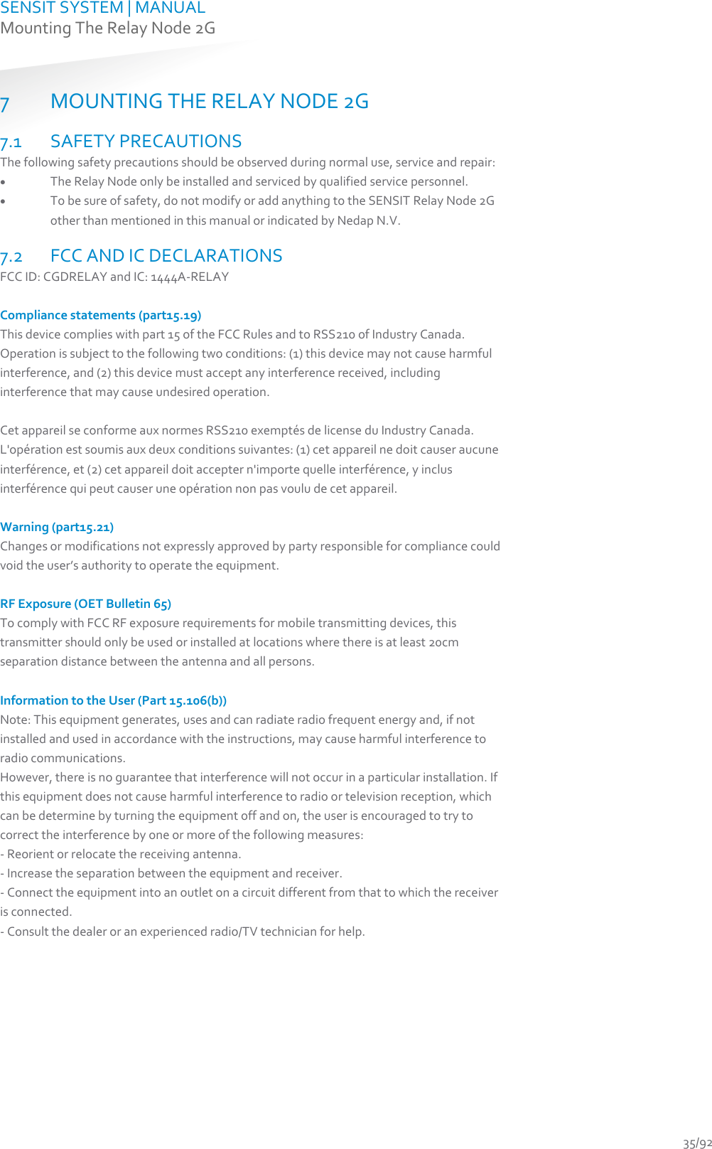

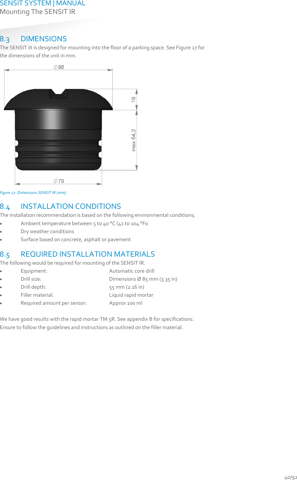
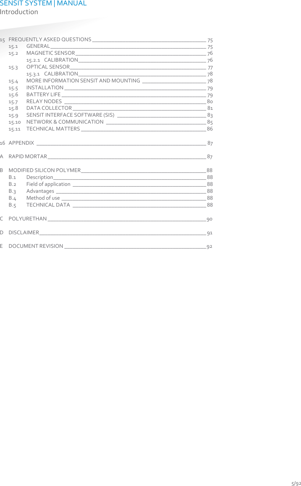
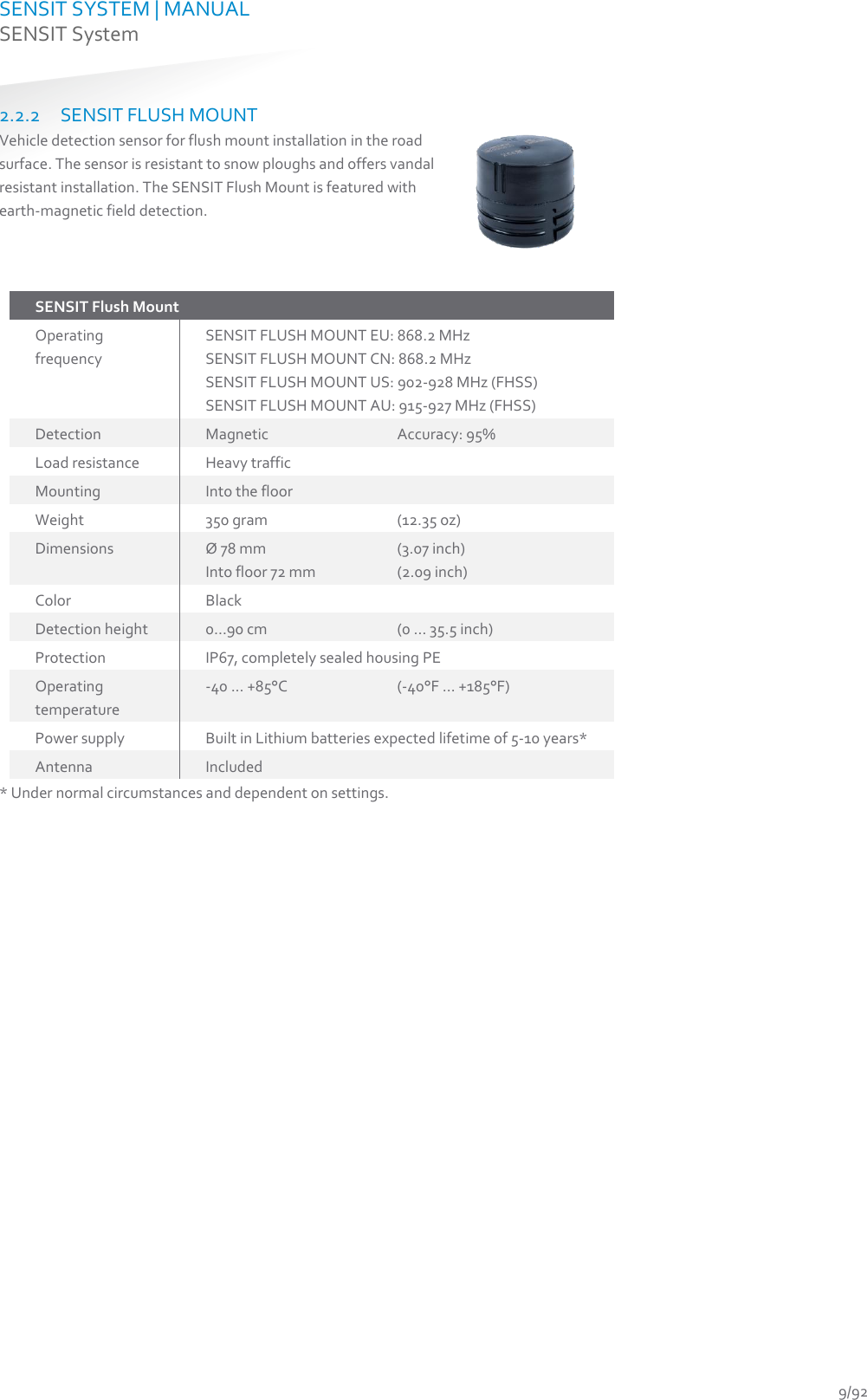
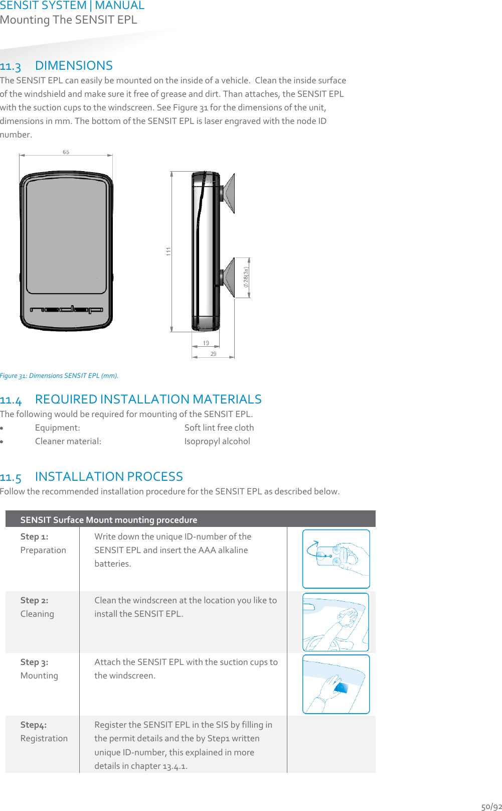
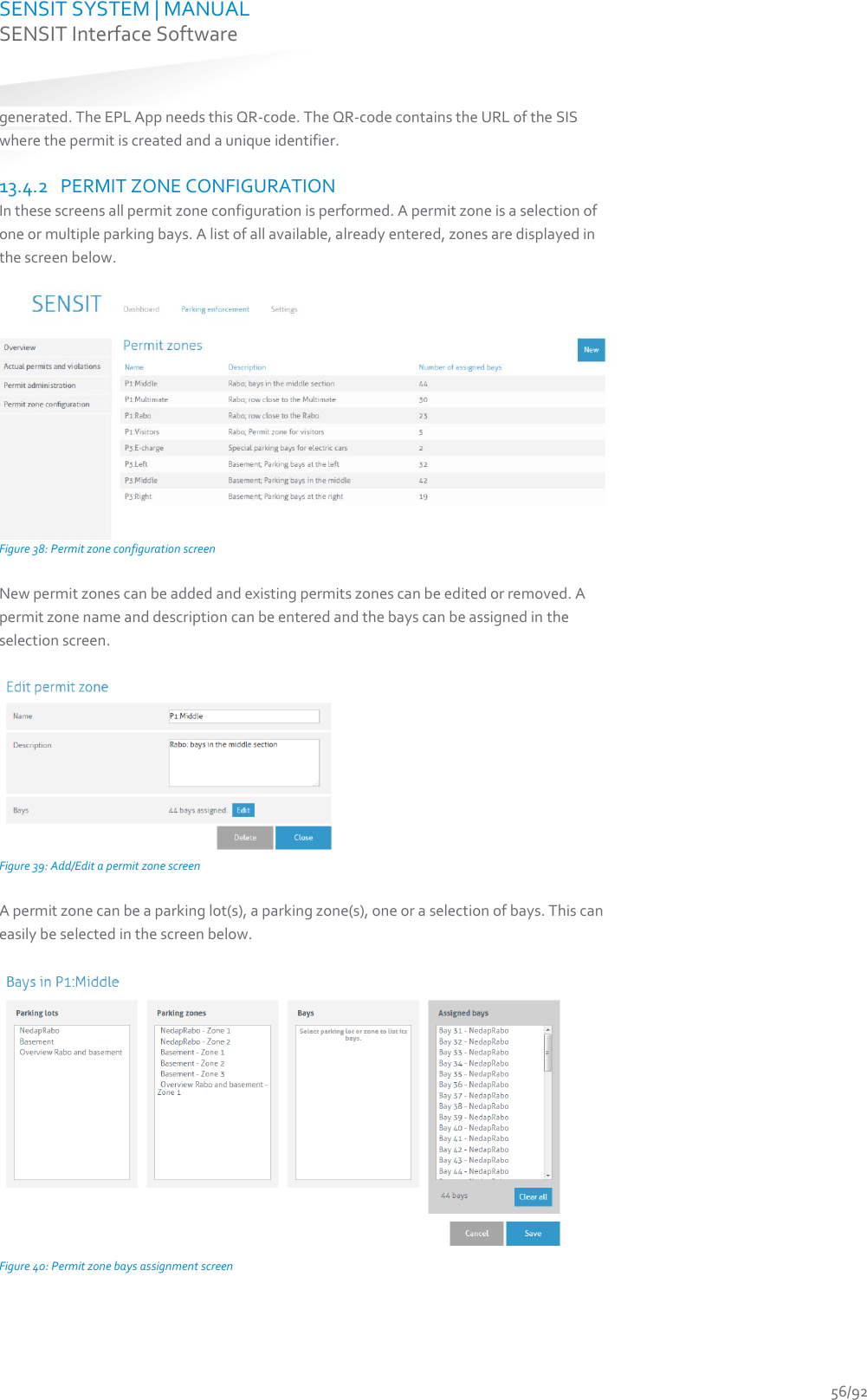
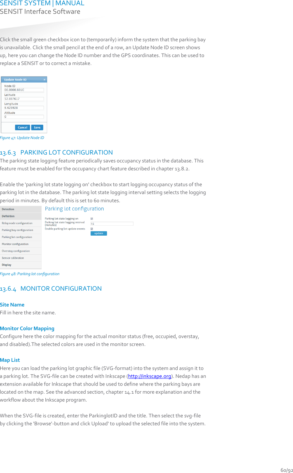
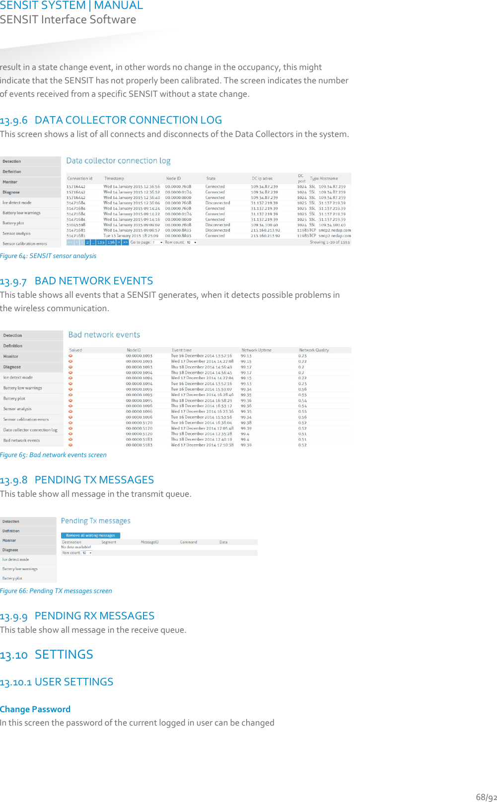
![SENSIT SYSTEM | MANUAL Mounting The SENSIT IR 41/92 8.6 INSTALLATION PROCEDURE Below the mounting procedure for the SENSIT sensor. SENSIT sensor mounting procedure Step 1: Preparation Indicate on the closed parking lot where the SENSIT sensor should be mounted. Distribute the SENSIT sensors over the parking lot and write down the correct ID numbers on your installation plan. Step 2: Drilling Drill a hole of Ø 85 mm [3.35 in] and at least 55 mm [2.16 in] deep into the centre of the parking bay Step 3: Gluing Apply the right amount of filler and pour into the hole. Step 4: Mounting Double-check the node ID number and the parking bay on the installation plan and place the SENSIT sensor into the hole. Step 5: Cleaning-up After mounting the SENSIT sensors in all parking bays or a selection of parking bays. Clean up the parking bays and remove all (metal) tools and objects. Step 6: Activating All SENSIT sensors are set into transport/stock mode during shipment. After installation all mounted SENSIT sensors must be swept with the reset magnet. Step 7: Calibrating After installation the SENSIT sensor must be calibrated. Ensure that the parking space is empty and that there is no car parked on top of the sensor or on neighboring parking bays. SENSIT sensors can be calibrated via the SENIST Interface Software (SIS). See chapter 13.6.6 for more information about calibration. Step 8: Glue curing Leave the filler harden for 8 hours before vehicles are allowed in the parking space again. 8.7 REPLACEMENT When the battery life of the SENSIT IR fails after specified lifetime, we advise to replace the unit completely. The SENSIT IR is fully sealed and for outdoor use, therefore batteries cannot be replaced. Drill out the old SENSIT IR and complete the mounting procedure as describe in the previous paragraph. Ensure to note the node ID number of the SENSIT IR to the parking bay. Update the parking bay configuration list in the SIS software to ensure the new sensor is linked to the right parking bay. Note Take attention that you fixate the SENSIT sensor during the curing time otherwise the sensor will start to float. Note Once out of the transport/stock mode the battery lifetime starts to count. Note When the SENSIT sensors are not calibrated they hardly send any messages. This is due to the fact that there are no events generated because the magnetic thresholds are not crossed.](https://usermanual.wiki/Nedap-N-V/SENSITEPL/User-Guide-2688089-Page-41.png)
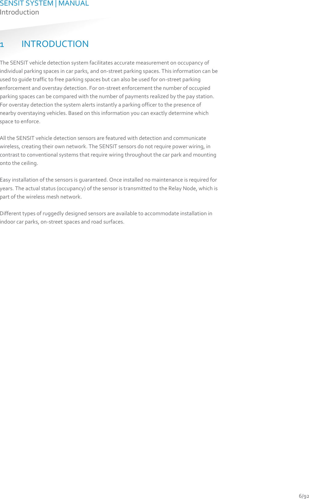
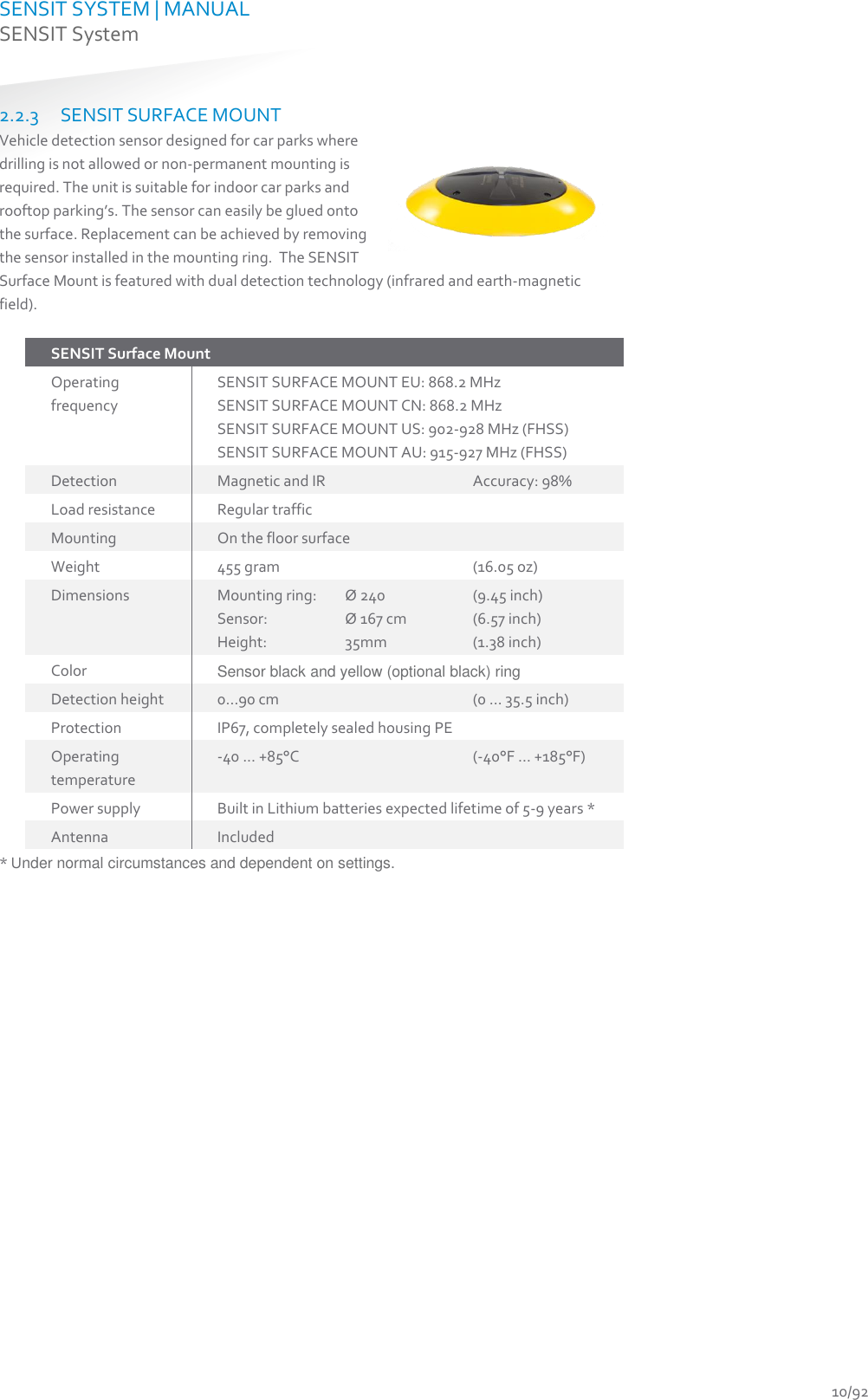
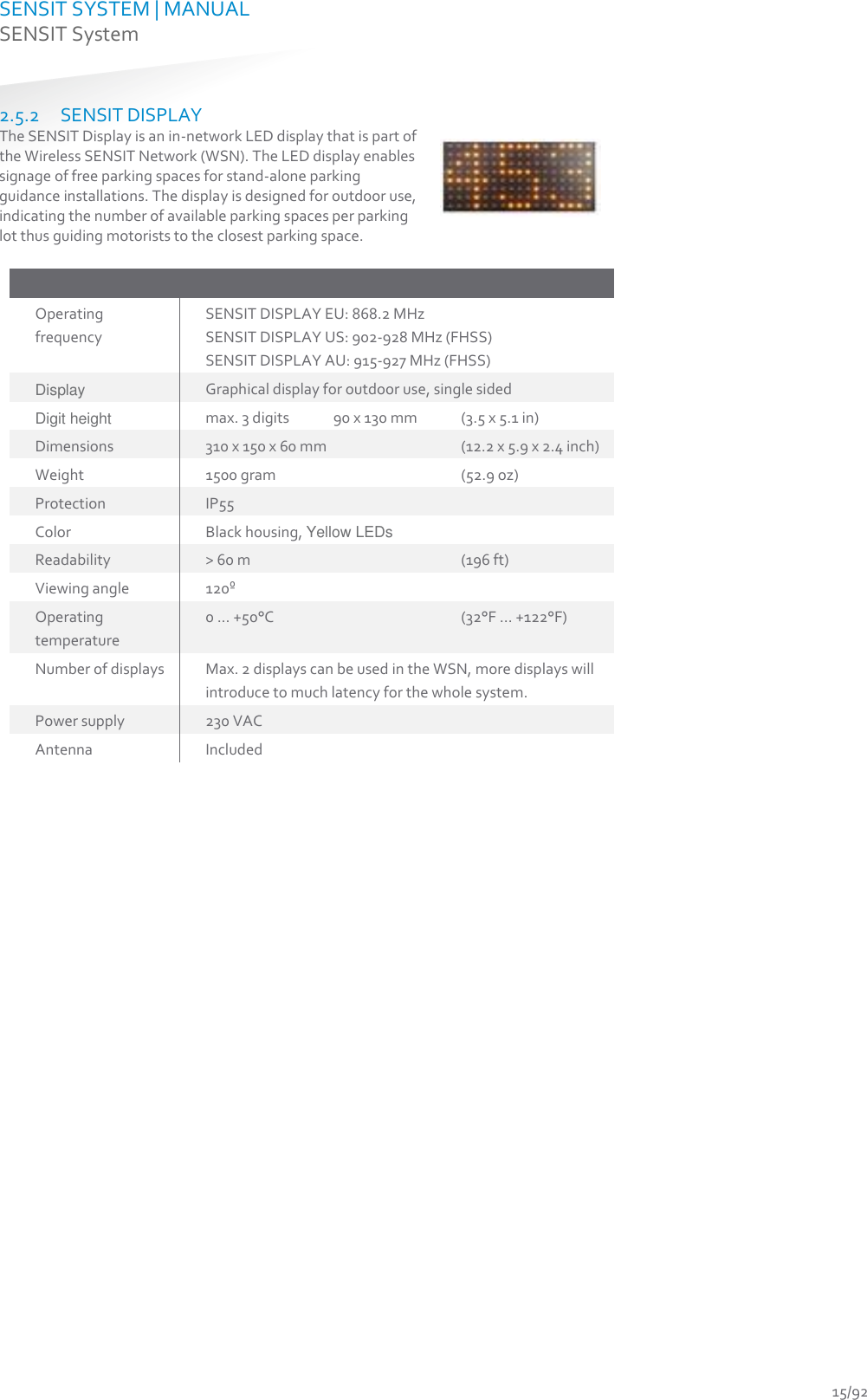
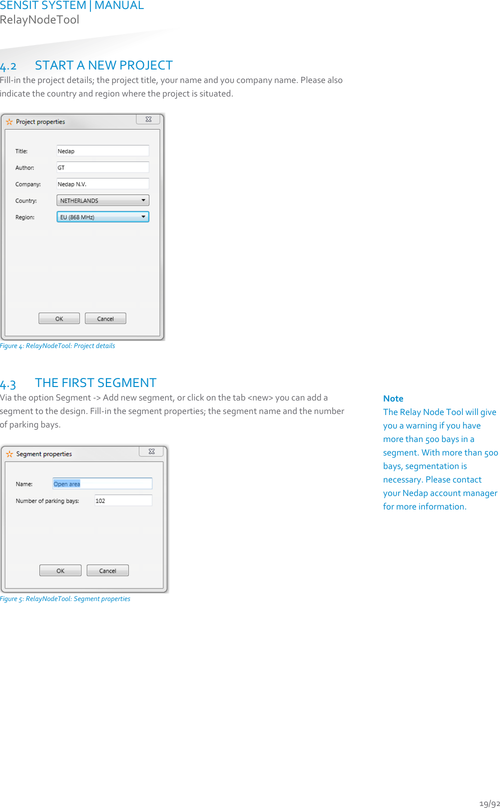
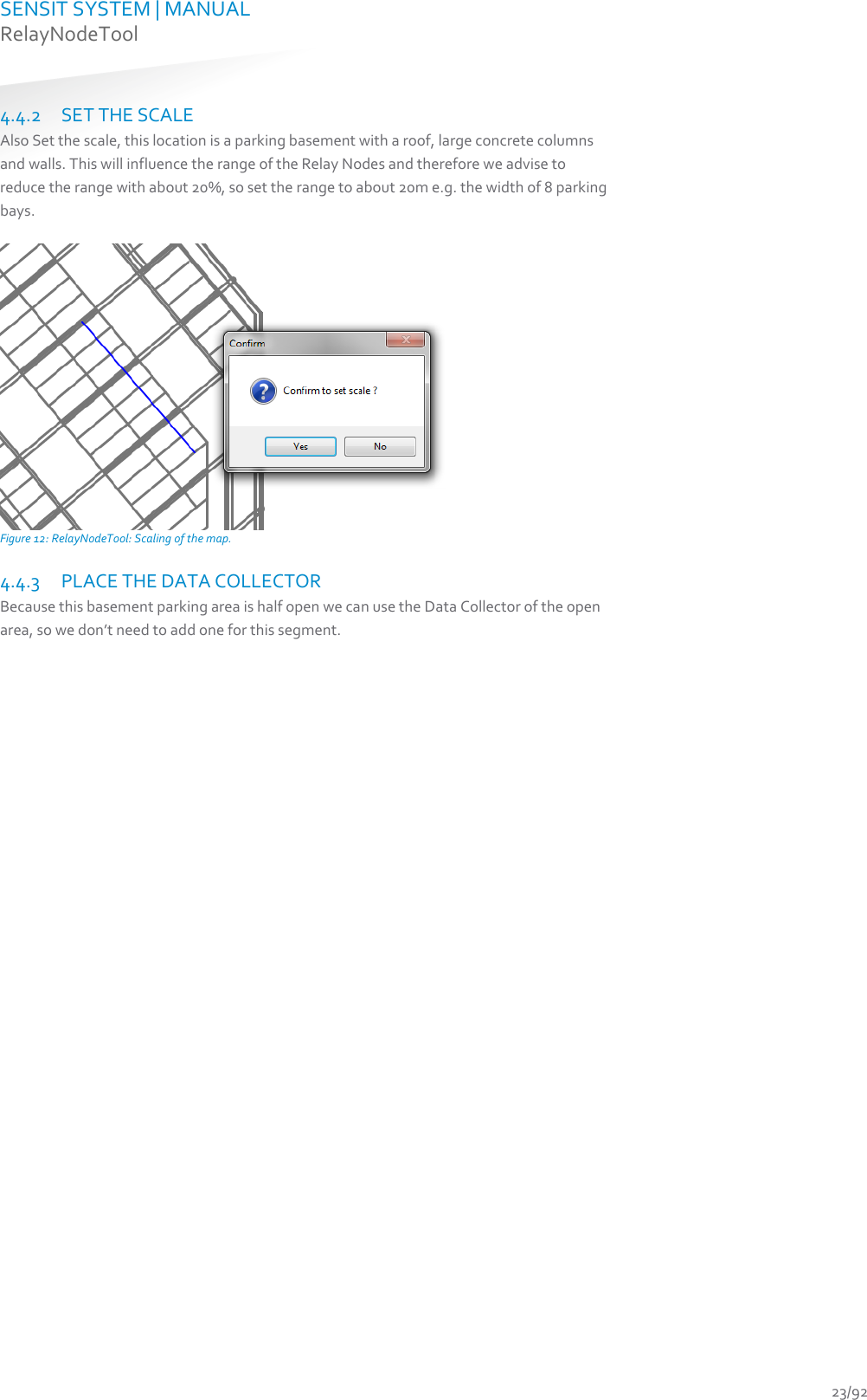
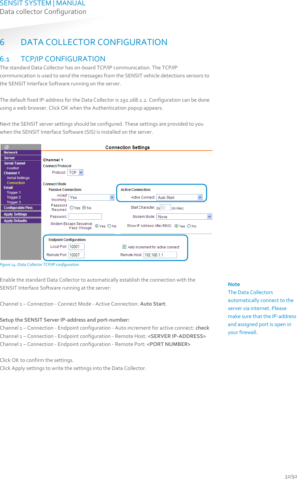
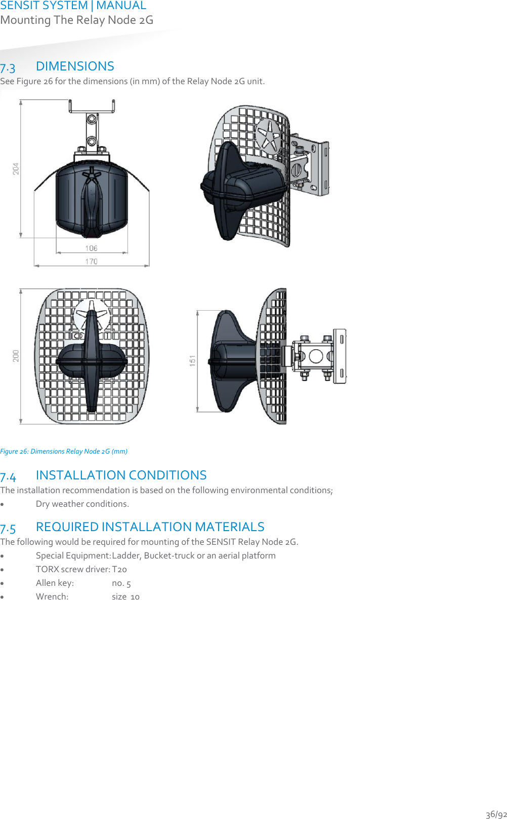
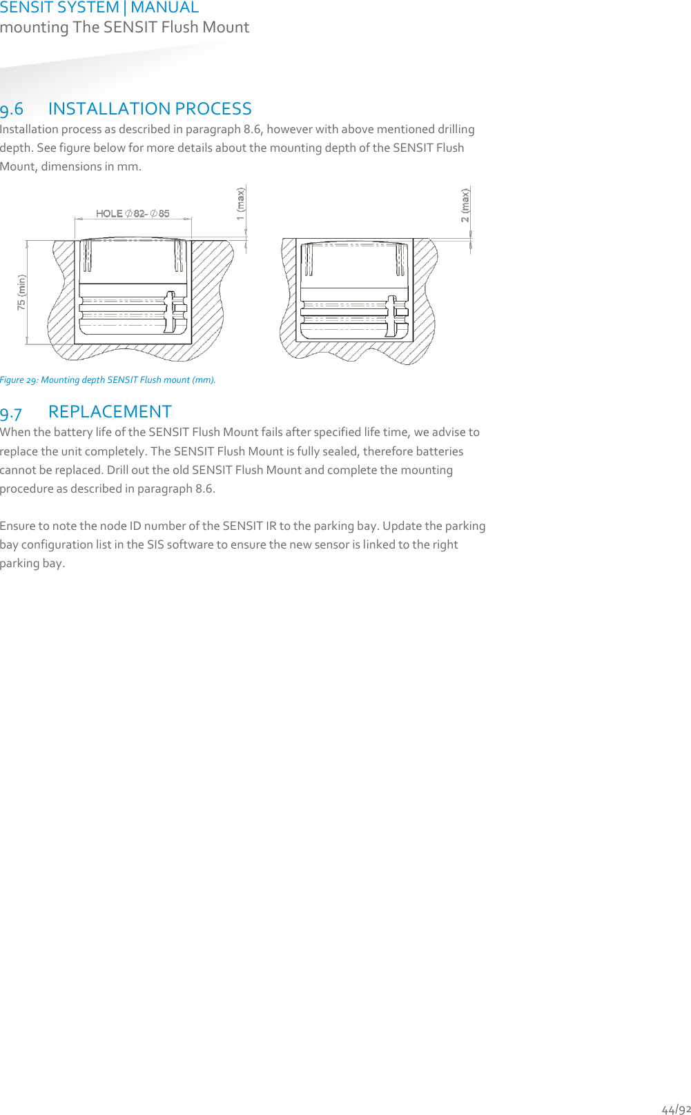
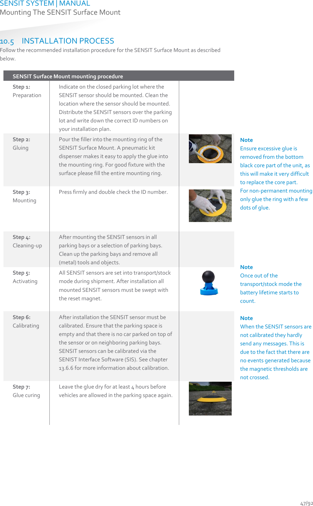
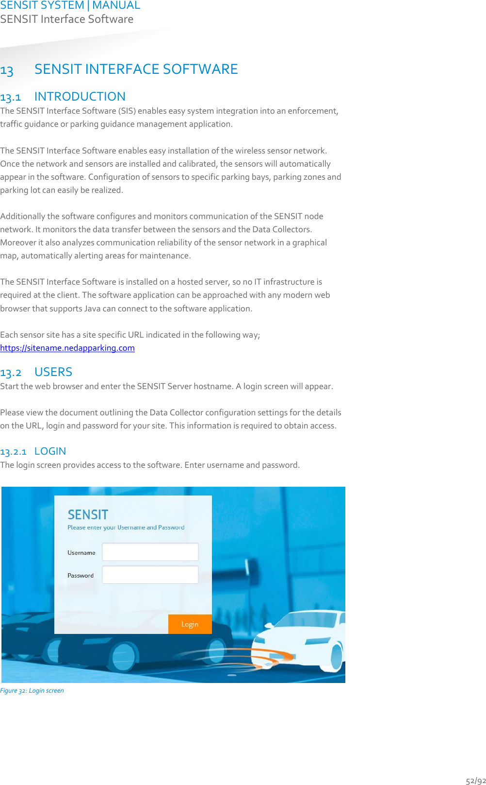
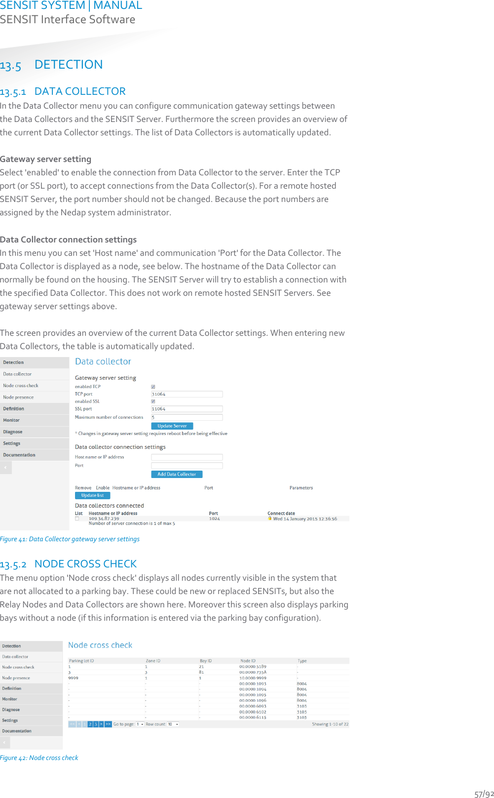
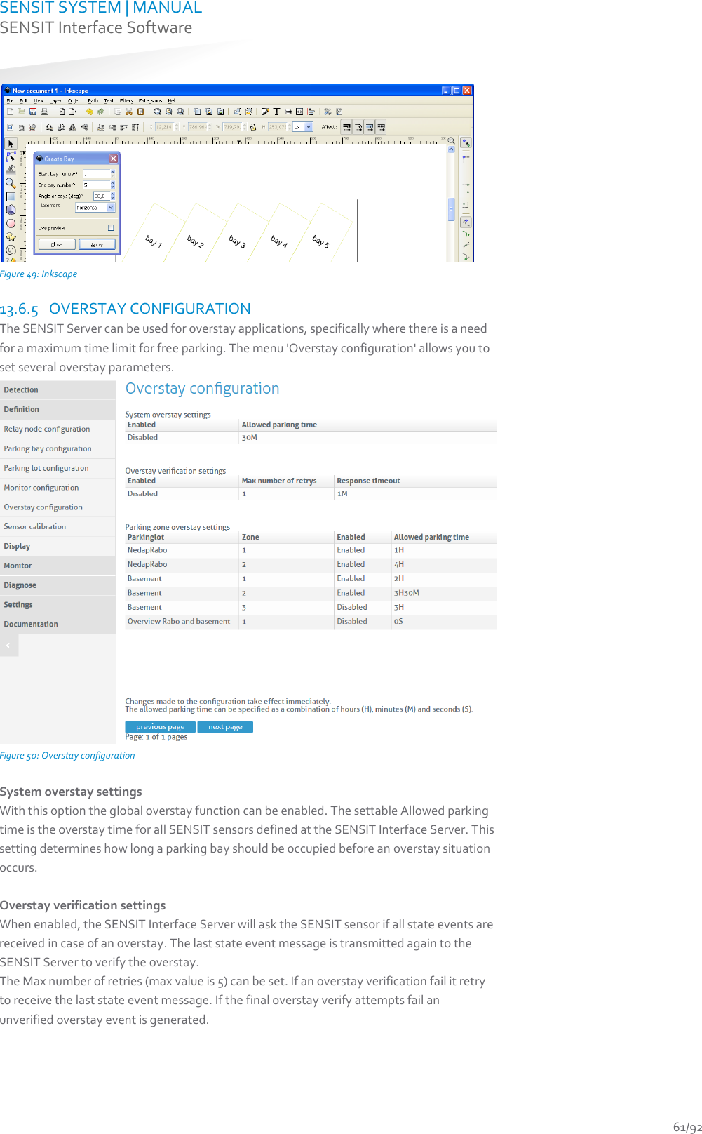
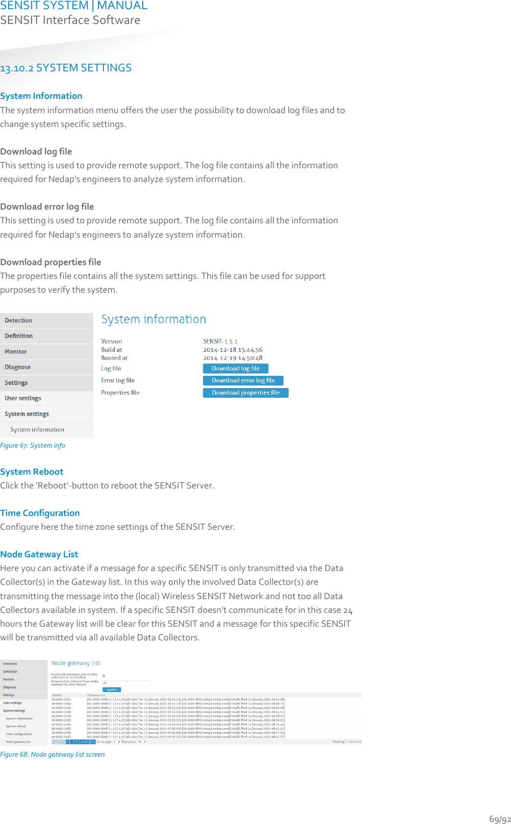
![SENSIT SYSTEM | MANUAL mounting The SENSIT Flush Mount 43/92 9.3 DIMENSIONS The SENSIT Flush Mount is designed for full mounting into the floor of a parking space. As the unit is fully flush with the road surface the unit is snow plough resistant. The SENSIT Flush Mount is only featured with magnetic detection. See Figure 28 for the dimensions of the unit in mm. The top of the SENSIT Flush Mount is laser engraved with the node ID number. Figure 28: Dimensions SENSIT Flush mount (mm). 9.4 INSTALLATION CONDITIONS The installation recommendation is based on the following environmental conditions; Ambient temperature between 5 to 40 °C [41 to 104 °F] Dry weather conditions Surface based on concrete, asphalt or pavement 9.5 INSTALLATION MATERIAL The following would be required for mounting of the SENSIT FLUSH MOUNT. Equipment: Automatic core drill Drill size: Dimensions Ø 85 mm (3.35 in) Drill depth: 75 mm (2.95 in) Filler material: Liquid concrete mortar Required amount per sensor: Approx. 100 ml We have good results with the rapid mortar TM 5R. See appendix B for specifications. Ensure to follow the guidelines and instructions as outlined on the filler material.](https://usermanual.wiki/Nedap-N-V/SENSITEPL/User-Guide-2688089-Page-43.png)


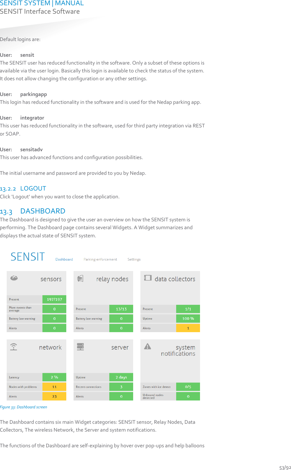
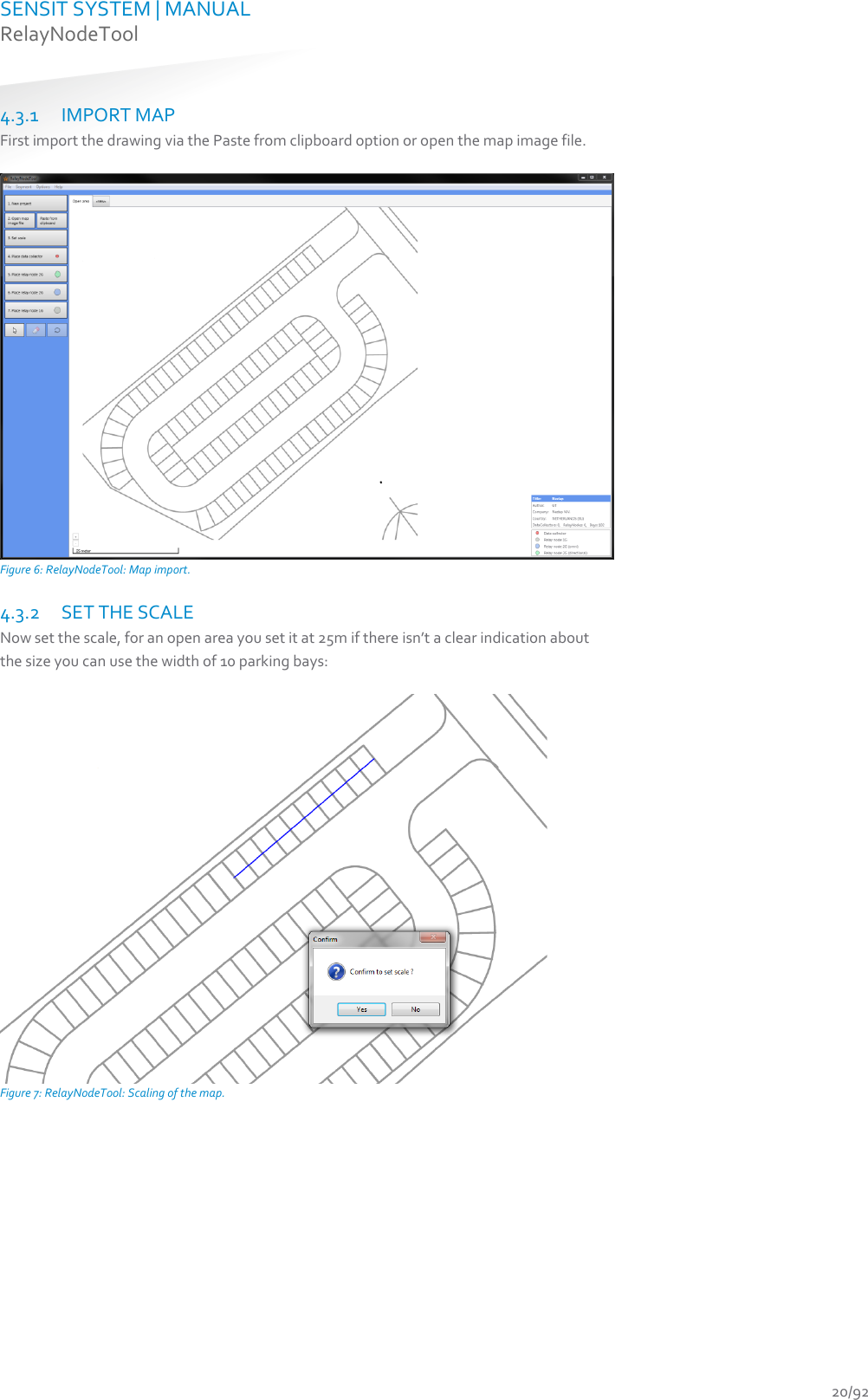
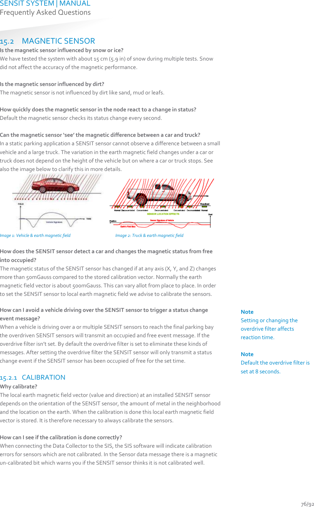
![SENSIT SYSTEM | MANUAL Frequently Asked Questions 75/92 15 FREQUENTLY ASKED QUESTIONS 15.1 GENERAL What types of SENSIT sensors are available and what is the difference? There are 3 different types of SENSIT sensors available: 1 SENSIT IR - Magnetic and optical sensor suitable to be built-into the floor of each parking space. 2 SENSIT Flush Mount - Magnetic sensor suitable to be built-into the floor of each parking space. 3 SENSIT Surface Mount - Magnetic and optical sensor for mounting onto the floor of a parking space What is the accuracy of the SENSIT Flush Mount? The magnetic sensor can achieve an accuracy of 95%. What is the accuracy of the SENSIT IR and SENSIT Surface Mount? The combination of the magnetic and optical sensor has an average accuracy of above 98%. How scalable is the SENSIT system? The SENSIT system is quite scalable. The theoretical maximum number of SENSIT nodes in one network is about 65000. In general, large installation need to be divided into smaller sub-networks (segments), which makes it better manageable and easier to understand. Sites that have more than 500 sensors or more than 15 Relay Nodes need segmentation. Please contact your Nedap account manager. What is the temperature range for the SENSIT and SENSIT IR? The temperature range for both SENSIT as well SENSIT IR is -40°C to 85°C [-40 to 185°F]. Temperatures below -30°C [-22°F] might affect accuracy of the magnetic sensor. The accuracy on the optical sensor remains unchanged. How does the energy efficient Wireless SENSIT Network work? The medium access protocol is based upon time division multiple access (TDMA). Time is divided into time slots, which (Relay) nodes can use to transfer data without having to content for the medium or having to deal with energy wasting collisions of transmissions. After the frame length, which consists of 16 time slots, the (Relay) node again has a period of time reserved for it. We have parameterized the duration of a time slot and the number of time slots. The default timeslot is 100ms and the number of timeslots in a frame is 16. In the US the system uses also Frequency Hop Spread Spectrum (FHSS); a pseudo random frequency hopping scheme every timeslot the SENSIT also changes the frequency. In this way the devices comply with FCC regulations. If a SENSIT sensor decides to transmit a messages it asks the first Relay Node within reach if it is allowed to transmit a message to this Relay Node, if allowed the Relay Node will receive the message from the SENSIT and retransmits this message to the next Relay Node or directly to the Data Collector. Can a SENSIT sensor been used to replace a loop detector? The SENSIT sensor is designed to detect a changes in either optical or earth magnetic field. A continuous flow of traffic would generate a constant status change. Moreover since the system is based on wireless communication, communication is slower compared to hard wired loop. We therefore do not advise to use the SENSIT sensor to replace safety loops for critical applications.](https://usermanual.wiki/Nedap-N-V/SENSITEPL/User-Guide-2688089-Page-75.png)
![SENSIT SYSTEM | MANUAL Frequently Asked Questions 78/92 What happens in case of sandstorms, when the optical sensor is covered? When the optical is covered with sand the sensor cannot detect reflections of a vehicle that parks over the SENSIT sensor. So the optical sensor will indicate a free bay, the secondary (magnetic) sensor will detect the movement of the different cars above the SENSIT sensor. After a few (default: 10) mismatches between the continuous occupied optical sensor and the magnetic sensor the final status will be indicated by the magnetic sensor. As soon as the optical sensor is clean, the SENSIT sensor will automatically switch back to optical detection again. Is the SENSIT IR affected by direct sun light? Normally the optical IR sensor is not affected by sunlight. Only at locations close to the equator when the sun is directly above the SENSIT IR the optical sensor can give an overexposure alert, which will indicate a free bay. 15.3.1 CALIBRATION What is the maximum range of the optical sensor? The IR reflection depends very much on the reflection coefficient of surface it radiates at. Ceilings of over 3 meters (9 feet) are seen by the optical sensor. You can set the sensitivity of the optical sensor when applying the sensors for indoor applications. Can the optical sensor been used indoors? The optical sensor can be used indoors, for this the IR transmitting power needs to be adjusted (calibrated) to avoid the unit from detecting the ceiling. 15.4 MORE INFORMATION SENSIT AND MOUNTING What filling material should I use? The best way to fix the SENSIT sensors into the floor of the parking space is using rapid mortar (eg.TM 5R). Ensure to fixate the SENSIT sensors during curing time, to avoid them from floating in the mortar. When you want to use another brand of rapid mortal please sent us the datasheet so we can analyze this and advise you on use. Is a SENSIT IR snow plough resistant? When using the SENSIT IR in environments with snowy weather conditions, we advise to set a tolerance on the snow plough of 2 cm [0.78 in] to ensure the top of the sensor is not damaged by the snow plough. The SENSIT IR is not fully snow plough resistant; however it can withstand a few incidental hits. The SENSIT Flush Mount is snow plough resistant and can be used in areas with frequent snow conditions, at the cost of a bit lower accuracy.](https://usermanual.wiki/Nedap-N-V/SENSITEPL/User-Guide-2688089-Page-78.png)
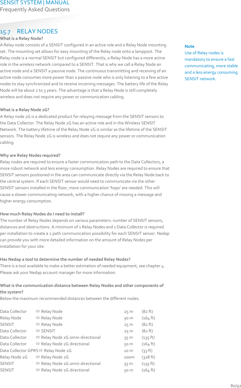
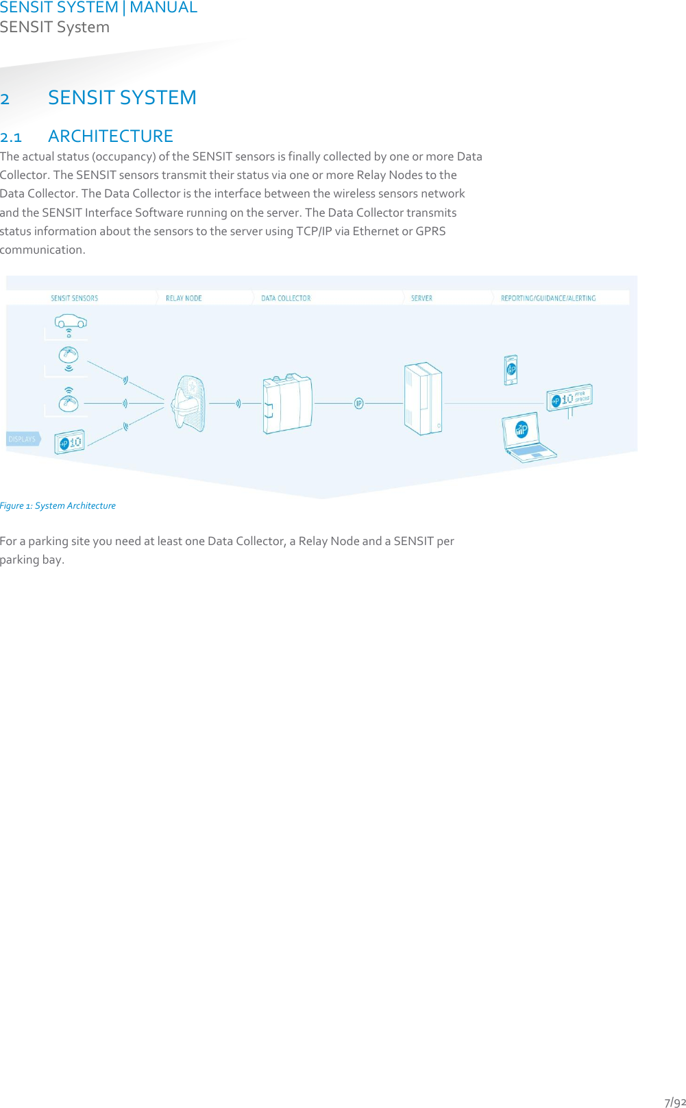
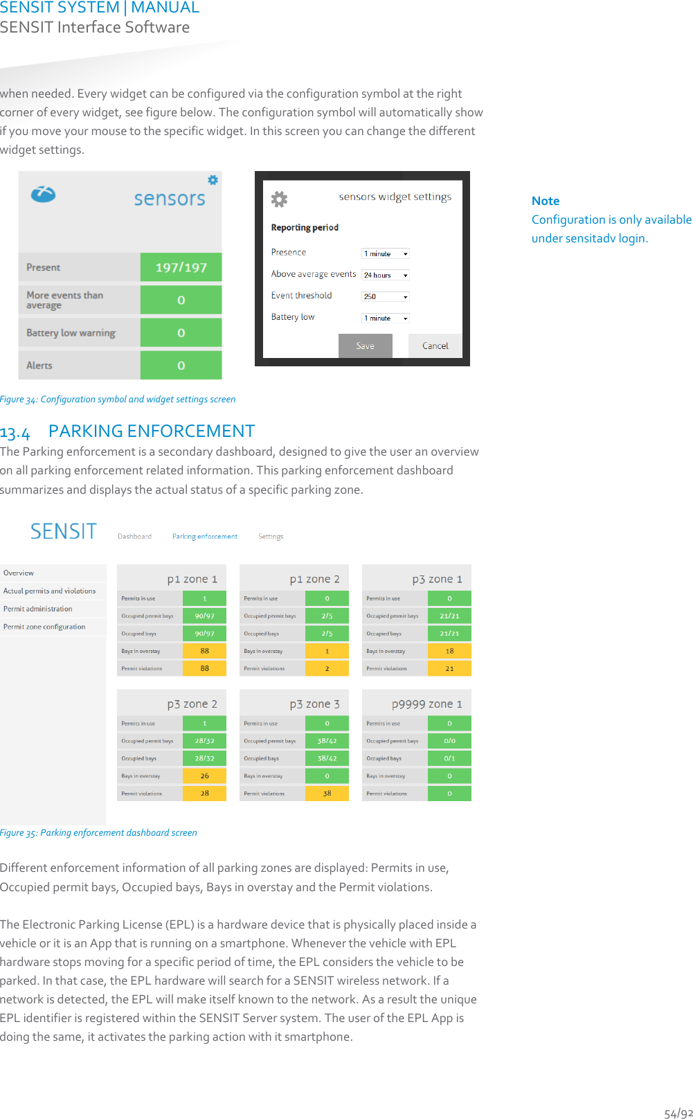
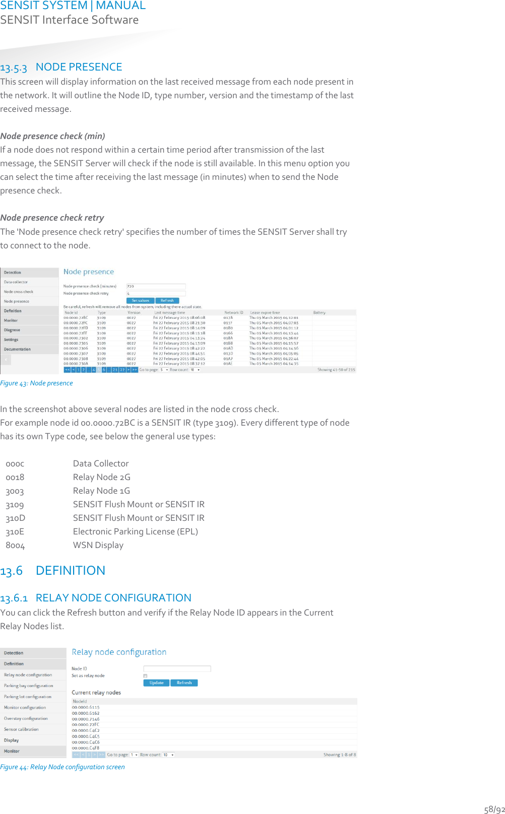
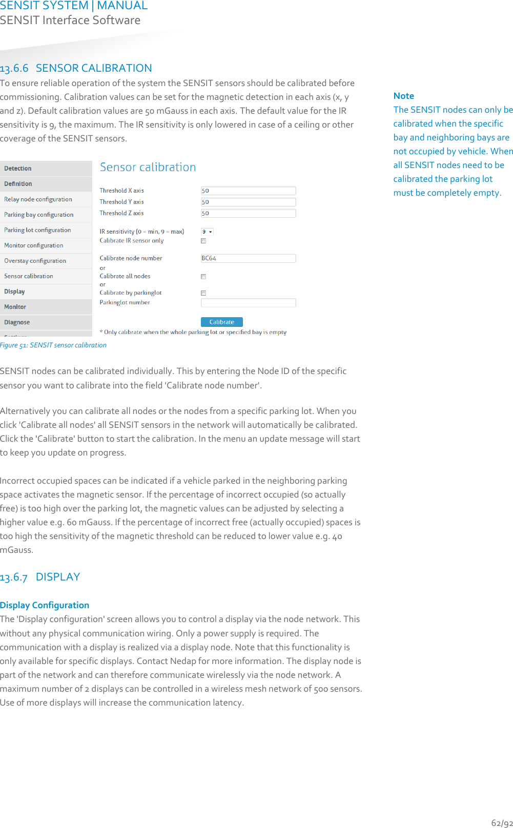
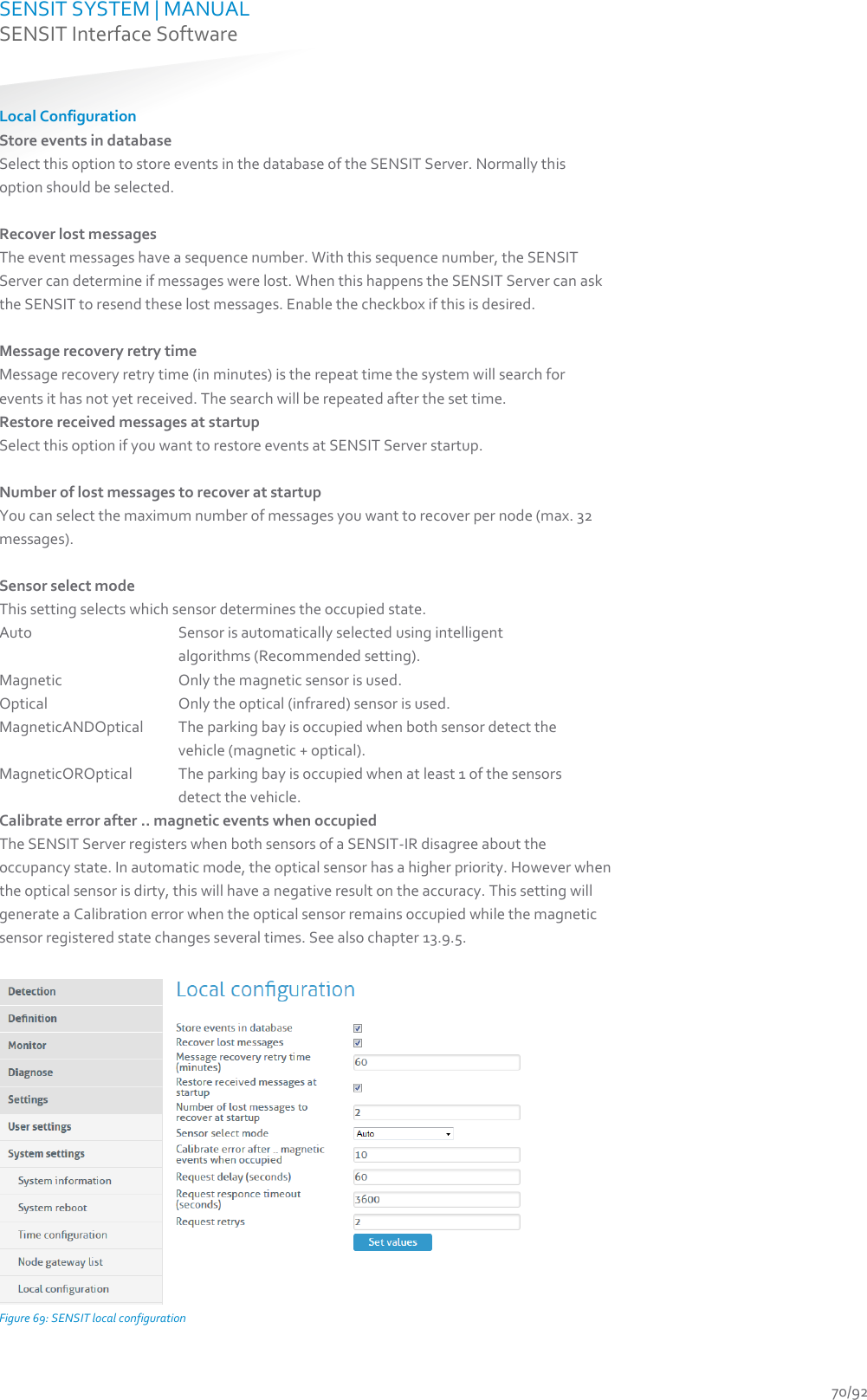
![SENSIT SYSTEM | MANUAL Frequently Asked Questions 81/92 How do I replace a Relay Node? After end of battery life, the SENSIT can easily be taken out of the Relay Node mounting set. Only the SENSIT sensor configured as Relay Node would need to be replaced. The batteries of a Relay Node 2G can be replaced, see chapter 7.7. Can the Relay Nodes also be used for indoor car parks? Yes, the Relay Nodes can also be used for indoor car parks, see also picture below. Indoor car parks might require more Relay Nodes due to mounting height restrictions and influence of concrete on communication. 15.8 DATA COLLECTOR What is the Data Collector? The Data Collect is the central unit which collects the events from SENSIT sensors via the Relay nodes and transmits this information to the host system or SENSIT Interface Software. Can I implement data from the Data Collector directly? No, this feature is not supported and subject to change. For easy integration we advise to use the SENSIT Interface Software. What is the most critical part of the SENSIT system? The most critical part is the Data Collector when the power of the Data Collector is interrupted or if the Data Collector is damaged the whole Wireless SENSIT Network will stop working. Only with a good and powered Data Collector the wireless network will start. By using an UPS, (short) power failure can be solved. Where do I mount the Data Collector? The Data Collector can be installed within 25 m [84 ft] from the first SENSIT node or Relay Node. Be sure not to position the Data Collector in a metal enclosure as it will block the RF communication. The Data Collector can be mounted in a plastic housing, which is transparent for RF signals. How can we make the Data Collector useable outdoors? The standard Data collector can be placed in a plastic housing suitable for outdoor use. An outdoor box which is made of a conduction material or contains a lot of conduction material can create some problems as it blocks RF communication. A better solution is to use the Data Collector GPRS it has IP65 housing. What power wiring (cable specs) do I need for the standard Data Collector? Power: 100-240 VAC, 50-60 Hz, 180mA, Power input: 5 VDC, max 1A Power consumption: 5VA Communication between Data Collector and SIS: Ethernet Cat 5 E](https://usermanual.wiki/Nedap-N-V/SENSITEPL/User-Guide-2688089-Page-81.png)