Nedap N V SENSITSM SENSIT SURFACE MOUNT User Manual SENSIT
N. V. Nederlandsche Apparatenfabriek NEDAP SENSIT SURFACE MOUNT SENSIT
UserManual.wiki
>
Nedap N V
>
SENSITSM User Manual
14_SENSIT_InstallGuide_E CGDSENSITSM
Navigation menu
Upload a User Manual
Namespaces
Wiki Guide
HTML
PDF
Info
Views
User Manual
Discussion / Help
Navigation
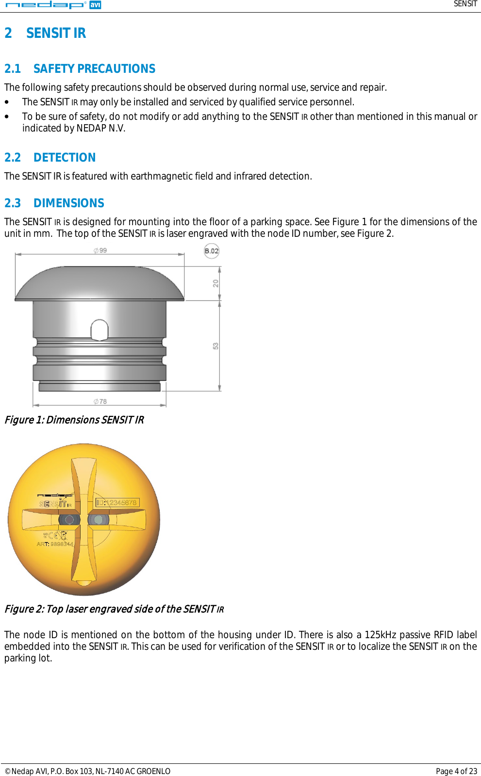
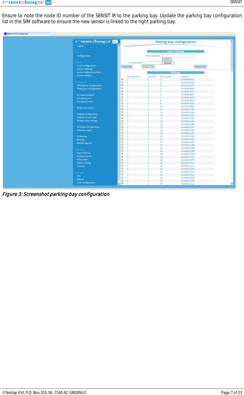
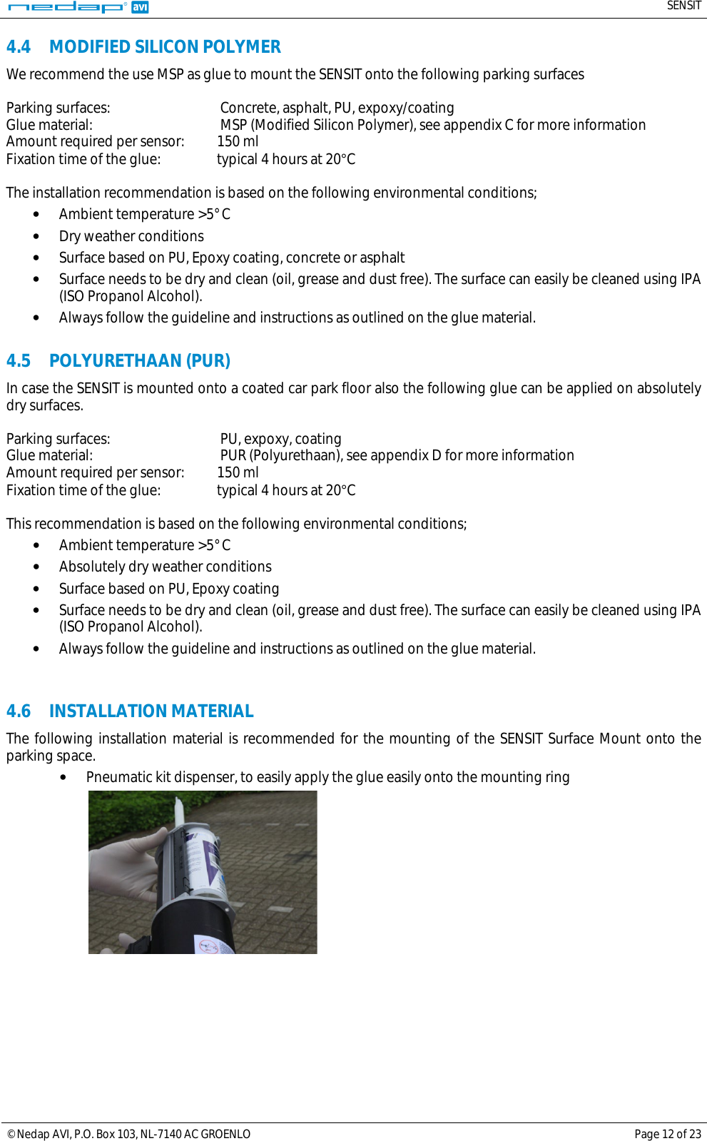
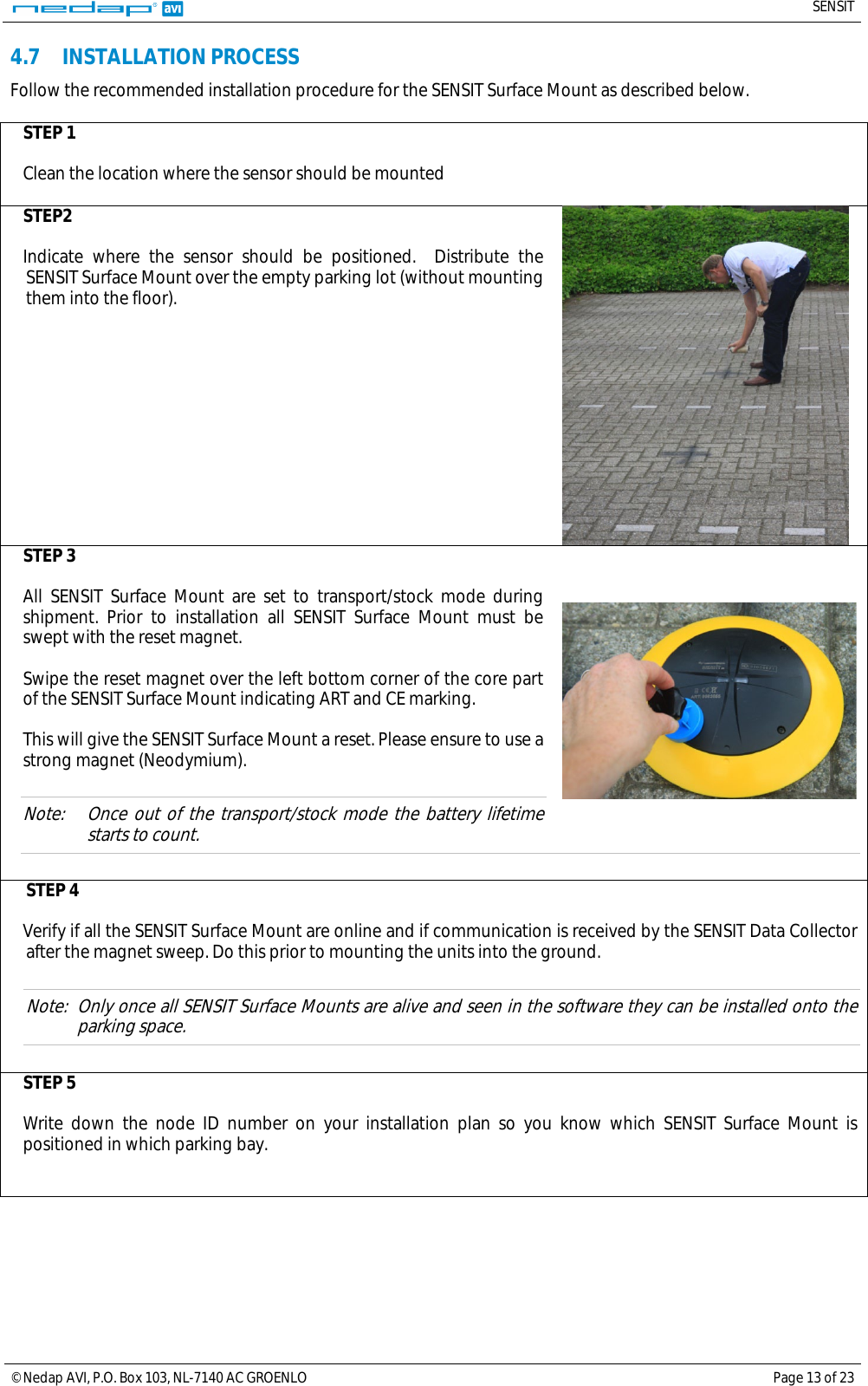
![SENSIT © Nedap AVI, P.O. Box 103, NL-7140 AC GROENLO Page 5 of 23 2.4 INSTALLATION CONDITIONS The installation recommendation is based on the following environmental conditions; - Ambient temperature between 5 to 40 °C [41 to 104 °F] - Dry weather conditions - Surface based on concrete, asphalt or pavement 2.5 REQUIRED INSTALLATION MATERIALS The following would be required for mounting of the SENSIT IR. - Equipment: Automatic drill - Drill size: Dimensions Ø 85 mm [3.35 in] - Drill depth: 54 mm [2.13 in] - Filler material: Liquid rapid mortar - Required amount per sensor: Approx 100 ml We have good results with the rapid mortar TM 5R. See appendix B for specifications. Ensure to follow the guidelines and instructions as outlined on the filler material. 2.6 INSTALLATION PROCEDURE Below the mounting procedure for the SENSIT IR. Write the ID number of the installed SENSIT on the installation plan. STEP 1 Close off the parking area STEP2 Indicate where the sensor should be positioned. Distribute the SENSIT IR over the empty parking lot (without mounting them into the floor). STEP 3 All SENSIT IR are set to transport/stock mode during shipment. Prior to installation all SENSIT IR must be swept with the reset magnet over the left bottom part of the sensor indicating the ART: XXXXXX and CE marking as indicated in Figure 2. This will give the SENSIT IR a reset. Please ensure to use a strong magnet (Neodymium). Note: Once out of the transport/stock mode the battery lifetime starts to count. STEP 4 Write down the node ID number on your installation plan so you are sure which SENSIT IR is positioned in which parking bay. STEP 5 Verify if all the SENSIT IR are online and if communication is received by the Data Collector after the magnet sweep. Do this prior to mounting the units into the ground. Note: Only once all SENSIT IR are live and seen in the software they can be installed into the pavement.](https://usermanual.wiki/Nedap-N-V/SENSITSM/User-Guide-2117170-Page-5.png)
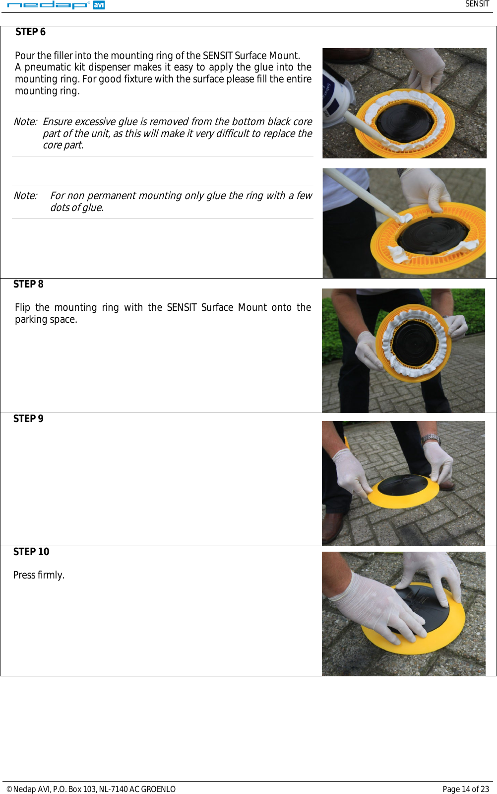
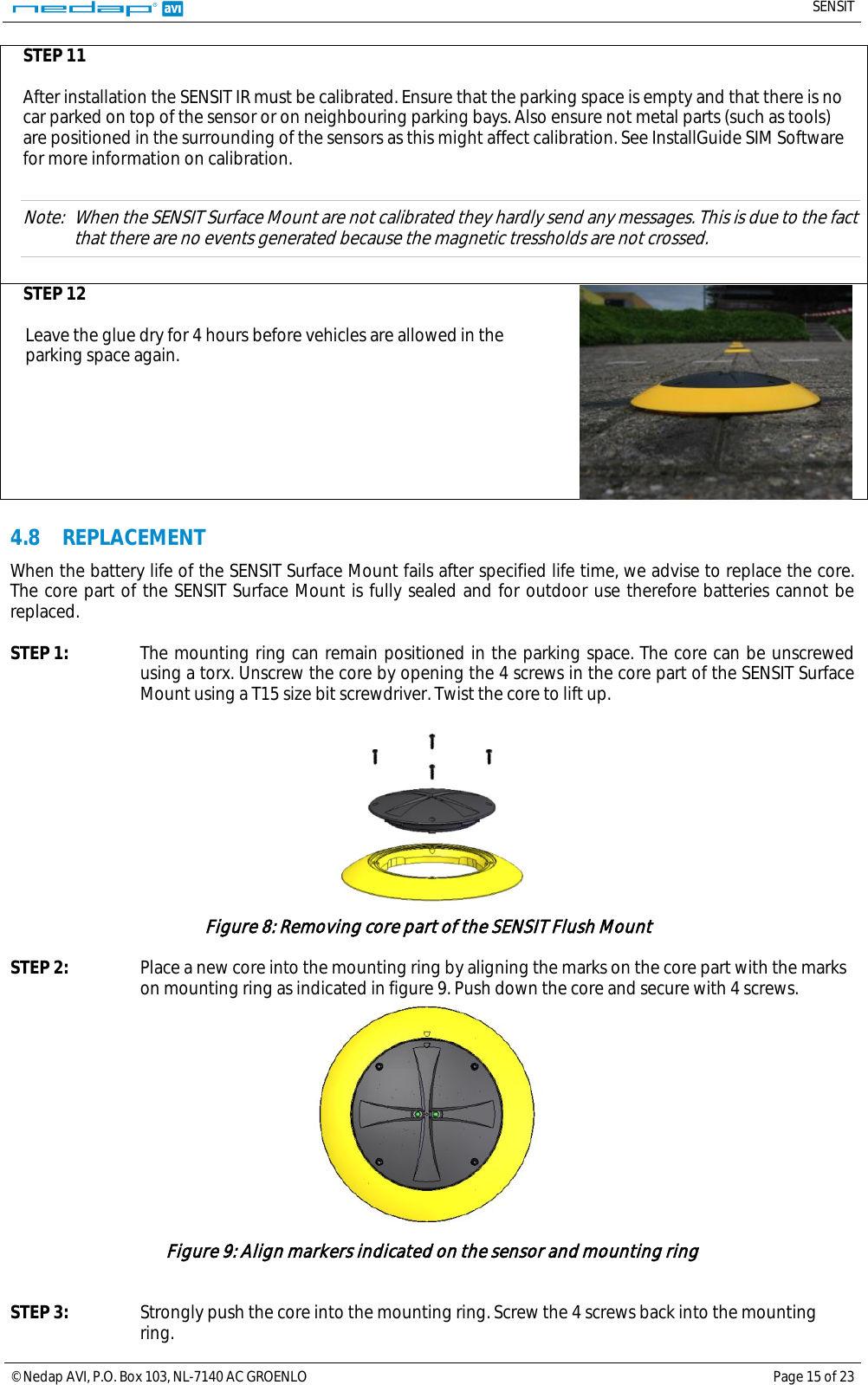
![SENSIT © Nedap AVI, P.O. Box 103, NL-7140 AC GROENLO Page 6 of 23 STEP 6 Drill a hole of 85 mm [3.35 in] into the centre of the parking bay. STEP 7 Apply the right amount of filler and pour into the hole. STEP 8 Double-check the node ID number and the parking bay on the installation plan and place the SENSIT IR into the hole. Take attention that you fixate the SENSIT during the curing time otherwise the SENSIT will start to float. STEP 9 After installation the SENSIT IR must be calibrated. Ensure that the parking space is empty and that there is no car parked on top of the sensor or on neighbouring parking bays. Also ensure not metal parts (such as tools) are positioned in the surrounding of the sensors as this might affect calibration. See InstallGuide SIM Software for more information on calibration. Note: When the SENSIT IR are not calibrated they hardly send any messages. This is due to the fact that there are no events generated because the magnetic tressholds are not crossed. STEP 10 Leave the filler harden for 8 hours before vehicles are allowed in the parking space again. 2.7 REPLACEMENT When the battery life of the SENSIT IR fails after specified life time, we advise to replace the unit completely. The SENSIT IR is fully sealed and for outdoor use therefore batteries cannot be replaced. Drill out the old SENSIT IR and complete the mounting procedure as describe in the previous paragraph.](https://usermanual.wiki/Nedap-N-V/SENSITSM/User-Guide-2117170-Page-6.png)
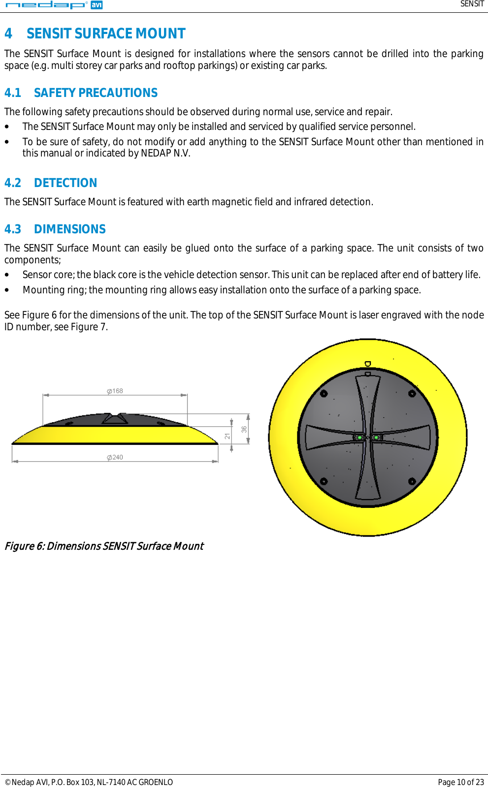
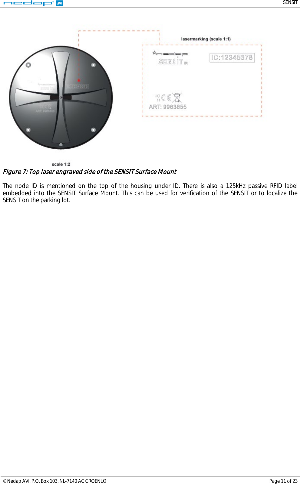
![SENSIT © Nedap AVI, P.O. Box 103, NL-7140 AC GROENLO Page 8 of 23 3 SENSIT FLUSH MOUNT 3.1 SAFETY PRECAUTIONS The following safety precautions should be observed during normal use, service and repair. • The SENSIT Surface Mount may only be installed and serviced by qualified service personnel. • To be sure of safety, do not modify or add anything to the SENSIT Surface Mount other than mentioned in this manual or indicated by NEDAP N.V. 3.2 DETECTION The SENSIT Flush mount is featured with earth magnetic field detection. 3.3 DIMENSIONS The SENSIT Flush Mount is designed for full mounting into the floor of a parking space. As the unit is fully flush with the road surface the unit is snow plough resistant. The SENSIT Flush Mount is only featured with magnetic detection. See Figure 1 for the dimensions of the unit in mm. The top of the SENSIT Flush Mount is laser engraved with the node ID number. Figure 4: Dimensions SENSIT Flush mount The node ID is mentioned on the top of the housing under ID. There is also a 125kHz passive RFID label embedded into the SENSIT Flush Mount. This can be used for verification of the SENSIT or to localize the SENSIT on the parking lot. Figure 5: Lasermarking SENSIT Flush Mount 3.4 INSTALLATION CONDITIONS The installation recommendation is based on the following environmental conditions; - Ambient temperature 5 to 40 ° C [41…104 F] - Dry weather conditions - Surface based on concrete, asphalt or pavement - Surface needs to be dry and clean (oil, grease and dust free). The surface can easily be cleaned using IPA (ISO Propanol Alcohol). 3.5 INSTALLATION MATERIAL The following would be required for mounting of the SENSIT IR. • Equipment: Automatic drill • Drill size: Dimensions Ø 85 mm [3.35 in] • Drill depth: 73 mm [3.35 in] • Filler material: Liquid concrete mortar • Required amount per sensor: Approx 100 ml](https://usermanual.wiki/Nedap-N-V/SENSITSM/User-Guide-2117170-Page-8.png)
![SENSIT © Nedap AVI, P.O. Box 103, NL-7140 AC GROENLO Page 19 of 23 7 TECHNICAL SPECIFICATIONS Technical info SENSIT IR SENSIT Surface Mount SENSIT Flush Mount Product Operating frequency 868 MHz (Europe) 902 – 928 MHz (US) 915 – 928 MHz (AUS) 868 MHz (Europe) 902 – 928 MHz (US) 915 – 928 MHz (AUS) 868 MHz (Europe) 902 – 928 MHz (US) 915 – 928 MHz (AUS) Detection Magnetic and IR Magnetic and IR Magnetic Detection accuracy 98% 98% 95% Mounting Into the floor Glued onto the floor Into the floor, flush with the surface Snowplough resistant No No Yes Load resistance Heavy traffic Regular traffic Heavy traffic Mounting dimensions Ø 78 mm [3.07 in] and 53 mm [2.09 in] high in the floor Mounting ring: Ø 240 mm [9.45 in] SensorØ 78 mm [3,07 in] and 72 mm [2.8 in] into the floor fully flush with the road surface : Ø 167 cm [6.57 in] and 35 mm [1.38 in] high Weight 365 gram [12,87 oz] 455 gram [16.05 oz] 350 gram [12.35 oz] Protection IP67, completely sealed Housing PE IP67, completely sealed Housing PE IP67, completely sealed Housing PE Colour Default black (optional yellow) Sensor black Mounting ring yellow Default black (optional yellow) Operating temperature -20 ... +85°C [-4…+185°F] -20 ... +85°C [-4…+185°F] -20 ... +85°C [-4…+185°F] Storage temperature -20 ... +85°C [-4…+185°F] -20 ... +85°C [-4…+185°F] -20 ... +85°C [-4…+185°F] Detection height 0 … 90 cm [0 … 35.5 in] 0 … 90 cm [0 … 35.5 in] 0 … 90 cm [0 … 35.5 in] Communication range Sensor to Sensor Sensor to Relay Node Sensor to Data Collector x max. 10 meters [33 ft] max. 25 meters [82 ft] max. 25 meters [82 ft] x max. 10 meters [33 ft] max. 25 meters [82 ft] max. 25 meters [82 ft] x max. 10 meters [33 ft] max. 25 meters [82 ft] max. 25 meters [82 ft] Required Relay Nodes Car parks: 1 per 50 sensors On-street parking: 1 per 25 sensors Car parks: 1 per 50 sensors On-street parking: 1 per 25 sensors 1 per 25 sensors Power supply Built in lithium battery Built in lithium battery Built in lithium battery Expected lifetime 5-10 years* 5- 9 years* 5-10 years*](https://usermanual.wiki/Nedap-N-V/SENSITSM/User-Guide-2117170-Page-19.png)