Nedap N V SENSITSM SENSIT SURFACE MOUNT User Manual SENSIT
N. V. Nederlandsche Apparatenfabriek NEDAP SENSIT SURFACE MOUNT SENSIT
14_SENSIT_InstallGuide_E CGDSENSITSM
2013-10-09
This information is furnished for guidance, and with no guarantee as to its accuracy or completeness; its publication conveys
no license under any patent or other right, nor does the publisher assume liability for any consequence of its use; specifica-
tions and availability of goods mentioned in it are subject to change without notice; it is not to be reproduced in any way, in
whole or in part, without the written consent of the publisher.
© Nedap AVI, P.O. Box 103, NL-7140 AC GROENLO Page 1 of 23
SENSIT
Installation Guide

SENSIT
© Nedap AVI, P.O. Box 103, NL-7140 AC GROENLO Page 2 of 23
CONTENTS
1 INTRODUCTION ................................................................................................................................................................ 3
1.1 SENSIT IR ................................................................................................................................................................. 3
1.2 SENSIT Flush Mount ............................................................................................................................................ 3
1.3 SENSIT Surface Mount ....................................................................................................................................... 3
2 SENSIT IR ............................................................................................................................................................................. 4
2.1 SAFETY PRECAUTIONS ....................................................................................................................................... 4
2.2 DETECTION ............................................................................................................................................................ 4
2.3 DIMENSIONS ......................................................................................................................................................... 4
2.4 INSTALLATION CONDITIONS ........................................................................................................................... 5
2.5 REQUIRED INSTALLATION MATERIALS ........................................................................................................ 5
2.6 INSTALLATION PROCEDURE ............................................................................................................................ 5
2.7 REPLACEMENT ...................................................................................................................................................... 6
3 SENSIT FLUSH MOUNT ................................................................................................................................................... 8
3.1 SAFETY PRECAUTIONS ....................................................................................................................................... 8
3.2 DETECTION ............................................................................................................................................................ 8
3.3 DIMENSIONS ......................................................................................................................................................... 8
3.4 INSTALLATION CONDITIONS ........................................................................................................................... 8
3.5 INSTALLATION MATERIAL ................................................................................................................................ 8
3.6 INSTALLATION PROCESS ................................................................................................................................... 9
3.7 REPLACEMENT ...................................................................................................................................................... 9
4 SENSIT SURFACE MOUNT ............................................................................................................................................ 10
4.1 SAFETY PRECAUTIONS ..................................................................................................................................... 10
4.2 DETECTION .......................................................................................................................................................... 10
4.3 DIMENSIONS ....................................................................................................................................................... 10
4.4 MODIFIED SILICON POLYMER ....................................................................................................................... 12
4.5 POLYURETHAAN (PUR) .................................................................................................................................... 12
4.6 INSTALLATION MATERIAL .............................................................................................................................. 12
4.7 INSTALLATION PROCESS ................................................................................................................................. 13
4.8 REPLACEMENT .................................................................................................................................................... 15
5 PROJECT SUPPORT ........................................................................................................................................................ 17
5.1 SITE SURVEY & INSTALLATION ADVICE ...................................................................................................... 17
5.2 ON-SITE CERTIFICATION .................................................................................................................................. 17
6 FCC AND IC DECLARATION ......................................................................................................................................... 18
6.1 Compliance statements (part15.19) ........................................................................................................... 18
6.2 Warning (part15.21) .......................................................................................................................................... 18
6.3 RF Exposure (OET Bulletin 65) ....................................................................................................................... 18
6.4 Information to the User (Part 15.106(b)) ................................................................................................... 18
7 TECHNICAL SPECIFICATIONS ..................................................................................................................................... 19
A PART NUMBERS .............................................................................................................................................................. 20
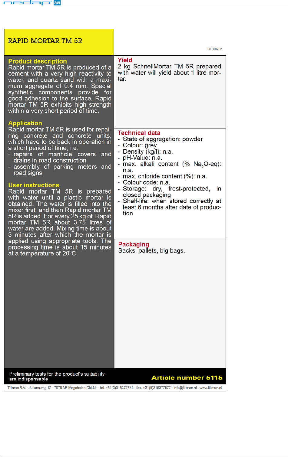
B RAPID MORTAR ............................................................................................................................................................... 21
C Modified Silicon Polymer ............................................................................................................................................ 22
D POLYURETHAN ................................................................................................................................................................ 23

SENSIT
© Nedap AVI, P.O. Box 103, NL-7140 AC GROENLO Page 3 of 23
1 INTRODUCTION
The SENSIT vehicle detection system facilitates accurate measurement on occupancy of individual parking
spaces in car parks, and on-street parking spaces. This information can be used to guide traffic to free parking
spaces but can also be used for on-street parking enforcement and overstay detection. For on-street
enforcement the number of occupied parking spaces can be compared with the number of payments realized
by the pay station. For overstay detection the system alerts instantly a parking officer to the presence of nearby
overstaying vehicles. Based on this information you can exactly determine which space to enforce.
All the SENSIT vehicle detection sensors are featured with detection and communicate wireless, creating their
own network. The SENSIT sensors do not require power wiring, in contrast to conventional systems that require
wiring throughout the car park and mounting onto the ceiling.
Easy installation of the sensors is guaranteed. Once installed no maintenance is required for years. The actual
status (occupancy) of the sensor is transmitted to the Relay Node, which is part of the wireless mesh network.
Different types of ruggedly designed sensors are available to accommodate installation in indoor car parks, on-
street spaces and road surfaces.
1.1 SENSIT IR
Vehicle detection sensor featured with dual detection technology (infrared and earthmagnetic field detection.
The SENSIT IR is mounted into the floor of each parking space allowing for vandal proof installation, making the
unit suitable for on-street application.
1.2 SENSIT Flush Mount
Vehicle detection sensor for flush mount installation with the road surface. The sensor is resistant to snow
ploughs and offers vandal proof installation. The SENSIT Flush Mount is featured with earth magnetic field
detection.
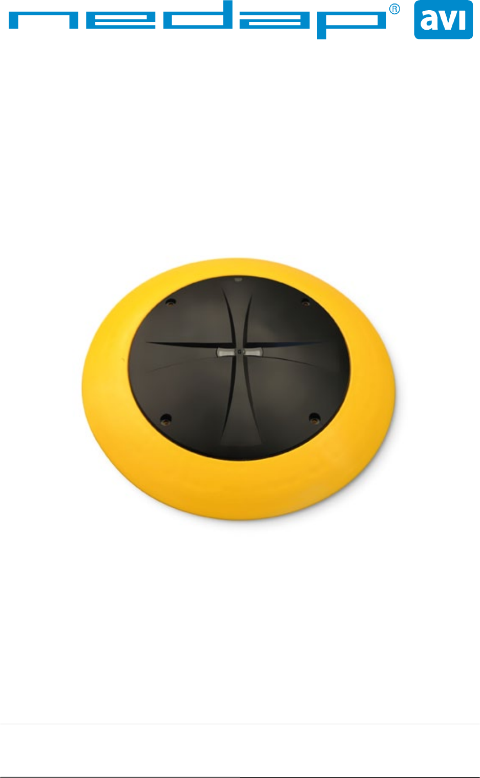
1.3 SENSIT Surface Mount
Vehicle detection sensor designed for car parks where drilling is not allowed or non permanent mounting is
required. The unit is suitable for indoor car parks and rooftop parkings. The sensor can easily be glued onto the
surface. Replacement can be achieved by removing the sensor installed in the mounting ring. The SENSIT Flush
Mount is featured with dual detection technology (infrared and earth magnetic field).
SENSIT
© Nedap AVI, P.O. Box 103, NL-7140 AC GROENLO Page 4 of 23
2 SENSIT IR
2.1 SAFETY PRECAUTIONS
The following safety precautions should be observed during normal use, service and repair.
• The SENSIT IR may only be installed and serviced by qualified service personnel.
• To be sure of safety, do not modify or add anything to the SENSIT IR other than mentioned in this manual or
indicated by NEDAP N.V.
2.2 DETECTION
The SENSIT IR is featured with earthmagnetic field and infrared detection.
2.3 DIMENSIONS
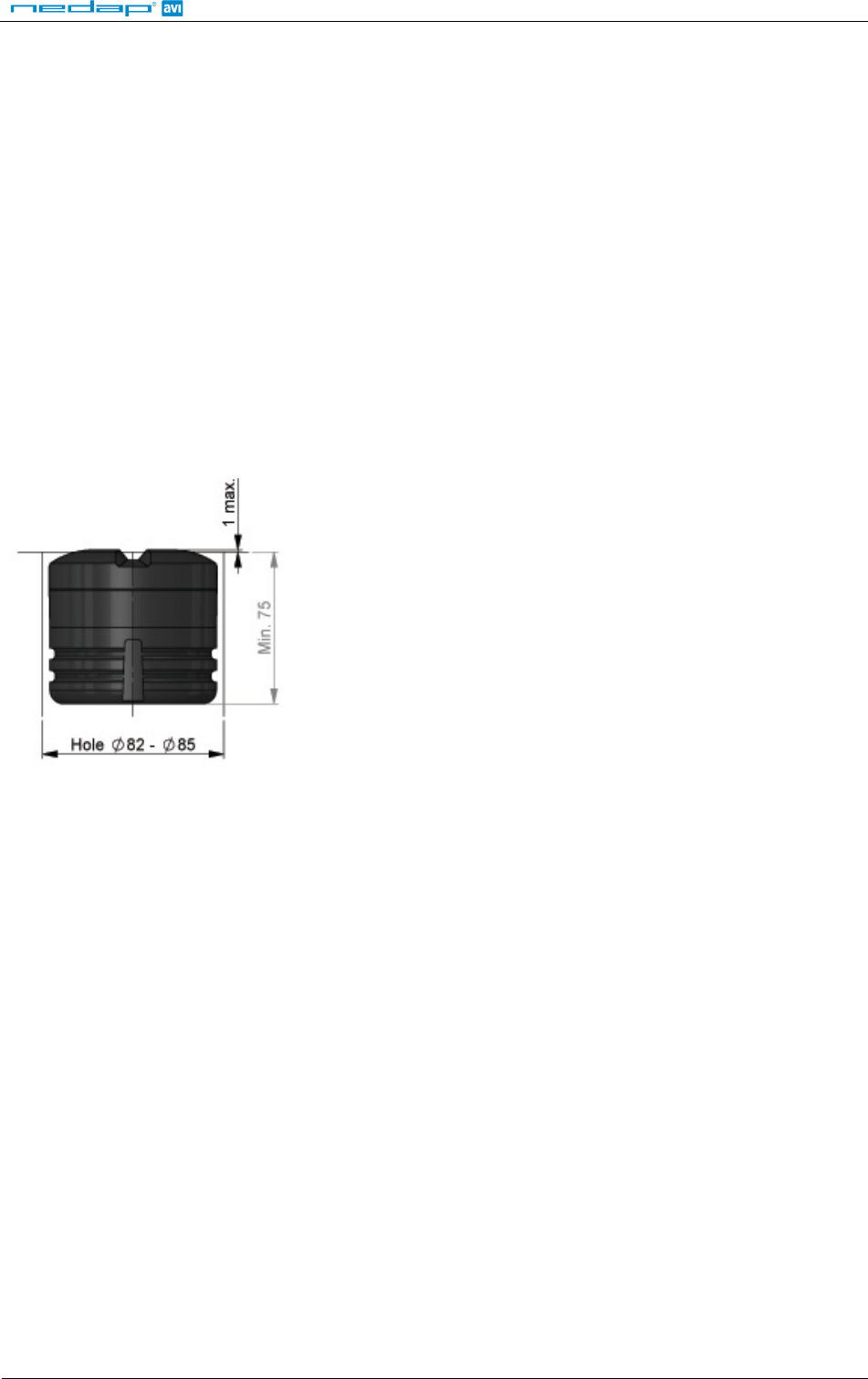
The SENSIT IR is designed for mounting into the floor of a parking space. See Figure 1 for the dimensions of the
unit in mm. The top of the SENSIT IR is laser engraved with the node ID number, see Figure 2.
Figure 1: Dimensions SENSIT IR
Figure 2: Top laser engraved side of the SENSIT IR
The node ID is mentioned on the bottom of the housing under ID. There is also a 125kHz passive RFID label
embedded into the SENSIT IR. This can be used for verification of the SENSIT IR or to localize the SENSIT IR on the
parking lot.
SENSIT
© Nedap AVI, P.O. Box 103, NL-7140 AC GROENLO Page 5 of 23
2.4 INSTALLATION CONDITIONS
The installation recommendation is based on the following environmental conditions;
- Ambient temperature between 5 to 40 °C [41 to 104 °F]
- Dry weather conditions
- Surface based on concrete, asphalt or pavement
2.5 REQUIRED INSTALLATION MATERIALS
The following would be required for mounting of the SENSIT IR.
- Equipment: Automatic drill
- Drill size: Dimensions Ø 85 mm [3.35 in]
- Drill depth: 54 mm [2.13 in]
- Filler material: Liquid rapid mortar
- Required amount per sensor: Approx 100 ml
We have good results with the rapid mortar TM 5R. See appendix B for specifications. Ensure to follow the
guidelines and instructions as outlined on the filler material.
2.6 INSTALLATION PROCEDURE
Below the mounting procedure for the SENSIT IR. Write the ID number of the installed SENSIT on the installation
plan.
STEP 1
Close off the parking area
STEP2
Indicate where the sensor should be positioned. Distribute the SENSIT IR over the
empty parking lot (without mounting them into the floor).
STEP 3
All SENSIT IR are set to transport/stock mode during shipment. Prior to installation all SENSIT IR must be swept
with the reset magnet over the left bottom part of the sensor indicating the ART: XXXXXX and CE marking as
indicated in Figure 2. This will give the SENSIT IR a reset. Please ensure to use a strong magnet (Neodymium).
Note: Once out of the transport/stock mode the battery lifetime starts to count.
STEP 4
Write down the node ID number on your installation plan so you are sure which SENSIT IR is positioned in which
parking bay.
STEP 5
Verify if all the SENSIT IR are online and if communication is received by the Data Collector after the magnet
sweep. Do this prior to mounting the units into the ground.
Note: Only once all SENSIT IR are live and seen in the software they can be installed into the pavement.
SENSIT
© Nedap AVI, P.O. Box 103, NL-7140 AC GROENLO Page 6 of 23
STEP 6
Drill a hole of 85 mm [3.35 in] into the centre of the parking bay.
STEP 7
Apply the right amount of filler and pour into the hole.
STEP 8
Double-check the node ID number and the parking bay on the installation
plan and place the SENSIT IR into the hole. Take attention that you fixate
the SENSIT during the curing time otherwise the SENSIT will start to float.
STEP 9
After installation the SENSIT IR must be calibrated. Ensure that the parking space is empty and that there is no car
parked on top of the sensor or on neighbouring parking bays. Also ensure not metal parts (such as tools) are
positioned in the surrounding of the sensors as this might affect calibration. See InstallGuide SIM Software for
more information on calibration.
Note:
When the SENSIT IR are not calibrated they hardly send any messages. This is due to the fact that there
are no events generated because the magnetic tressholds are not crossed.
STEP 10
Leave the filler harden for 8 hours before vehicles are allowed in the
parking space again.
2.7 REPLACEMENT
When the battery life of the SENSIT IR fails after specified life time, we advise to replace the unit completely. The
SENSIT IR is fully sealed and for outdoor use therefore batteries cannot be replaced.
Drill out the old SENSIT IR and complete the mounting procedure as describe in the previous paragraph.
SENSIT
© Nedap AVI, P.O. Box 103, NL-7140 AC GROENLO Page 7 of 23
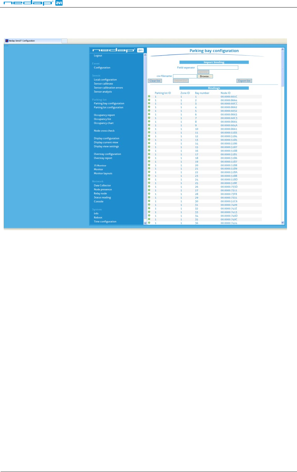
Ensure to note the node ID number of the SENSIT IR to the parking bay. Update the parking bay configuration
list in the SIM software to ensure the new sensor is linked to the right parking bay.
Figure 3: Screenshot parking bay configuration
SENSIT
© Nedap AVI, P.O. Box 103, NL-7140 AC GROENLO Page 8 of 23
3 SENSIT FLUSH MOUNT
3.1 SAFETY PRECAUTIONS
The following safety precautions should be observed during normal use, service and repair.
• The SENSIT Surface Mount may only be installed and serviced by qualified service personnel.
• To be sure of safety, do not modify or add anything to the SENSIT Surface Mount other than mentioned in
this manual or indicated by NEDAP N.V.
3.2 DETECTION
The SENSIT Flush mount is featured with earth magnetic field detection.
3.3 DIMENSIONS
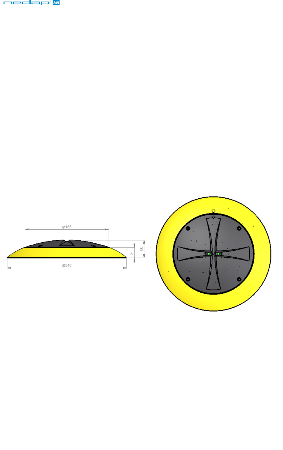
The SENSIT Flush Mount is designed for full mounting into the floor of a parking space. As the unit is fully flush
with the road surface the unit is snow plough resistant. The SENSIT Flush Mount is only featured with magnetic
detection. See Figure 1 for the dimensions of the unit in mm. The top of the SENSIT Flush Mount is laser
engraved with the node ID number.
Figure 4: Dimensions SENSIT Flush mount
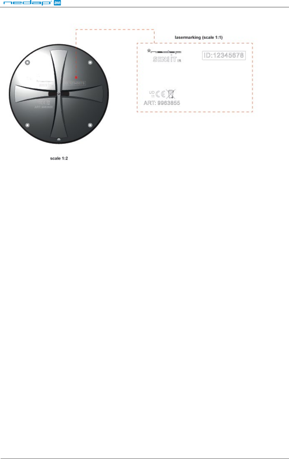
The node ID is mentioned on the top of the housing under ID. There is also a 125kHz passive RFID label
embedded into the SENSIT Flush Mount. This can be used for verification of the SENSIT or to localize the SENSIT
on the parking lot.
Figure 5: Lasermarking SENSIT Flush Mount
3.4 INSTALLATION CONDITIONS
The installation recommendation is based on the following environmental conditions;
- Ambient temperature 5 to 40 ° C [41…104 F]
- Dry weather conditions
- Surface based on concrete, asphalt or pavement
- Surface needs to be dry and clean (oil, grease and dust free). The surface can easily be cleaned using IPA
(ISO Propanol Alcohol).
3.5 INSTALLATION MATERIAL
The following would be required for mounting of the SENSIT IR.
• Equipment: Automatic drill
• Drill size: Dimensions Ø 85 mm [3.35 in]
• Drill depth: 73 mm [3.35 in]
• Filler material: Liquid concrete mortar
• Required amount per sensor: Approx 100 ml

SENSIT
© Nedap AVI, P.O. Box 103, NL-7140 AC GROENLO Page 9 of 23
We have good results with the rapid mortar TM 5R. See appendix B for specifications. Ensure to follow the
guidelines and instructions as outlined on the filler material.
3.6 INSTALLATION PROCESS
Installation process as described in paragraph 2.6, however with above mentioned drilling depth.
3.7 REPLACEMENT
When the battery life of the SENSIT Flush Mount fails after specified life time, we advise to replace the unit
completely. The SENSIT Flush Mount is fully sealed, therefore batteries cannot be replaced. Drill out the old
SENSIT Flush Mount and complete the mounting procedure as described in paragraph 2.6.
Ensure to note the node ID number of the SENSIT IR to the parking bay. Update the parking bay configuration
list in the SIM software to ensure the new sensor is linked to the right parking bay as described in paragraph 2.7.
SENSIT
© Nedap AVI, P.O. Box 103, NL-7140 AC GROENLO Page 10 of 23
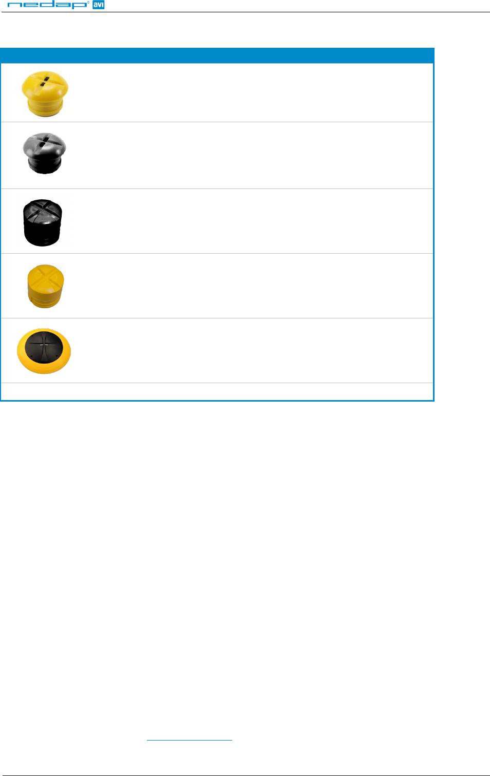
4 SENSIT SURFACE MOUNT
The SENSIT Surface Mount is designed for installations where the sensors cannot be drilled into the parking
space (e.g. multi storey car parks and rooftop parkings) or existing car parks.
4.1 SAFETY PRECAUTIONS
The following safety precautions should be observed during normal use, service and repair.
• The SENSIT Surface Mount may only be installed and serviced by qualified service personnel.
• To be sure of safety, do not modify or add anything to the SENSIT Surface Mount other than mentioned in
this manual or indicated by NEDAP N.V.
4.2 DETECTION
The SENSIT Surface Mount is featured with earth magnetic field and infrared detection.
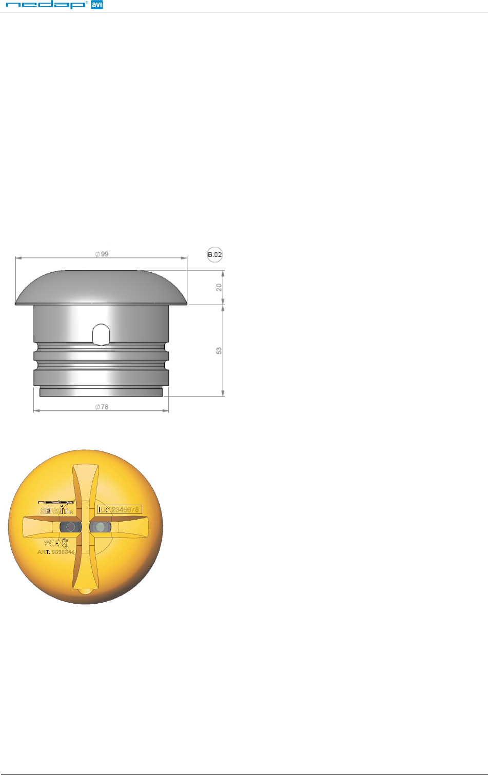
4.3 DIMENSIONS
The SENSIT Surface Mount can easily be glued onto the surface of a parking space. The unit consists of two
components;
• Sensor core; the black core is the vehicle detection sensor. This unit can be replaced after end of battery life.
• Mounting ring; the mounting ring allows easy installation onto the surface of a parking space.
See Figure 6 for the dimensions of the unit. The top of the SENSIT Surface Mount is laser engraved with the node
ID number, see Figure 7.
Figure 6: Dimensions SENSIT Surface Mount
SENSIT
© Nedap AVI, P.O. Box 103, NL-7140 AC GROENLO Page 11 of 23
Figure 7: Top laser engraved side of the SENSIT Surface Mount
The node ID is mentioned on the top of the housing under ID. There is also a 125kHz passive RFID label
embedded into the SENSIT Surface Mount. This can be used for verification of the SENSIT or to localize the
SENSIT on the parking lot.
SENSIT
© Nedap AVI, P.O. Box 103, NL-7140 AC GROENLO Page 12 of 23
4.4 MODIFIED SILICON POLYMER
We recommend the use MSP as glue to mount the SENSIT onto the following parking surfaces
Parking surfaces: Concrete, asphalt, PU, expoxy/coating
Glue material: MSP (Modified Silicon Polymer), see appendix C for more information
Amount required per sensor: 150 ml
Fixation time of the glue: typical 4 hours at 20°C
The installation recommendation is based on the following environmental conditions;
• Ambient temperature >5° C
• Dry weather conditions
• Surface based on PU, Epoxy coating, concrete or asphalt
• Surface needs to be dry and clean (oil, grease and dust free). The surface can easily be cleaned using IPA
(ISO Propanol Alcohol).
• Always follow the guideline and instructions as outlined on the glue material.
4.5 POLYURETHAAN (PUR)
In case the SENSIT is mounted onto a coated car park floor also the following glue can be applied on absolutely
dry surfaces.
Parking surfaces: PU, expoxy, coating
Glue material: PUR (Polyurethaan), see appendix D for more information
Amount required per sensor: 150 ml
Fixation time of the glue: typical 4 hours at 20°C
This recommendation is based on the following environmental conditions;
• Ambient temperature >5° C
• Absolutely dry weather conditions
• Surface based on PU, Epoxy coating
• Surface needs to be dry and clean (oil, grease and dust free). The surface can easily be cleaned using IPA
(ISO Propanol Alcohol).
• Always follow the guideline and instructions as outlined on the glue material.
4.6 INSTALLATION MATERIAL
The following installation material is recommended for the mounting of the SENSIT Surface Mount onto the
parking space.
• Pneumatic kit dispenser, to easily apply the glue easily onto the mounting ring
SENSIT
© Nedap AVI, P.O. Box 103, NL-7140 AC GROENLO Page 13 of 23
4.7 INSTALLATION PROCESS
Follow the recommended installation procedure for the SENSIT Surface Mount as described below.
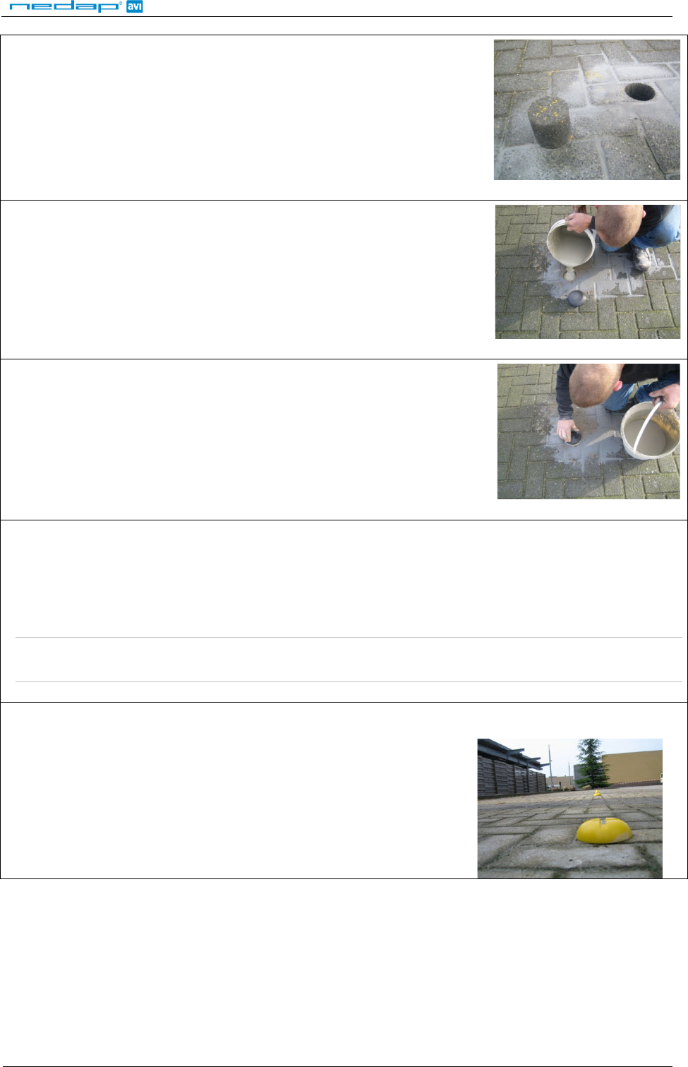
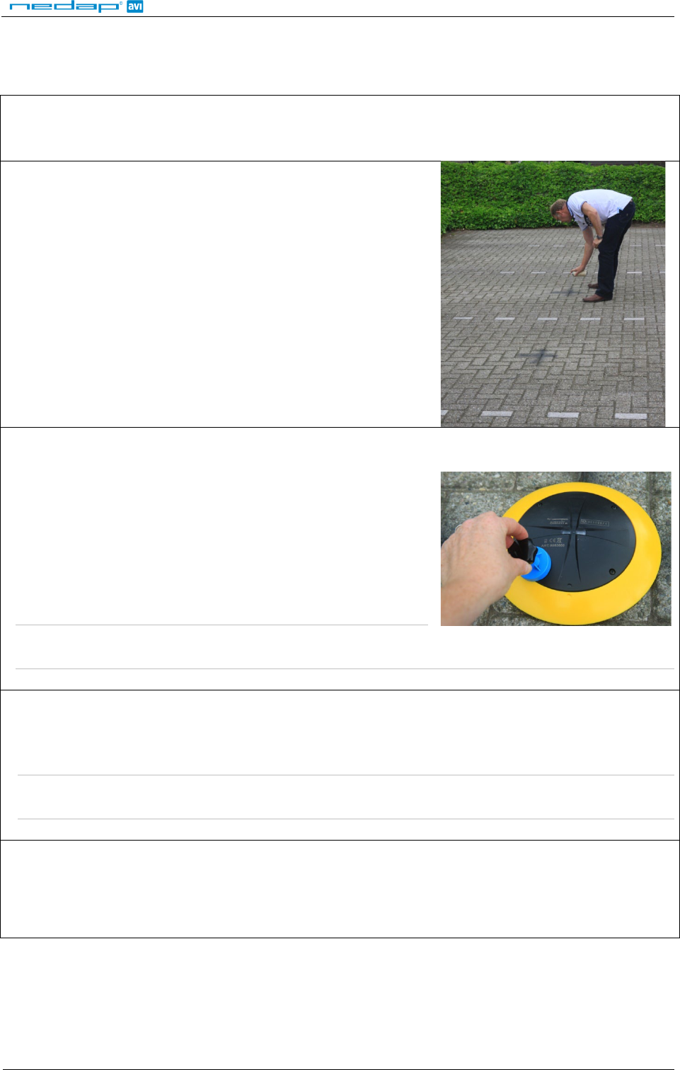
STEP 1
Clean the location where the sensor should be mounted
STEP2
Indicate where the sensor should be positioned. Distribute the
SENSIT Surface Mount over the empty parking lot (without mounting
them into the floor).
STEP 3
All SENSIT Surface Mount are set to transport/stock mode during
shipment. Prior to installation all SENSIT Surface Mount must be
swept with the reset magnet.
Swipe the reset magnet over the left bottom corner of the core part
of the SENSIT Surface Mount indicating ART and CE marking.
This will give the SENSIT Surface Mount a reset. Please ensure to use a
strong magnet (Neodymium).
Note: Once out of the transport/stock mode the battery lifetime
starts to count.
STEP 4
Verify if all the SENSIT Surface Mount are online and if communication is received by the SENSIT Data Collector
after the magnet sweep. Do this prior to mounting the units into the ground.
Note:
Only once all SENSIT Surface Mounts are alive and seen in the software they can be installed onto the
parking space.
STEP 5
Write down the node ID number on your installation plan so you know which SENSIT Surface Mount is
positioned in which parking bay.
SENSIT
© Nedap AVI, P.O. Box 103, NL-7140 AC GROENLO Page 14 of 23
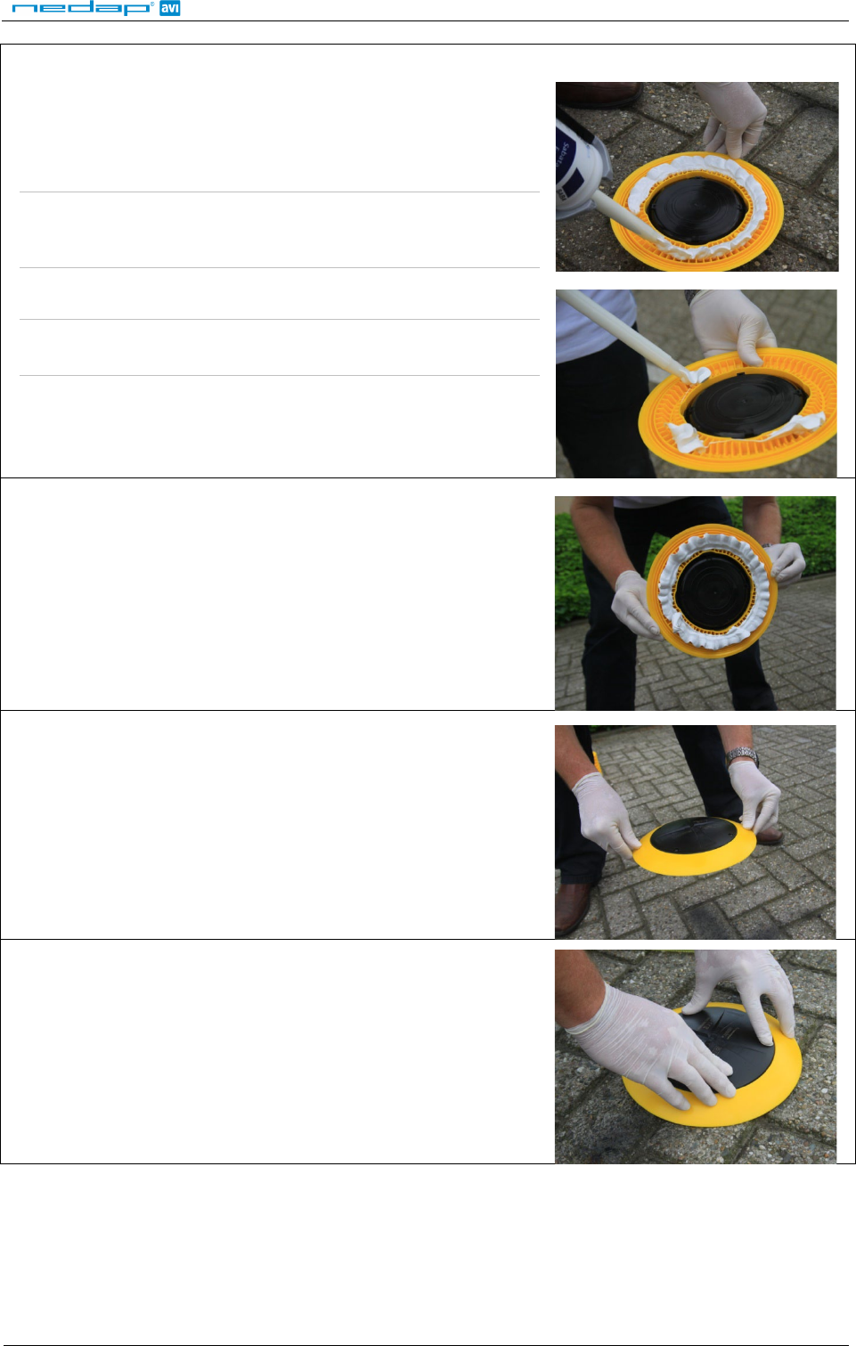
STEP 6
Pour the filler into the mounting ring of the SENSIT Surface Mount.
A pneumatic kit dispenser makes it easy to apply the glue into the
mounting ring. For good fixture with the surface please fill the entire
mounting ring.
Note: Ensure excessive glue is removed from the bottom black core
part of the unit, as this will make it very difficult to replace the
core part.
Note: For non permanent mounting only glue the ring with a few
dots of glue.
STEP 8
Flip the mounting ring with the SENSIT Surface Mount onto the
parking space.
STEP 9
STEP 10
Press firmly.
SENSIT
© Nedap AVI, P.O. Box 103, NL-7140 AC GROENLO Page 15 of 23
STEP 11
After installation the SENSIT IR must be calibrated. Ensure that the parking space is empty and that there is no
car parked on top of the sensor or on neighbouring parking bays. Also ensure not metal parts (such as tools)
are positioned in the surrounding of the sensors as this might affect calibration. See InstallGuide SIM Software
for more information on calibration.
Note:
When the SENSIT Surface Mount are not calibrated they hardly send any messages. This is due to the fact
that there are no events generated because the magnetic tressholds are not crossed.
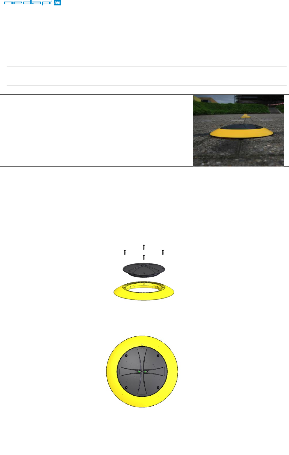
STEP 12
Leave the glue dry for 4 hours before vehicles are allowed in the
parking space again.
4.8 REPLACEMENT
When the battery life of the SENSIT Surface Mount fails after specified life time, we advise to replace the core.
The core part of the SENSIT Surface Mount is fully sealed and for outdoor use therefore batteries cannot be
replaced.
STEP 1: The mounting ring can remain positioned in the parking space. The core can be unscrewed
using a torx. Unscrew the core by opening the 4 screws in the core part of the SENSIT Surface
Mount using a T15 size bit screwdriver. Twist the core to lift up.
Figure 8: Removing core part of the SENSIT Flush Mount
STEP 2: Place a new core into the mounting ring by aligning the marks on the core part with the marks
on mounting ring as indicated in figure 9. Push down the core and secure with 4 screws.
Figure 9: Align markers indicated on the sensor and mounting ring
STEP 3: Strongly push the core into the mounting ring. Screw the 4 screws back into the mounting
ring.

SENSIT
© Nedap AVI, P.O. Box 103, NL-7140 AC GROENLO Page 16 of 23
STEP 4: After installation the SENSIT Surface Mount must be calibrated. Ensure that the parking space is
empty and that there is no car parked on top of the sensor or on neighbouring parking bays.
STEP 5: Ensure to note the node ID number of the SENSIT Surface Mount to the parking bay and
update the parking bay configuration list in the SIM software, see paragraph 2.7.

SENSIT
© Nedap AVI, P.O. Box 103, NL-7140 AC GROENLO Page 17 of 23
5 PROJECT SUPPORT
Based on our thorough project analysis including configuration and installation advice we can offer the
customer the best AVI solution.
5.1 SITE SURVEY & INSTALLATION ADVICE
This will consist of an engineer visiting the site to visually inspect and analyze the location. We will then carry out
calculations and provide you with detailed configuration and installation advice for the equipment for a specific
project.
5.2 ON-SITE CERTIFICATION
An engineer will visit the site to inspect the installation of the equipment on reliable and accurate detection.
Nedap engineers are not involved in installation (wiring) of any equipment. The installation must be completed
before the engineer arrives on-site. We will ensure that the operation confirms our commissioning requirements,
only on condition of prior given installation advice.

SENSIT
© Nedap AVI, P.O. Box 103, NL-7140 AC GROENLO Page 18 of 23
6 FCC AND IC DECLARATION
6.1 Compliance statements (part15.19)
This device complies with part 15 of the FCC Rules and to RSS210 of Industry Canada.
Operating is subject to the following two conditions:
(1) This device may not cause harmful interference, and
(2) This device must accept any interference received, including interference that may cause undesired
operation.
Cet appareil se conforme aux normes RSS 210 exemptés de license du Industry Canada.
L’opération est soumis aux deux conditions suivantes:
(1) cet appareil ne doit causer aucune interférence, et
(2) cet appareil doit accepter n’importe quelle interférence, y inclus interférence qui peut causer une
opération non pas voulu de cet appareil
6.2 Warning (part15.21)
Changes or modifications not expressly approved by party responsible for compliance could void the user’s
authority to operate the equipment.
6.3 RF Exposure (OET Bulletin 65)
To comply with FCC RF exposure requirements for mobile transmitting devices, this transmitter should only be
used or installed at locations where there is at least 20cm separation distance between the antenna and all
persons.
6.4 Information to the User (Part 15.106(b))
Note: This equipment has been tested and found to comply with the limits for a class B digital device, pursuant
to part 15 of the FCC Rules. These limits are designed to provide reasonable protection against harmful
interference in a residential installation. This equipment generates uses and can radiate radio frequent energy
and, if not installed and used in accordance with the instructions, may cause harmful interference to radio
communications.
However, there is no guarantee that interference will not occur in a particular installation. If this equipment does
not cause harmful interference to radio or television reception, which can be determine by turning the
equipment off and on, the user is encouraged to try to correct the interference by one or more of the following
measures:
- Reorient or relocate some node
- Consult the dealer or an experienced radio/TV technician for help.

SENSIT
© Nedap AVI, P.O. Box 103, NL-7140 AC GROENLO Page 19 of 23
7 TECHNICAL SPECIFICATIONS
Technical info SENSIT IR SENSIT Surface Mount SENSIT Flush Mount
Product
Operating frequency
868 MHz (Europe)
902 – 928 MHz (US)
915 – 928 MHz (AUS)
868 MHz (Europe)
902 – 928 MHz (US)
915 – 928 MHz (AUS)
868 MHz (Europe)
902 – 928 MHz (US)
915 – 928 MHz (AUS)
Detection Magnetic and IR Magnetic and IR Magnetic
Detection accuracy 98% 98% 95%
Mounting
Into the floor
Glued onto the floor
Into the floor, flush with the surface
Snowplough resistant No No Yes
Load resistance
Heavy traffic
Regular traffic
Heavy traffic
Mounting dimensions
Ø 78 mm [3.07 in] and 53 mm [2.09
in] high in the floor Mounting ring
:
Ø 240 mm [9.45 in]
Sensor
Ø 78 mm [3,07 in] and 72 mm [2.8 in]
into the floor f
ully flush with the road
surface
: Ø 167 cm [6.57 in] and 35 mm
[1.38 in] high
Weight 365 gram [12,87 oz] 455 gram [16.05 oz] 350 gram [12.35 oz]
Protection IP67, completely sealed Housing PE IP67, completely sealed Housing PE IP67, completely sealed Housing PE
Colour Default black (optional yellow) Sensor black
Mounting ring yellow
Default black (optional yellow)
Operating temperature -20 ... +85°C [-4…+185°F] -20 ... +85°C [-4…+185°F] -20 ... +85°C [-4…+185°F]
Storage temperature -20 ... +85°C [-4…+185°F] -20 ... +85°C [-4…+185°F] -20 ... +85°C [-4…+185°F]
Detection height 0 … 90 cm [0 … 35.5 in] 0 … 90 cm [0 … 35.5 in] 0 … 90 cm [0 … 35.5 in]
Communication range
Sensor to Sensor
Sensor to Relay Node
Sensor to Data Collector
x
max. 10 meters [33 ft]
max. 25 meters [82 ft]
max. 25 meters [82 ft]
x
max. 10 meters [33 ft]
max. 25 meters [82 ft]
max. 25 meters [82 ft]
x
max. 10 meters [33 ft]
max. 25 meters [82 ft]
max. 25 meters [82 ft]
Required Relay Nodes Car parks: 1 per 50 sensors
On-street parking: 1 per 25 sensors
Car parks: 1 per 50 sensors
On-street parking: 1 per 25 sensors
1 per 25 sensors
Power supply Built in lithium battery Built in lithium battery Built in lithium battery
Expected lifetime 5-10 years* 5- 9 years* 5-10 years*
SENSIT
© Nedap AVI, P.O. Box 103, NL-7140 AC GROENLO Page 20 of 23
A PART NUMBERS
SENSIT Vehicle Detection sensors
SENSIT IR EU yellow
SENSIT IR US yellow
SENSIT IR AU yellow
part number: 9898344
part number: 9955909
part number: 9965947
SENSIT IR EU black
SENSIT IR US black
SENSIT IR AU black
part number: 9943374
part number: 9898620
part number: 9965955
SENSIT Flush Mount EU black
SENSIT Flush Mount US black
SENSIT Flush Mount AU black
part number: 9966960
part number: 9966978
part number: 9966986
SENSIT Flush Mount EU yellow
SENSIT Flush Mount US yellow
SENSIT Flush Mount AU yellow
part number: 9966510
part number: 9966528
part number: 9966536
SENSIT Surface Mount EU
SENSIT Surface Mount US
SENSIT Surface Mount AU
part number: 9958525
part number: 9958533
part number: 9963871
SENSIT ACTIVATION MAGNET part number: 3062198
For full product information visit www.nedapavi.com
SENSIT
© Nedap AVI, P.O. Box 103, NL-7140 AC GROENLO Page 21 of 23
B RAPID MORTAR

SENSIT
© Nedap AVI, P.O. Box 103, NL-7140 AC GROENLO Page 22 of 23
C Modified Silicon Polymer
Sabatack Fast
u l t r a - f a s t b o n d i n g
Description
Sabatack Fast is an ultra fast-acting 2-component, elastic, humidity-curing, MS polymer-based construction adhesive.
Its primary use is bonding with fast hardening, handling after only 2 hours, which makes this product excellent for use
in mass production.Sabatack Fast has a medium viscosity and a high modulus elasticity.
Field of application
Industrial and hand-made vehicle and coachwork construction, marine, ventilation and air conditions, electro-
technology, equipment assembly, metal and tin processing, plastics technology, civil & environmental engineering
and building & construction. For the elastic bonding of frames, profiles, plates etc. Also for sealing seams, overlaps,
joints and cracks. Suitable for interior and exterior use. Excellent for use in mass production.
Advantages
•fast and controlled curing, high end strength
•adhesion without primer, fast drying
•can be painted wet-on-wet, hardly any shrinkage
•no blistering, almost odourless
•free from solvents, isocyanates and silicones
•UV-stable, high temperature resistance
•certificates: Wheelmark (164.106/1121/WCL MED0326), ISEGA (in connection with HACCP)
Method of use
For instructions for use, repaintability and pre-treatment, see the relevant info sheets at www.saba.nl
TECHNICAL DATA
Order information
Other packaging and colours on request. The shelf life may vary for large packaging.
Safety recommendations
For more information about safety, see the relevant SABA safety data sheet.
Component A Component B
Basis MS polymer, humidity-curing MS polymer, humidity-curing
Density (EN 542) approx. 1.380 kg/m3 approx. 1.144 kg/m3
Solids content approx. 100% approx. 85%
Open time (23 °C, 50% RLV) approx. 10 minutes
Tack free (23 °C, 50% RLV) completely after approx. 12 hours
Cure rate (23 °C, 50% RLV) even after 48 hours
Hardness Shore A (EN ISO 868) approx. 55
Volume alteration (EN ISO 10563) < 5%
Modulus at 100% (ISO 37/DIN 53504) approx. 1.5 N/mm2
Tensile strength (ISO 37/DIN 53504) approx. 2.6 N/mm2
Elongation at break (ISO 37/DIN 53504) approx. 330%
Shear strength (ISO 4587) approx. 1.7 N/mm2
Working temperature min. +5 °C to max. +35 °C
Storage temperature min. +5 °C to max. +25 °C
Temperature resistance min. -40 °C to max. +120 °C
Short temperature resistance max. +180 °C (30 minutes)
Packaging dual-cartridge
Contents 490 ml (contains 7 items)
Colour white (similar to RAL 9003) black (similar to RAL 9011)
Article No. 100201 DJW 100862 DJW
Shelf life 9 months (in unopened packaging)

SENSIT
© Nedap AVI, P.O. Box 103, NL-7140 AC GROENLO Page 23 of 23
D POLYURETHAN
P E R M A P U R® 2 6 5 4 A / B
Universal Polyurethane liquid adhesive
PERMAPUR® 2654 A/B consists of two components A-component (Polyol) and a B-component (Isocyanate). The
resin is supplied in a bi-pack. PERMAPUR 2654 A/B is used as an universal polyurethane resin which can be
applied by pouring the fluid. The system is insensitive to moist and shows no blistering and is therefore less
critical in processing.
Technical details
Color: A-component black fluid
B component dark brown fluid
Color mix: Black
Processing time: 10 min / 20°C
Gel time: 15 min / 20°C
Curing time: 24 h /20°C
Viscosity: 4.500 mPa.sec/20°C
Hardness: 45° Shore D
Specific gravity: 1,5 g/cm3
Specific resistance: 1 x 10¹⁴ W.cm
Breakdown voltage: 20 KV/mm
Max. temperature: -25°C tot +120°C
Water absorption: <1%
Storage: At room temperature (20 ° C) in tightly closed Verpa Branching 12 months