Nedap N V SF4 134 kHz Inductive Tag Reader User Manual D300 SF4 02 gb
N. V. Nederlandsche Apparatenfabriek NEDAP 134 kHz Inductive Tag Reader D300 SF4 02 gb
UserManual.wiki
>
Nedap N V
>
SF4 User Manual
User Manual
Navigation menu
Upload a User Manual
Namespaces
Wiki Guide
HTML
PDF
Info
Views
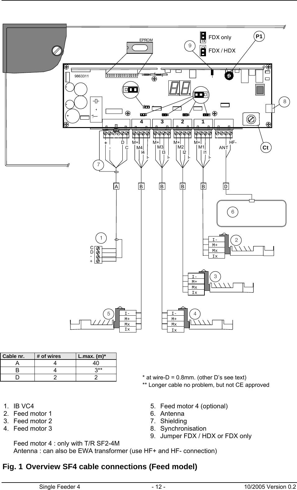
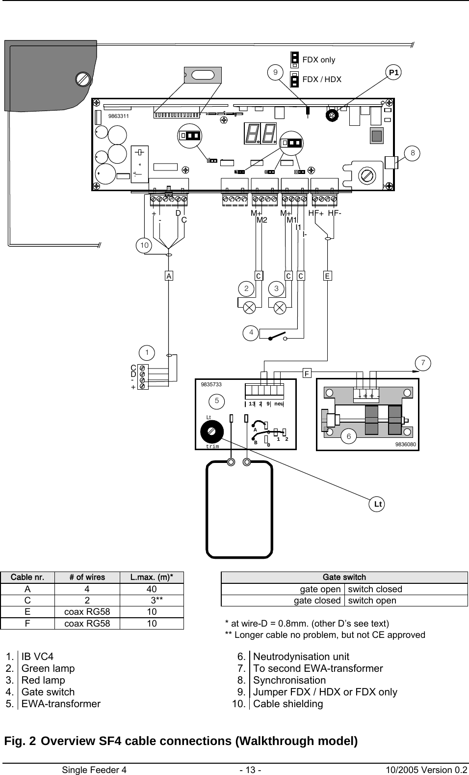
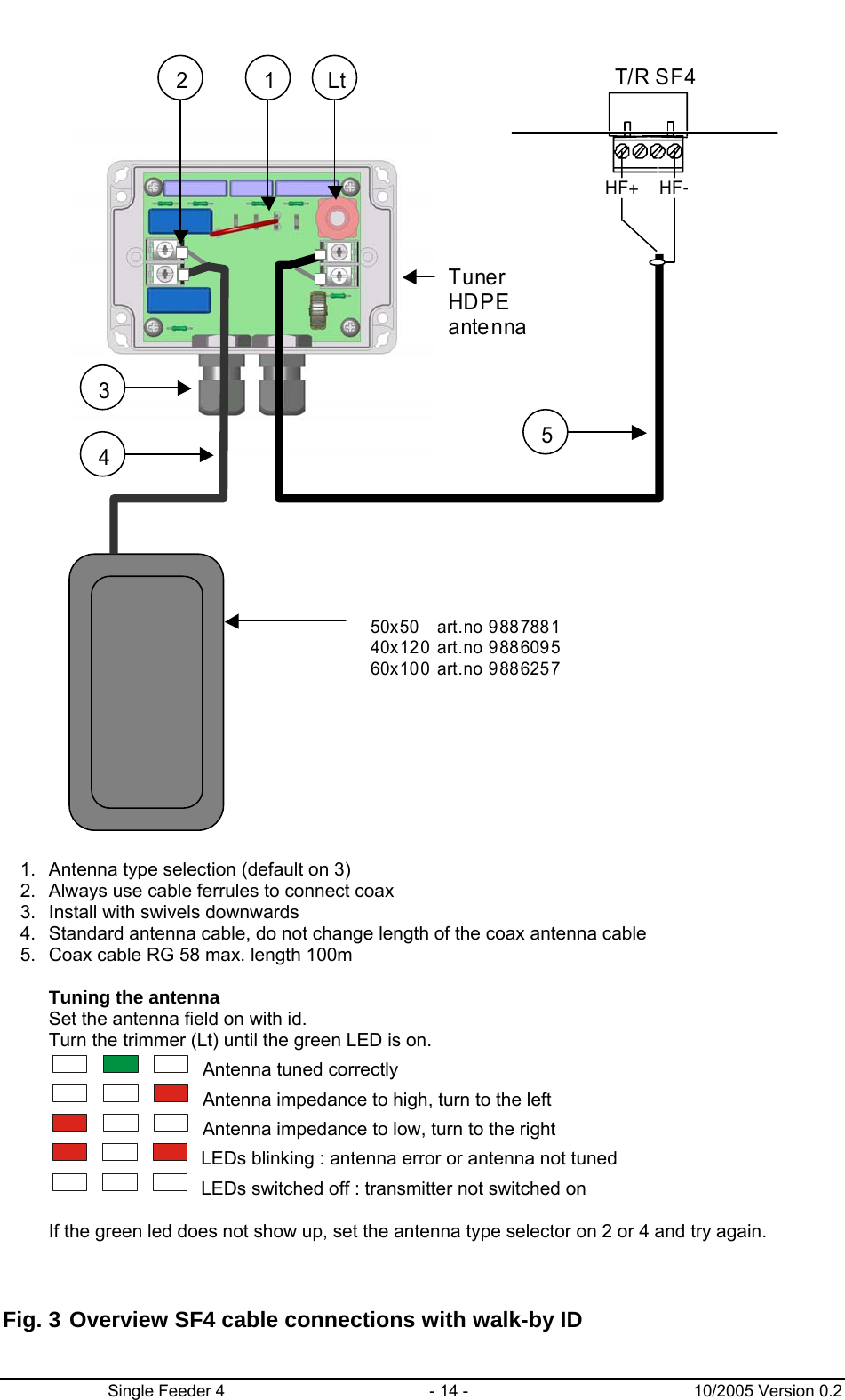
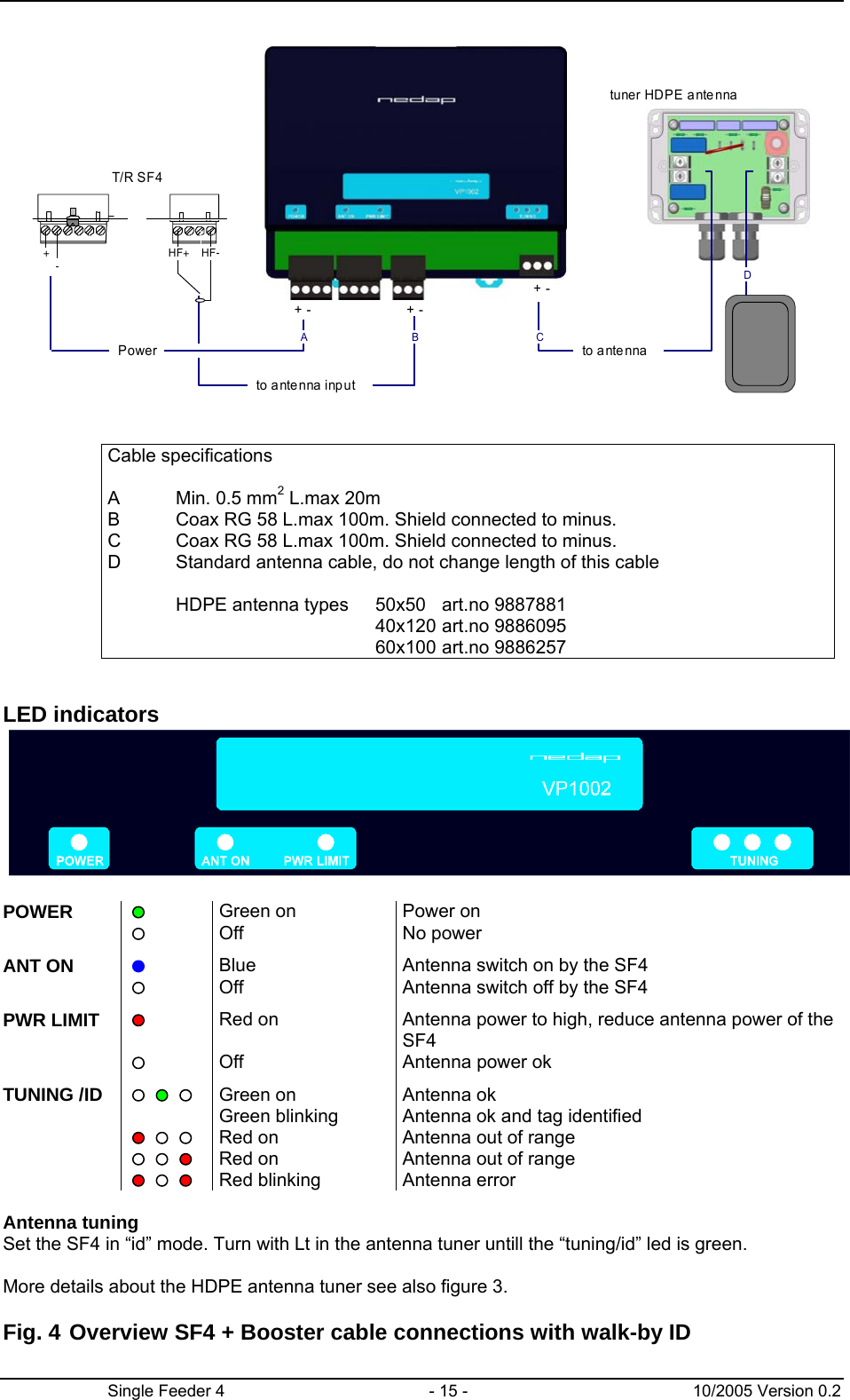
User Manual
Discussion / Help
Navigation