Nedap N V SF4 134 kHz Inductive Tag Reader User Manual D300 SF4 02 gb
N. V. Nederlandsche Apparatenfabriek NEDAP 134 kHz Inductive Tag Reader D300 SF4 02 gb
User Manual
VC4 T/R SF4 ISO FDX/HDX
CONTENTS page
1 General 1
2 Operation 1
3 Installation 2
4 Set Address 4
5 Adjust antenna 5
6 Adjust Neutrodynisation 7
6 Display values 9
7 Internal test menu 10
8 Trouble shooting 11
Fig. 1 Overview SF4 cable connections (Feed model) 12
Fig. 2 Overview SF4 cable connections (Walkthrough model) 13
Fig. 3 Overview SF4 cable connections with walk-by ID 14
Fig. 4 Overview SF4 + Booster cable connections with walk-by ID 15
Fig. 5 Display menu 16
10-2005 Nedap Agri bv
SF4.eng version 0.2

Single Feeder 4 - 1 - 10/2005 Version 0.2
1 General
The Transmitter/Receiver Single Feeder 4 (SF4) is a re-design of the SF2 and can
be used for identifying of ISO FDX en HDX responders.
SF4 compared to SF2
The SF4 print is based on the SF2. Cable connections are the same as with a SF2.
When using HDX and ISO operation a synchronisation cable must be installed.
Most important change is that FDX and HDX responder types can be identified
according to the full ISO standard 11784 and 11785.
EPROM on the T/R SF4
Eproms that are suitable for a SF2 can be used on a SF4. Important is that ISO
identification in the software is included. If ISO is possible, the ri menu option is
available at responder select.
Caution because of pulsating transmitter (HDX)
Although everything is done to minimize, there is a possibility that the magnetic
radiation of the antenna, connected to this reader, influences the behavior of a
pacemaker.
Users of a pacemaker are advised to avoid close contact between their pacemaker
and the antenna of the SF4
In Germany and Denmark the maximum allowed level is 42 dBμA /m. at 134.2 kHz.
For most other countries in Europe this maximum level is 65 dBμA/m.
2 Operation
See manual as used for a SF2

Single Feeder 4 - 2 - 10/2005 Version 0.2
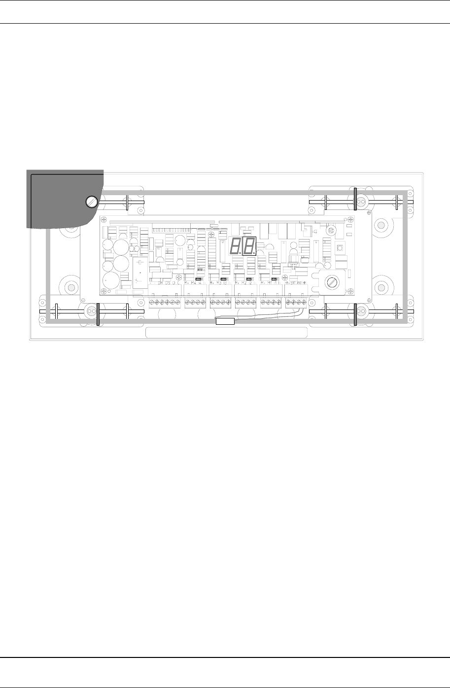
3 Installation
The Nedap guarantee-regulations are only valid when the SF4 is installed as
indicated in this manual. The following is important :
Technical specifications Single Feeder 4
Input voltage 22-42 VDC
Max. current per output (motors) 3A DC
Operating temperatures (environment) -10ºC / +45ºC
Transport / storage temperatures -25ºC / +70ºC
Humidity (rh) 45ºC / 93%
Enclosure protection class
(cover and cables installed correctly !)
IP65
Always use a NEDAP SMPS power supply
Never change a prom when the power to the T/R is still switched on
Install data cables at a safe distance from (high) powered cables
Wiring the SF4
Figure 1 shows an overview of the T/R SF4 cable-connection.
Cable specifications
Cable length at power supply 27V:
IB Æ SF4 Max. 40m at wire-ø = 0.8 mm
SF4 Æ motor Standard cable of the motor
SF4 Æ antenna Standard cable of the antenna
Synchronisation (HDX and ISO operation) Twisted pair minimum 2x0.24mm2
shielded. Total max. 500m
IMPORTANT: All cables used for data communication must have shielding!
Hardware motor safeguard
When the micro processor has no control over the T/R anymore and a motor is
running uncontrolled and keeps turning continuously, a hardware circuit on the T/R
will stop the motor by means of a relay (25 seconds (+/- 5 sec)). This motor
safeguard can only be reset by switching off the power from the T/R for a few
seconds.
Software motor safeguard
This software function monitors the motor current. If a motor current is detected
which is too high (Imotor > 900 mA) for a certain time, the T/R program will try to stop
the motor. If the motor can not be stopped, the T/R program will shut off the power
supply on all outputs.
Single Feeder 4 - 3 - 10/2005 Version 0.2
Synchronisation for HDX
A synchronisation cable is necessary for HDX to synchronise T/Rs that can influence
each other. For FDX only (jumper set to FDX only) synchronisation is not necessary.
The connector at the right hand side (SYNC) contains a synchronisation signal for
HDX (SYNC). SYNC has to be connected to all other HDX Single Feeders in the
neighbourhood. There is no + or -. Maximum number is 16 that can be connected
together for synchronization. If a cable is used with shielding, the shielding must not
be connected at the bottom plate of the PCB but left as not connected.
Jumper for FDX / HDX or FDX only
If set to FDX / HDX the red led is blinking during transmitting the synchronisation
signal.
When set to FDX only, the red led remains off.
LEDs
The tree leds are used for tuning the antenna.
The two leds are for idenfication (green) and synchronisation (red).
Shielding, grounding
In order to protect the SF4 for over-voltages / induction, the cable from the interface
bridge to the SF4 must be a shielded cable. Connections:
interface bridge connected to "-"terminal
Transmitter / Receiver connected to ground-terminal
N.B. All T/R electronics must be isolated. Also the T/R bottom plate has to be
isolated from the T/R ground-terminal.
Warnings
• Due to guarantee-regulations, the entire T/R PCB (incl. metal plate) must be
changed.
SYNC SYNC SYNC
Single Feeder 4 - 4 - 10/2005 Version 0.2
4 Set Address
For communication the Transmitter / Receiver needs an address. Then the computer
knows where to send the information to. At the transmitter / receiver with help of the
display and the push button the stations address is configured.
The two segment display and the yellow push-button must also be used for several
adjustments of the Transmitter / receiver. A number of different codes will appear on
the display when the push-button is pushed, these codes represent the so-called
menus. Each menu on its turn is divided into a number of functions. By varying the
pushing time of the push-button, you will get access to the different menus and/or
functions.
The first time you switch on the power of the T/R, the display will show "0-". The
Transmitter / Receiver asks now for the first address. When an address is entered
the display will blank out and the transmitter / receiver returns to the normal status.
The address setting concerns the following menus and procedures (see figure 3):
• Address menu
- Set Address
- display Address
N.B. Remember that the used peripheral-address has to be unique on a channel.
Changing addresses
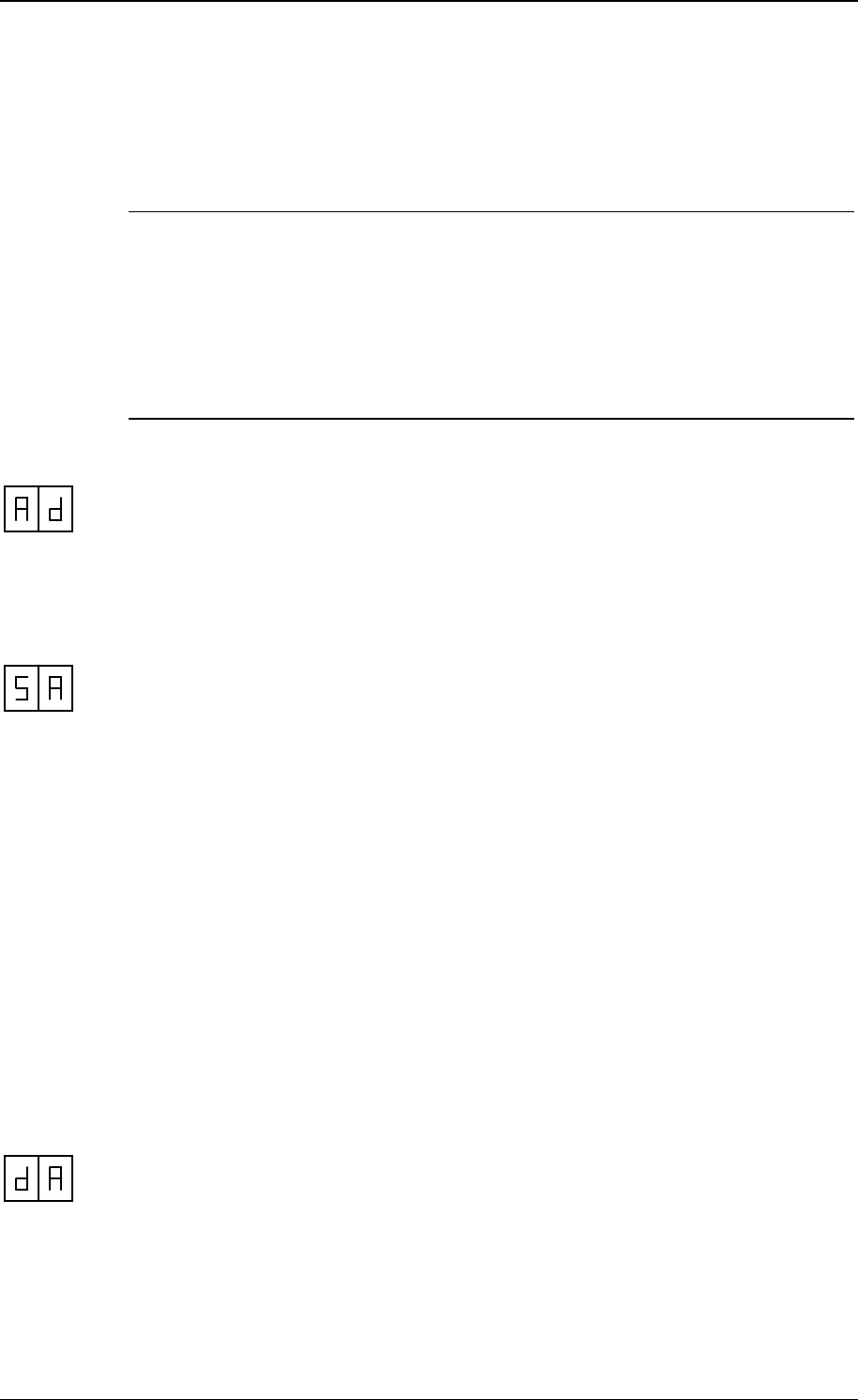
When the display shows SA, the "Set Address procedure" is entered by pressing the
button until the display blinks. The procedure is as follows :
set decimal-digit display scrolls from 0- through 1-
set unit-digit display scrolls from x0 through x9
• to indicate that the "Set Address procedure" has been entered, the display will
show "0-"
• by pressing the button short, the next decimal will be displayed ("1-")
• the displayed decimal is entered by pressing the button until the display blinks
• when the decimal has been entered, the display will show "x0" (where x = entered
decimal), the unit-digit now can be entered
• by pressing the button short, the next unit will be displayed ("x1", "x2", .. , "x9")
• the displayed unit is entered by pressing the button until the display blinks
The following points should be noted
• the "Set Address procedure" can be quit by pressing the button until the
display blanks. The entered digits then are not stored
• the T/R will restart when the address is changed
Show addresses
When the display shows dA, the "display Address procedure" is entered by pressing
the button until the display blinks. The display then shows the T/R address.
Single Feeder 4 - 5 - 10/2005 Version 0.2
5 Adjust antenna
The antenna adjustment has to be done with help of the display, push button,
potentio meter (P1) and a coil (L404) on print (or EWA transformer when using
external antenna).
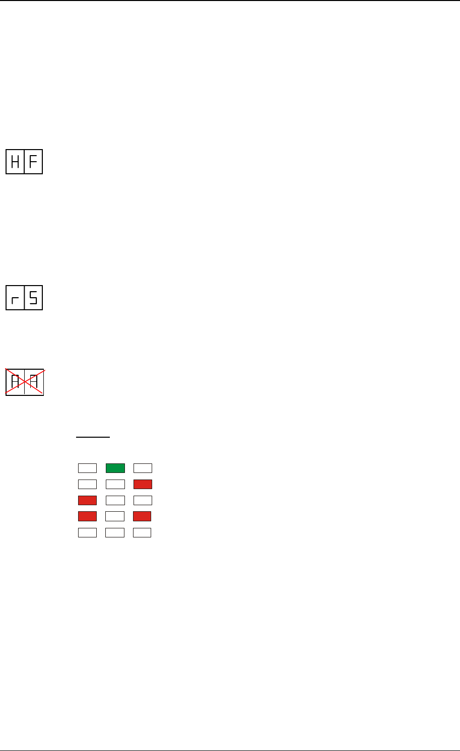
Most eproms have following HF-menu :
HF menu
Responder Select
Adjust Antenna
Adjust Power
Adjust Squelch
Identification
• selection of responder type
• not used
• adjust transmitter-power by means of potentio meter P1
• adjust receiver-sensitivity (0,1,2,3)
• test identification
⇒
The antenna adjustment-procedure consists of several steps. It is essential that
these steps are executed in the sequence as in the manual described.
Responder Select
rA = not used
rP = not used
ri = 134.2 kHz ISO responders
Select rS on the display and then ri, press until display blinks to enter.
Adjust antenna procedure
The AA-menu option is not used for the SF4. Tuning of the antenna is done with a
trimmer on the print (Ct) when using an internal antenna. When using an external
antenna the coil on the transformer (Lt) must be used. Three LEDs next to P1 are
used as indication for the tuning.
Tuning:
Set the antenna field on with id.
Turn the trimmer (Ct) until the green LED is on.
Antenna correct adjusted
Antenna impedance to high, turn to the left
Antenna impedance to low, turn to the right
LEDs blinking : antenna error or antenna not tuned
LEDs switched off : transmitter not switched on
The next step is tuning the power with AP.

Single Feeder 4 - 6 - 10/2005 Version 0.2
Power adjustment
After correct processing the antenna adjustment procedure, P1 (fig1) must be
adjusted with help of AP.
Power adjustment is used to set the ID distance. By reducing the power the reading
distance will be smaller. Power adjustment is done with a potentiometer (P1).
Changing the power level:
Select with the push button the AP-menu (adjust power) and press untill the display
starts to blink. A value appears on the display now. Turn P1 till the desired reading
distance of the ID label. Maximum power is 99.
After changing the power level always check if the green antenna tuning LED is still
on.
Adjust squelch
The adjusted squelch determines the sensitivity of the receiver in the T/R. In case
e.g. animals outside the antenna are identified, the transmitted power can be
reduced ("Adjust Power procedure") or the receiver-sensitivity can be reduced by
means of the squelch-adjustment.
Normally squelch does not have to be adjusted (automatically set to default)
When the display shows AS, the "Adjust Squelch procedure" is entered by pressing
the button until the display blinks. The display now shows the actual sensitivity of the
receiver, a value from "-0" (most sensitive) "-1", "-2" or "-3" (less sensitive).
By shortly pressing the button, the desired squelch can be adjusted. The setting can
be entered by pressing the button until the display blinks.
Test identification
The HF-field is now continuously active, switching between HDX or FDX responders,
when both types are present at the antenna.
ID-status:
- - = no responder identified
xx = responder identified ( xx = last two digits of responder number)
Single Feeder 4 - 7 - 10/2005 Version 0.2
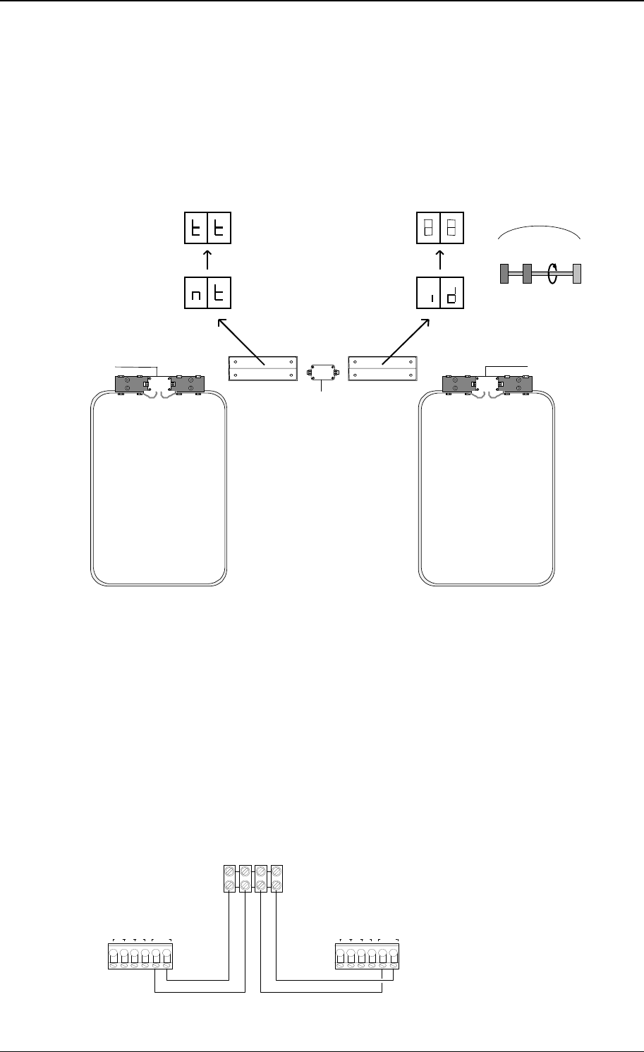
6 Adjust Neutrodynisation
Why using a neutrodynisation unit
When two large antennas are used in a small area, a responder identified in one
antenna, is also identified in the other antenna (cross talk).
Installing a neutrodynisation unit can solve this problem
9835733
9836080
9835733
0
0
00
max
1 2
Figure : Single Feeder model 4 with neutrodynisation
Principle of neutrodynisation
The neutrodynisation-unit is a small version of the big antennas. The two coils in the
box are connected to the antenna’s. By moving the coils the “cross talk problem”
between both antennas can be solved.
Tuning principle: one of the T/R is set to transmitting (tt). The other one is set to
identification (id). The transmitter will give a very strong signal. The receiver will
translate the received signal strength into a display value. A value around 10 means
cross talk.
Wiring Neutro - EWA transformer
++ --
13 2 9 neutro
+- 13 2 9 neutro
+-
NEUTRO
EWAEWA
Single Feeder 4 - 8 - 10/2005 Version 0.2
Adjustment of the neutrodynisation unit
Single Feeder model 4
IMPORTANT : Always use a synchronisation cable between both T/R.
1. Switch on the power to the system
2. Position both neutrodynisation-coils close to each other, but not touching
3. Antenna 1 :
Select “An” on the display, then “nt”, press until display blinks. The display now
shows “tt” (transmitting)
Antenna 2 :
Select “id” on the display, press until display blinks. The display now shows a
numeric value (receiving)
4. Using the SF display :
Start turning the neutro wheels from each other. The value on the display of
antenna 2 will increase. Keep on turning until the highest value appears (see
graph).
5. The neutrodynisation is now finished. It is important to do a final check.
Select the “id” menu. Set both antennas in “id” position.
Move a responder in the middle of antenna 1 (about 40-50 cm from the floor).
When the display of T/R 2 does not show the responder number, the adjustment
is OK.
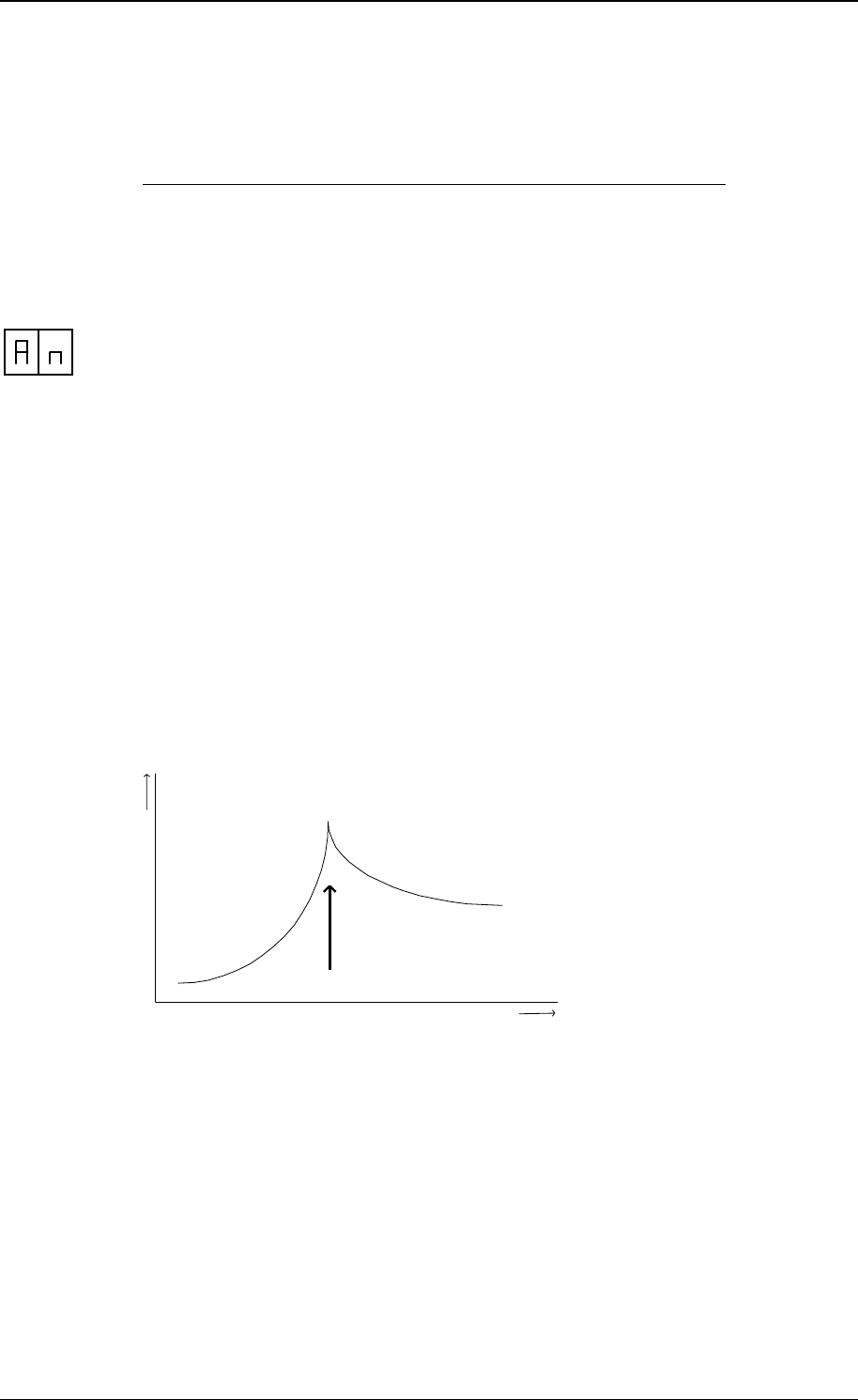
SF 4 Display neutrodynisation values explained in a graph
Display value
Optimum
distance between the neutrodynisation wheels
Trouble shooting when tuning the neutrodynisation unit
• The display does not reach a peak value when tuning
Wiring twisted (when a plus and minus in the antenna system is changed there
will be no peak in tuning the neutro)
• The display starts already with a high value and does almost not increase
There is almost no cross talk, the receiver can not or almost not detect a signal
coming from the transmitter
Single Feeder 4 - 9 - 10/2005 Version 0.2
6 Display values
During operation, the program steps through different program-states which are
monitored on the display. This gives information about the state of the T/R and
therefore can be used as an extra service tool.
The indication on the display is as follows :
Start process
status description of the status
00 start : processor-initialisation
01 wait for valid address, "SA"-menu is started automatically
02 No communication with a process computer
03 No communication with a process computer
04 T/R SF under test
05 start-up process finished
Display values during operation
See manual as used for a SF2
Single Feeder 4 - 10 - 10/2005 Version 0.2
7 Internal test menu
The Internal test menu is a powerful service tool in case of system-service. The T/R
stores registered errors which can be displayed on demand of the trouble-shooter.
Also the T/R can execute a complete self test on demand, the test results also are
displayed.
Internal test menu
− display Error procedure
− Self test menu : see figure 2
Display error procedure
The detected errors are stored by the T/R itself and can be monitored on the display.
Two types of messages can be displayed by the T/R :
• error-messages (E1)
• warning-messages (E2, not used yet)
The procedure shows all registered errors on the display, one after the other,
proceeded by the message-type. First all error-messages will be shown, then all
warning-messages.
error description how to handle
- - no errors
01 error detected in output 1 perform self test output 1
02 error detected in output 2 perform self test output 2
03 error detected in output 3 perform self test output 3
04 error detected in output 4 perform self test output 4
07 output hardware error :
• no outputs were active, yet a
output current is detected
• power supply to outputs then
is switched off :
− if output current remains
detected, T/R will restart
− if output current now is 0,
T/R status remains
unchanged
possible cause(s) :
• one or more motor-outputs defect
• uProc A/D-converter defect
solution :
• switch power supply off and on again
• if any outputs are running unauthorised,
outputs are defect, replace T/R PCB
• if T/R continuously restarts, the A/D-
converter is defect. Replace T/R -PCB
08 output watchdog activated :
• software detects that output
runs > 15 seconds
(unauthorised)
• T/R restarts
possible cause :
• unknown, probably software-error
09 Antenna error :
• no or low HF-current
detected
possible cause(s) :
• antenna not connected or wrong
adjusted
solution :
• check antenna / tune antenna
• check HF-field
• replace T/R-PCB
11 RAM error at start up :
• data written does not match
data read
solution :
• replace T/R-PCB
12 ROM error at start up :
• calculated checksum does
not match checksum of
EPROM
solution :
• replace T/R-PCB
Single Feeder 4 - 11 - 10/2005 Version 0.2
8 Trouble shooting
Symptom cause solution
• T/R SF does not start
up, display remains
blank
• no power • check wiring
• prom wrong installed • check prom
• T/R SF does not start
up, display shows
"E1", "E2" or "E3"
• RAM, ROM or both
failed
• replace T/R SF
• T/R SF does not start
up, display shows "02"
or "03"
• T/R SF remains in start-
up process, no
communication with a
process computer
• check T/R SF address
and other settings
• check wiring
• Poor identification • antenna badly adjusted • perform identification self
test, check reading-
distance and check if
green adjustment LED is
on
• if reading-distance
constantly poor, readjust
antenna or enlarge
transmitting-power P1
• HDX synchronisation
not ok
• check all jumpers, wiring
• disturbance by:
- computer/monitor
- television
- frenqency controlled
motors
- tube lamps
- LW radio transmitters
• switch possible
disturbance off (when
possible) and when the
cause is found take action
to reduce the disturbance
• FDX is working ok,
HDX not
• one or more jumpers set
to FDX only
• set jumpers correctly
• 120 kHz system in the
neighbourhood activ
• switch 120kHz system off
to check
• All antenna leds off • HF not switch on • switch HF on in the
software
• Two red antenna leds
blinking
• antenna alarm • - antenna defect
- antenna no adjusted
- short cicuit or open
antenna wire connection
Single Feeder 4 - 12 - 10/2005 Version 0.2
EPROM
-
+
DR
DS
D
C
C
D
-
+
9863311
M2
I2
I-
M+
M1
I1
I-
HF-
HF+
B
ANT
I-
M+
Mx
Ix
D B
I-
M+
Mx
Ix
2
3
6
Ct
1 2
M+ M+
M3
I3
I-
B
I-
M+
Mx
Ix
4
3
M+
M4
I4
I-
B
I-
M+
Mx
Ix
5
4
1
7
A
8
P1
9
FDX only
FDX / HDX
Cable nr. # of wires L.max. (m)*
A 4 40
B 4 3**
D 2 2 * at wire-D = 0.8mm. (other D’s see text)
** Longer cable no problem, but not CE approved
1. IB VC4 5. Feed motor 4 (optional)
2. Feed motor 1 6. Antenna
3. Feed motor 2 7. Shielding
4. Feed motor 3 8. Synchronisation
9. Jumper FDX / HDX or FDX only
Feed motor 4 : only with T/R SF2-4M
Antenna : can also be EWA transformer (use HF+ and HF- connection)
Fig. 1 Overview SF4 cable connections (Feed model)
Single Feeder 4 - 13 - 10/2005 Version 0.2
13 9 2 neu
F
Lt
Lt
trim
A
B
0
0 1 2
+ + - -
M+
M2
I2
I-
M+
M1
I1
I-
M+
M3
I3
I-
-
+
DR
DS
D
C HF-
ANT
HF+
A B C E C C
2 3
4
5
6
7
9836080
9835733
9863311
C
D
-
+
1
10
8
P1
9
FDX only
FDX / HDX
Cable nr. # of wires L.max. (m)* Gate switch
A 4 40 gate open switch closed
C 2 3** gate closed switch open
E coax RG58 10
F coax RG58 10 * at wire-D = 0.8mm. (other D’s see text)
** Longer cable no problem, but not CE approved
1. IB VC4 6. Neutrodynisation unit
2. Green lamp 7. To second EWA-transformer
3. Red lamp 8. Synchronisation
4. Gate switch 9. Jumper FDX / HDX or FDX only
5. EWA-transformer 10. Cable shielding
Fig. 2 Overview SF4 cable connections (Walkthrough model)
Single Feeder 4 - 14 - 10/2005 Version 0.2
Lt 1 2
3
50x50 art.no 9887881
40x120 art.no 9886095
60x100 art.no 9886257
4
HF-
ANT
HF+
T/R SF4
5
Tuner
HDPE
antenna
1. Antenna type selection (default on 3)
2. Always use cable ferrules to connect coax
3. Install with swivels downwards
4. Standard antenna cable, do not change length of the coax antenna cable
5. Coax cable RG 58 max. length 100m
Tuning the antenna
Set the antenna field on with id.
Turn the trimmer (Lt) until the green LED is on.
Antenna tuned correctly
Antenna impedance to high, turn to the left
Antenna impedance to low, turn to the right
LEDs blinking : antenna error or antenna not tuned
LEDs switched off : transmitter not switched on
If the green led does not show up, set the antenna type selector on 2 or 4 and try again.
Fig. 3 Overview SF4 cable connections with walk-by ID
Single Feeder 4 - 15 - 10/2005 Version 0.2
+ -
+ -
+ -
tuner HDPE antenna
B A
Power
C
to a nte nna
D
to a nte nna inp ut
HF-
ANT
HF+
T/R SF4
-
+
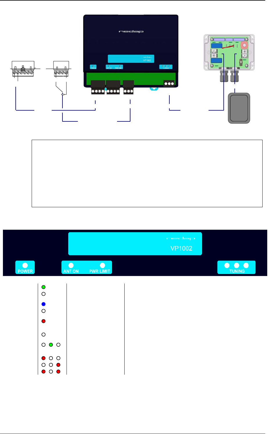
Cable specifications
A Min. 0.5 mm2 L.max 20m
B Coax RG 58 L.max 100m. Shield connected to minus.
C Coax RG 58 L.max 100m. Shield connected to minus.
D Standard antenna cable, do not change length of this cable
HDPE antenna types 50x50 art.no 9887881
40x120 art.no 9886095
60x100 art.no 9886257
LED indicators
POWER Green on Power on
Off No power
ANT ON Blue Antenna switch on by the SF4
Off Antenna switch off by the SF4
PWR LIMIT Red on Antenna power to high, reduce antenna power of the
SF4
Off Antenna power ok
TUNING /ID Green on
Green blinking
Antenna ok
Antenna ok and tag identified
Red on Antenna out of range
Red on Antenna out of range
Red blinking Antenna error
Antenna tuning
Set the SF4 in “id” mode. Turn with Lt in the antenna tuner untill the “tuning/id” led is green.
More details about the HDPE antenna tuner see also figure 3.
Fig. 4 Overview SF4 + Booster cable connections with walk-by ID
Single Feeder 4 - 16 - 10/2005 Version 0.2
3
2
1
4
5
6
7
8
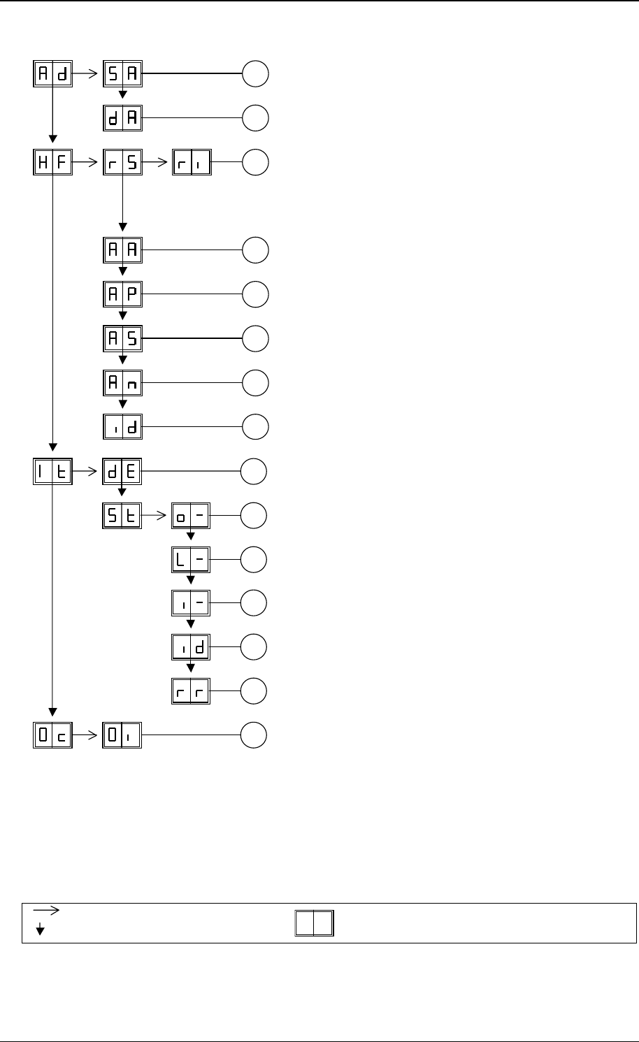
Fig. 5 Display menu
General overview, menu can be different for
prom types and versions
1. Set Address
2. Display Address
3. Responder select ri (iso)
Prom can not be used when ri is not available
4. Adjust Antenna, not used
5. Adjust Power
6. Adjust Squelch, not used
7. Not used
8. Test identification
A
B
F
D
E
C
G
A. Display errors
B. o1 motor output 1
o2 motor output 2
o3 motor output 3
o4 motor output 4
C. L1 output 1 (relais)
L2 output 2 (relais)
L3 output 3 (relais)
L4 output 4 (relais)
D. i1 input 1
i2 input 2
i3 input 3
i4 input 4
E. Test identification
F. ROM/RAM test / reboot
E1 ram error
E2 rom error
E3 ram and rom error
G. Output installation
Press button untill blinking
Press button short
To leave menu:
press button untill display is empty