Nedap N V SMARTDEACT Anti-Pilferage Device User Manual 14r01 Manual CGDSMARTDEACT
N. V. Nederlandsche Apparatenfabriek NEDAP Anti-Pilferage Device 14r01 Manual CGDSMARTDEACT
Contents
- 1. 14r01-Manual CGDSMARTDEACT
- 2. Users Manual
- 3. User manual
14r01-Manual CGDSMARTDEACT

Pulse Listen Deactivation
MANUAL SMARTDEACT
07 April 2014
This information is furnished for guidance, and with no guarantee as to its accuracy or completeness;
Its publication conveys no license under patent or other right, nor does the publisher assume
Liability for any consequence of its use; specifications and availability of goods mentioned in it are
Subject to change without notice; it is not to be reproduced in any way, in whole or in part, without the written consent of the
publisher.
© N.V. Nederlandsche Apparatenfabriek “Nedap”
EN
2
14r01-manual cgdsmartdeact.doc | Nedap Retail Support
Technical Support
E-Mail
info-rs@nedap.com
Postal address
N.V. Nederlandsche Apparatenfabriek “NEDAP”, Parallelweg 2, 7141DC, Groenlo, The Netherlands
Fax
+31 (0) 544-46 34 75
Safety precautions
CAUTION
RISK OF ELECTRIC SHOCK
DO NOT OPEN
CAUTION: TO REDUCE THE RISK OF ELECTRICAL SHOCK, DO NOT REMOVE COVER (OR BACK). NO
USER-SERVICEABLE PARTS INSIDE. REFER SERVICING TO QUALIFIED NEDAP SERVICE PERSONNEL.
Lightning flash with an arrowhead, enclosed in a triangle, alerts you to the
presence of uninsulated voltage points inside the product which could cause a
serious electrical shock.
An exclamation mark enclosed in a triangle alerts you to important operating and
maintenance instructions in the documentation provided with the product.
WARNING! To avoid the risk of fire or electrical shock, never expose these products to water or
operate in a high humidity environment.
EN 50419:2005
This European Standard specifies a marking
of electrical and electronic equipment in accordance with Article 11(2) of Directive 2002/96/EC
(WEEE); This is in addition to the marking requirement in Article 10(3) of this Directive which
requires producers to mark electrical and electronic equipment put on the market after 13
August 2005 with a ‘crossed-out wheeled bin’ symbol.
that applies to electrical and electronic equipment falling under Annex IA of Directive
2002/96/EC, provided the equipment concerned is not part of another type of equipment that
does not fall within the scope of this Directive. Annex IB of Directive 2002/96/EC contains an
indicative list of the products, which fall under the categories set out in Annex IA of this
Directive;
that serves to clearly identify the producer of the equipment and that the equipment has been
put on the market after 13 August 2005.
© 2009 N.V. Nederlandsche Apparatenfabriek “NEDAP” Parallelweg 2, NL-7141 DC Groenlo
The software / hardware described in this book / file is furnished under a license agreement and may be used only in accordance
with the terms of the agreement.
Copyright Notice
All Rights Reserved. Any technical documentation that is made available by N.V. Nederlandsche Apparatenfabriek “NEDAP” is the
copyrighted work of N.V. Nederlandsche Apparatenfabriek “Nedap” and is owned by N.V. Nederlandsche Apparatenfabriek
“Nedap”.

3
14r01-manual cgdsmartdeact.doc | Nedap Retail Support
No warranty
The technical documentation is being delivered to you and Nedap makes no warranty as to its accuracy or use. Any use of the
technical documentation or the information contained therein is at the risk of the user. Documentation may include technical or
other inaccuracies or typographical errors Nedap the right to make changes without prior notice. No part of this publication may
be copied without the express written permission of N.V. Nederlandsche Apparatenfabriek “Nedap” Parallelweg 2, NL-7141DC,
Groenlo, Netherlands.
Trademarks
Nedap, the Nedap logo, Nedap EASi/Net and the Nedap EASi/Net are registered trademarks of Nedap N.V. Nederlandsche
Apparatenfabriek “Nedap”
Other product names mentioned in this manual may be trademarks or registered trademarks of their respective companies and
are hereby acknowledged.
Printed in the Netherlands
Notice
The documentation is based in a Part numbers and Drawing number structure.
Part number can also be named as Artikel nummer or Article number
Drawing numbers can also be named as: Tekening
Drawing numbers are build up in a the drawing Number with a structure Txxxx-yyy-zz
Txxxx-yyy is the drawing number and extension number zz means:
10 is an overview drawing of the part and can contain wiring and circuit diagrams;
11 is the bill of material;
12 is the circuit diagram of the device.
Xxxx = 0000 – 9999
yyy = 000-999

4
14r01-manual cgdsmartdeact.doc | Nedap Retail Support
Table of content
1. Introduction 5
2. System overview 6
3. Wiring diagram 7
4. FCC Declarations 8
5. Specifications SMARTDEACT 9

5
14r01-manual cgdsmartdeact.doc | Nedap Retail Support
1 Introduction
N.V. Nederlandsche Apparatenfabriek “Nedap” further on called Nedap manufactures some of the most
reliable and scalable EAS Systems of the market today.
With this system your able to reduce the shoplifting costs the best in combination with Nedap’s tag line.
The SMARTDEACT is meant for Deactivation of disposable tags according to the Pulse Listen method.
It detects a tag in the field and shell try to deactivate it until it is not functioning anymore.
Some of the Smart Deactivator advantages are:
1. Constant optimal deactivation distance, independent of the tag frequency between 7.8 – 8.5
MHz
2. Different antenna sizes and shapes
3. Deactivation behavior programmable with switches
4. Detect only Mode
5. Deactivation on input
6. Forced deactivation on input
7. Short repeating acoustical feedback for successful deactivation, continue beep when
deactivation unsuccessful.
8. Prepared for connectivity in RS485 bus structure
9. Sends only a deactivation burst when a tag is detected
10. Through air synchronization with Nedap OS/T systems and other SMARTDEACT ‘s
11. Solid state output
The SMARTDEACT produces an acoustic and visual signal when it detects an operating tag and tries to
deactivate it.
6
14r01-manual cgdsmartdeact.doc | Nedap Retail Support
2 System overview
Power Adapter
-9651659
-9651608
Mains
SMART DEACTIVATOR
SMART DEAC
An tenna
Type: SDA-265x265
1
23
4
RS485 communication
Input
Output
5
6
7
LED
8
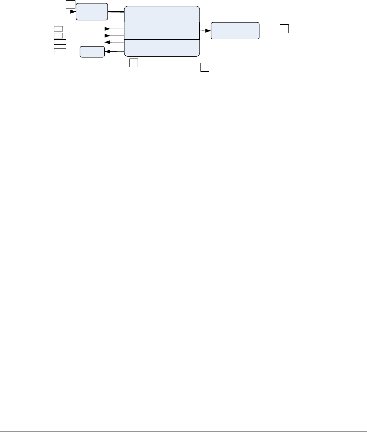
Figure 1 Functional system overview
The SMARTDEACT system consists of the following components:
1. AC/DC Power adapter Wall Mount 100 – 240 VAC / 12 VDC.
2. Smart Deactivator electronics
3. Antenna Cable
4. Antenna Type: SDA-265x265
5. RS485 connection to communicate with the SMARTDEACT
6. Input for to be defined functionality
7. Output to be defined functionality
8. LED for visual indication
The SMARTDEACT system is ready for use. You only have to follow the next steps:
• Install the Smart Deactivator system according the: Prospect SMARTDEACT;
• Power up the Smart Deactivator system;
• Check the functionality; by deactivating a Tag above the antenna and check the sound.
• Call Nedap Customer Support for quick hands-on problem solution in case of unforeseen
trouble (see Technical Support);
7
14r01-manual cgdsmartdeact.doc | Nedap Retail Support
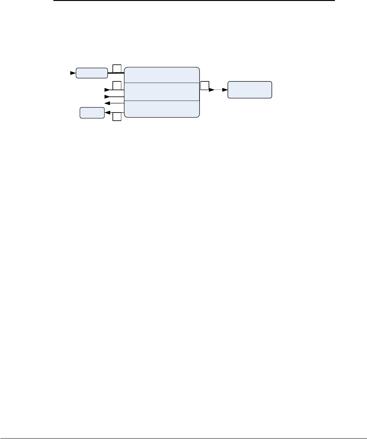
3 Wiring Diagram
Schematically diagrams below shows an example of the connections between used modules.
The picture shows the full configuration that can be built up.
Power AdapterMains
SMART DEACTIVATOR
Antenna
SMART DEAC
An tenna
SDA-265x265
DeactivatorPower adapter
1
2
3 4
RS485 communication
Input
Output
LED
The connections for a full configuration are:
1 DC power line
Connects 12VDC from the Power Adapter to the Electronics Unit
2 LED cable
Connects the SMARTDEACT to the LED unit
3 RS485 communication cable
Connects the SMARTDEACT to a RS485 host device for example a personal computer
4 Antenna cable
Connects the SMARTDEACT to the SDA-265x265 antenna

8
14r01-manual cgdsmartdeact.doc | Nedap Retail Support
4 FCC Declarations
Compliance statements (part15.19)
This device complies with part 15 of the FCC Rules and to RSS210 of Industry Canada.
Operating is subject to the following two conditions:
(1) this device may not cause harmful interference, and
(2) this device must accept any interference received, including interference that may cause
undesired operation.
Cet appareil se conforme aux normes RSS210 exemptés de license du Industry Canada.
L'opération est soumis aux deux conditions suivantes:
(1) cet appareil ne doit causer aucune interférence, et
(2) cet appareil doit accepter n'importe quelle interférence, y inclus interférence qui peut
causer une opération non pas voulu de cet appareil.
Warning (part15.21)
Changes or modifications not expressly approved by party responsible for compliance could
void the user’s authority to operate the equipment.
This in particular is applicable for the antenna which can be delivered with the
SMARTDEACT System.
RF Exposure (OET Bulletin 65)
To comply with FCC RF exposure requirements for mobile transmitting devices, this
transmitter should only be used or installed at locations where there is at least 20 cm
separation distance between the antenna and all persons.
Information to the User (Part 15.106(b))
Note: This equipment has been tested and found to comply with the limits for a class B
digital devices, pursuant to part 15 of the FCC Rules. These limits are designed to provide
reasonable protection against harmful interference in a residential installation. This
equipment generates, uses and can radiate radio frequent energy and, if not installed and
used in accordance with the instructions, may cause harmful interference to radio
communications.
However, there is no guarantee that interference will not occur in a particular installation. If
this equipment does not cause harmful interference to radio or television reception, which
can be determine by turning the equipment off and on , the user is encouraged to try to
correct the interference by one or more of the following measures:
- Reorient or relocate the receiving antenna.
- Increase the separation between the equipment and receiver.
-
Connect the equipment into an outlet on a circuit different from that to which the receiver
9
14r01-manual cgdsmartdeact.doc | Nedap Retail Support
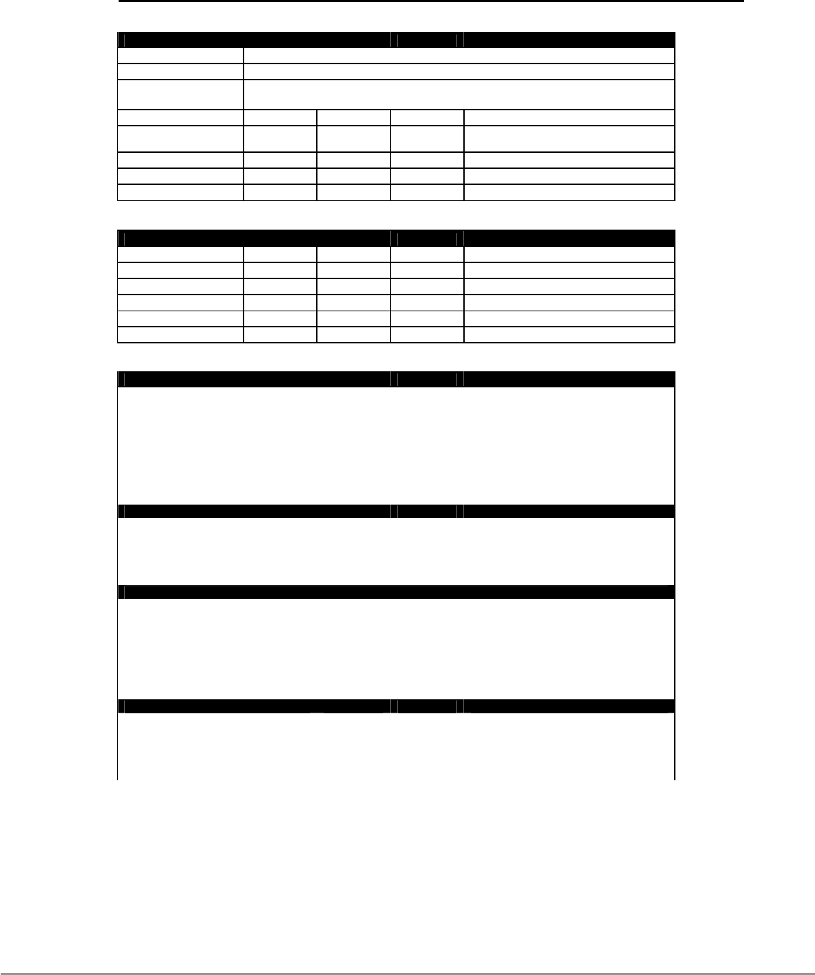
5 Specifications SMARTDEACT
Enviromental
Description
Material Construction Aluminium
Protection Class IP20
Min. Typical Max. Condition
Operating frequency 7.8 MHz 8.2 8.5 MHz
Operational
temperature 0°C 40 °C
Storage temperature -10°C +70°C
Relative Humidity 20% 90% non-condensing
Operating Distance 0.3m Antenna type dependant, Tag dependant
Input Requirements and electrical specifications
Description Min. Typical Max. Condition
Input Voltage 90VAC 100-240 264VAC Full Range; 50/60Hz
Input Current 0.35A - 0.7A 264VAC - 90VAC
Line Frequency 47 Hz 50-60Hz 63Hz -
Inrush Current @25°C 230VAC Cold Start
Operation Voltage 11.64VDC 12VDC 12.6VDC
Power 6W 230VAC 50Hz
Regulations
Safety approvals of the Power Adapter:
· cULus according to UL/CSA 60950-1
· CB according to IEC60950-1
· TUV EN60950-1 (2006)
· NEC Class 2 according to UL1310
· CE Europe according to EN60950-1
· Japan PSE
Telecom system approval
· Cannada IC ID according to RSS210 IC ID:1444A-SMARTDEACT
· US according to FCC Part 15 FCC ID:CGDSMARTDEACT
· CE according to EN300330
· Japan pending
In compliance with Human exposure assessment according to:
· EN62369-1 and EN50364
· ICNIRP Guidelines
· IEEE C95.1
· RSS102
· ARIB STD-38
· IEC62369-1
Electromagnetic compatibility
· EN 301 489 (Emission according to EN55022)
· IEC 61000-6-2
· IEC 61000-6-3
· CISPR 22