Nedap N V SMARTDEACT Anti-Pilferage Device User Manual
N. V. Nederlandsche Apparatenfabriek NEDAP Anti-Pilferage Device Users Manual
Contents
- 1. 14r01-Manual CGDSMARTDEACT
- 2. Users Manual
- 3. User manual
Users Manual

Smart Deactivator
Manual UL
manual smart deactivator
according to ul regulations
• SMART DEAC Mounting
• SMART DEAC Wiring
• Appendix 1 : Quick Reference
2
Technical Support
Email:
support-eas@nedap.com
Postal address:
N.V. Nederlandsche Apparatenfabriek “NEDAP”, Parallelweg 2, 7141DC, Groenlo, The Netherlands
Safety precautions:
CAUTION
RISK OF ELECTRIC SHOCK
DO NOT OPEN
CAUTION: TO REDUCE THE RISK OF ELECTRICAL SHOCK, DO NOT REMOVE COVER (OR BACK).
NO USER-SERVICEABLE PARTS INSIDE. REFER SERVICING TO QUALIFIED NEDAP SERVICE PERSONNEL.
ThisEuropeanStandardspeciesamarking
• of electrical and electronic equipment in accordance with Article 11(2) of Directive 2002/96/
EC (WEEE); This is in addition to the marking requirement in Article 10(3) of this Directive
which requires producers to mark electrical and electronic equipment put on the market
after 13 August 2005 with a ‘crossed-out wheeled bin’ symbol.
• that applies to electrical and electronic equipment falling under Annex IA of Directive
2002/96/EC, provided the equipment concerned is not part of another type of equipment
that does not fall within the scope of this Directive. Annex IB of Directive 2002/96/EC
contains an indicative list of the products, which fall under the categories set out in Annex
IA of this Directive;
• that serves to clearly identify the producer of the equipment and that the equipment has
been put on the market after 13 August 2005.
EN 50419:2005
© 2013 N.V. Nederlandsche Apparatenfabriek “NEDAP”:
Thesoftware/hardwaredescribedinthisbook/leisfurnishedunderalicenseagreementand
may be used only in accordance with the terms of the agreement.
Copyright Notice:
All Rights Reserved. Any technical documentation that is made available by N.V. Nederlandsche
Apparatenfabriek “NEDAP” is the copyrighted work of N.V. Nederlandsche Apparatenfabriek
“Nedap” and is owned by N.V. Nederlandsche Apparatenfabriek “Nedap”.

3
Table of content
1 Introduction 4
2 System overview 5
3 Installation instructions 6
4 Regulatory declaration 7
5 SpecicationsSMARTDEAC 8
6 Appendix 1 9

4
1 Introduction
N.V. Nederlandsche Apparatenfabriek “Nedap”, hereafter called “Nedap”, is manufacturer of one of the most
reliable and scalable EAS Systems in the market today.
With a Nedap EAS system you are able to reduce shoplifting costs to a minimum in combination with
Nedap’s tagging solutions.
TheNedapSmartDeactivator,alsocalledSMARTDEAC,ismeantfordeactivationofdisposable8.2MHzRF
labels.
It detects RF labels and hard tags in range of the deactivator antenna and tries to deactivate the rf labels until
they are deactivated.
Some of the Smart Deactivator advantages are:
1. Constantoptimaldeactivationdistance,independentofthetagfrequencybetween7.2–8.8MHz
2. Deactivation behavior programmable with switches
3. Detect only Mode
4. Deactivation on input
5. Forced deactivation on input
6. Short repeating acoustical feedback for successful deactivation, continuous beep when deactivation is unsuccessful or
when a hard tag is detected.
7. PreparedforconnectivityinRS485busstructure
8.Sends only a deactivation burst when a tag is detected; Low energy consumption
9. ThroughairsynchronizationwithNedapOS/TsystemsandotherSMARTDEAC‘s
The SMART DEAC produces an acoustic and visual signal when it detects and / or deactivates an operating RF
label or hard tag.
ANTENNA 275x275
SMART DEAC ANTENNA 265x265
5
2 System overview
SMART DEAC
Nedap Part.no. 9937676
Antenna
Model: SDA-265x265
Nedap Part.no.: 9564101
or
Model: DAPL-275x275
Nedap Part.no.: 9911537
Power Adapter
NedapPart.no.:9651802
LED
Nedap Part.no.: 9563652
Input
Output
RS485communication
1
7
6
5
2
43
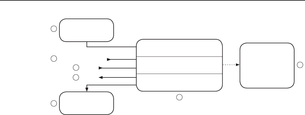
Figure 1 Functional system overview
The SMART DEAC system (Figure 1) consists of the following components:
1. AC/DCPoweradapterWallMount100–240VAC/12VDCNedapPart.no.:(9551802)
2. Smart Deactivator electronics (9937676)
3. Antenna including cable - Model: SDA-265x265 (9564101) or Model: DAPL-275x275 (9911537)
4. RS485connectiontocommunicatewiththeSMARTDEAC
5. Inputforfunctionalitytobedened
6. Outputforfunctionalitytobedened
7. LED for visual indication (9563652)
The SMART DEAC system is plug & play. You only have to follow the next steps:
• Install the Smart Deactivator system according the instructions;
• Power up the Smart Deactivator system;
• Check the functionality; by deactivating a RF label above the antenna and check it for a audio signal.
• Call Nedap EAS Support for quick hands-on problem solution in case of unforeseen trouble
(see Technical Support on page 2)

6
3 Installation instructions
The SMART DEAC electronics unit must be powered with a NEC class2 type power source like the NEDAP
AC/DCpoweradapter100~240Vac/12VdcNEDAPpartnumber9651802.
Always place the unit near a power outlet (less than 1 meter / 3.3 feet ), the power outlet should be easily
accessible, also after installation.
All the outputs from the SMART DEAC are NEC class2 outputs, output voltages will be 12Vdc or less.
The inputs may only be connected to class2 powered system.
TheSMARTDEACmustbemountedonasolid,nonammablesurface,usingallmountingholesandproper
mounting material, according to local regulations.
All wiring should be done according to local regulations.
External LED
An external LED can be connected to the connector pins marked LED + and -. We recommend the use of an
ULrecognizedLEDliketheAPEMredpanelmountindicatorledtypeQ14F1CXXR02.
(V_forward 1,6v +/-10% and I_forward max. 20mA)
The LED output is current limited and short-circuit protected.

7
4 Regulatory declaration
Compliance statements (part15.19)
This device complies with part 15 of the FCC Rules and to RSS210 of Industry Canada.
Operation is subject to the following two conditions:
(1) this device may not cause interference, and
(2) this device must accept any interference, including interference that may cause undesired operation of the
device.
Warning (part15.21)
Changesormodicationsnotexpresslyapprovedbythepartyresponsibleforcompliancecouldvoidthe
user’s authority to operate the equipment.
This in particular is applicable for the antenna which can be delivered with the SMART DEAC System.
RF Exposure (OET Bulletin 65)
To comply with FCC RF exposure requirements for mobile transmitting devices, this transmitter should only
beusedorinstalledatlocationswherethereisatleast20cm/8”separationdistancebetweentheantennaand
all persons.
Information to the User (Part 15.106(b))
Note: This equipment has been tested and found to comply with the limits for a class B digital devices,
pursuant to part 15 of the FCC Rules. These limits are designed to provide reasonable protection against
harmful interference in a residential installation. This equipment generates, uses and can radiate radio
frequent energy and, if not installed and used in accordance with the instructions, may cause harmful
interference to radio communications.
However, there is no guarantee that interference will not occur in a particular installation. If this equipment
causes harmful interference to radio or television reception, which can be determined by turning the
equipment off and on , the user is encouraged to try to correct the interference by one or more of the
following measures:
- Reorient or relocate the receiving antenna.
- Increase the separation between the equipment and receiver.
- Connect the equipment into an outlet on a circuit different from that to which the receiver is connected.
- Consult your local Nedap Business Partner or
- Consult the dealer of the radio communication device(s) or an experienced radio/TV technician for help.
8
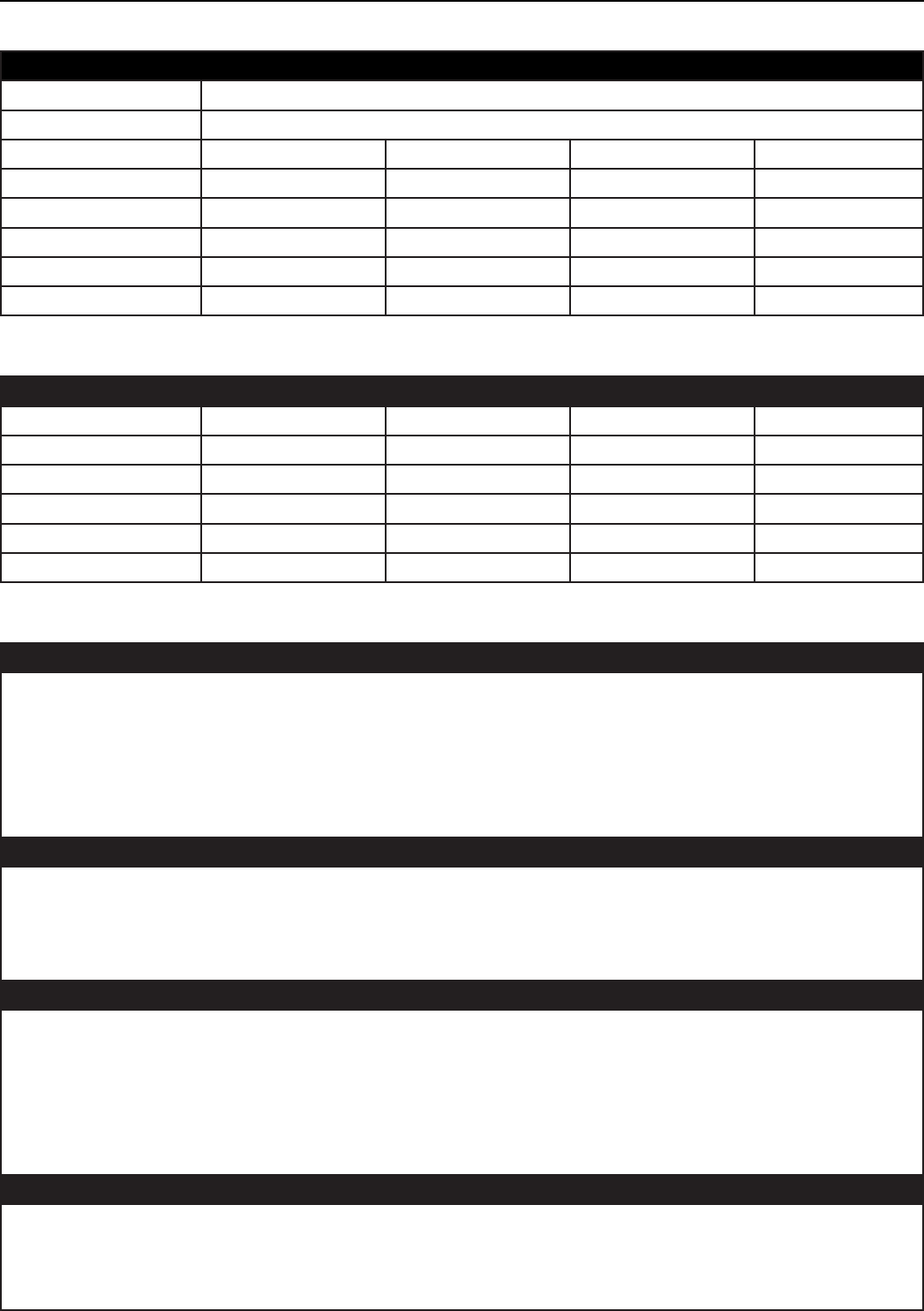
5 SpecicationsSMARTDEAC
Enviromental
Description
Material Construction Aluminium
Protection Class IP20
Min. Typical Max. Condition
Operating frequency 7.5MHz 8.2MHz 8.8MHz
Operational temperature 0 ºC / 32 °F 40 ºC / 104 °F
Storage temperature -10 ºC / 14 °F +70ºC/158°F
Relative Humidity 20 % 90 % non-condensing
Operating Distance 0.3 m / 12” Tag-dependant
InputRequirementsandelectricalspecications
Description
Min. Typical Max. Condition
Input Voltage 90 VAC 100-240 264 VAC FullRange;50/60Hz
Input Current 0.35 A -0.7 A 264 VAC - 90 VAC
Line Frequency 47Hz 50-60Hz 63Hz -
Operation Voltage
Power 3 W 230VAC50Hz
Regulations
Safety approvals of the Power Adapter
• cULus according to UL/CSA 60950-1
• CB according to IEC60950-1
• TUV EN60950-1 (2006)
• NEC Class 2
• CE Europe according to EN300330
• Japan PSE
Telecom system approval
• Canada IC according to RSS210 IC ID:1444A-SMARTDEAC
• US according to FCC Part 15 FCC ID:CGDSMARTDEAC
• CE according to EN300330
• Japan pending
In compliance with Human exposure assessment according to:
• EN62369-1 and EN50364
• ICNIRP Guidelines
• IEEE C95.1
• RSS102
• ARIBSTD-38
• IEC62369-1
Electromagnetic compatibility
• EN301489(EmissionaccordingtoEN55022)
• IEC 61000-6-2
• IEC 61000-6-3
• CISPR 22
9
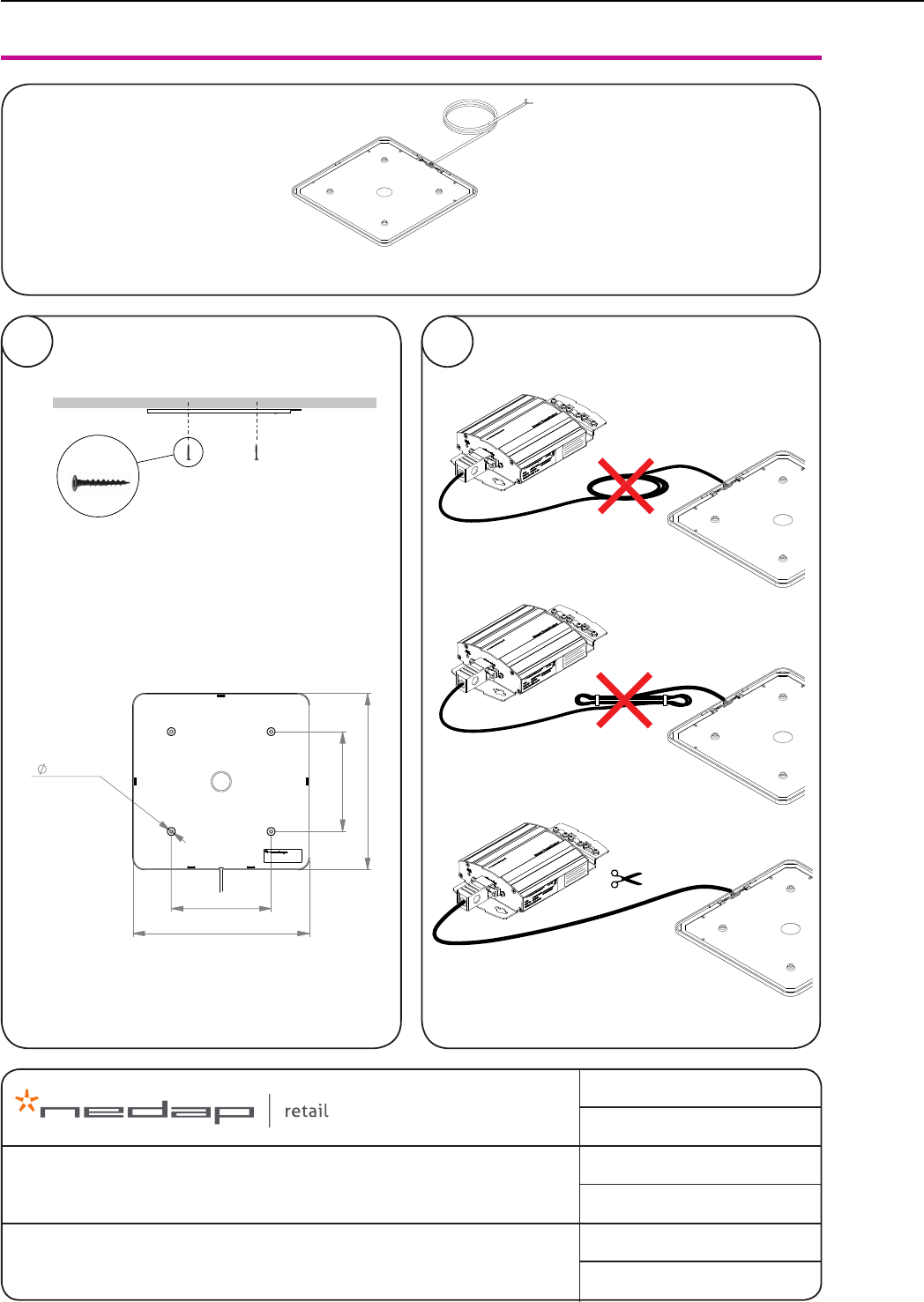
6 Appendix 1
02
Deactivator Antenna 265x265
01
Deactivator Antenna 265 x 265 (cable length 1600 mm)
GROENLO
THE NETHERLANDS
Copyright © by N.V. Nederlandsche Apparatenfabriek NEDAP. No part of this drawing may be
reproduced or distributed in any form or by any means, or stored in a data base or retrieval system
without the prior written permission of NEDAP.
article no
date
rev
dsgn
page
drawing
quick reference : antenna 265x265
: 27 February 2014 12:08 PM
: CB
: A
: 1 of 1
: T9741704-45.01
: 9741704
Table
Bottom mount
4x , not included
150
4,5 (4x)
150
265
265
150
4,5 (4x)
150
265
265
10
Copyright © by N.V. Nederlandsche Apparatenfabriek NEDAP. No part of this drawing
may be reproduced or distributed in any form or by any means, or stored in a data base or
retrieval system without the prior written permission of NEDAP.
description:
quick ref. Smart Deactivator | art. no. 9200002
doc. article no: 5276802
chk:
drw: CB 2013/05/29
sheet: 45.01 of 1
drawing: T9937-676
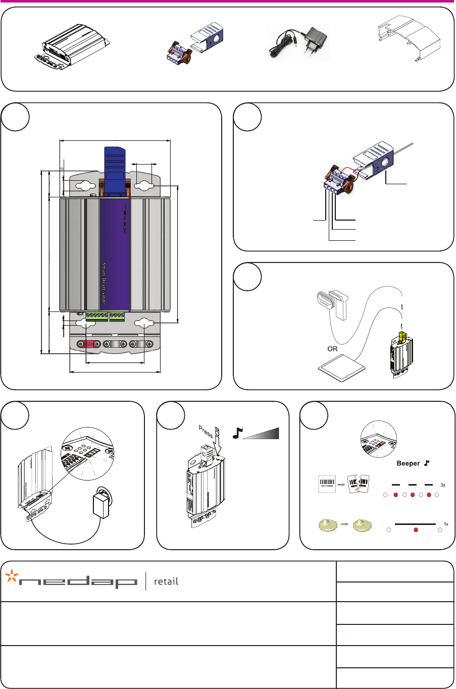
1x Smart Deactivator including power supply
Smart Deactivator
1x Antenna connector set
05 Beeper sound volume
04 Connect to power 100-240V
deactivation
detection
06 Beeper sound (Standard mode)
56
40.5 25
175.3
106
14.5
86.6
131.6
10
4.5
109.8
01
ANT Antenna wire 2
GND Ground
GND Ground
ANT Antenna wire 1
Tie Wrap
to deactivator
antenna
ANT1
ANT2
02 Connect deactivator antenna to antenna
connector
Mount housing to solid surface
03 Connect deactivator antenna to Smart
Deactivator
1x Connector cover1x Power Supply
Rev. : B.03
GROENLO - HOLLAND
11
90 seconds
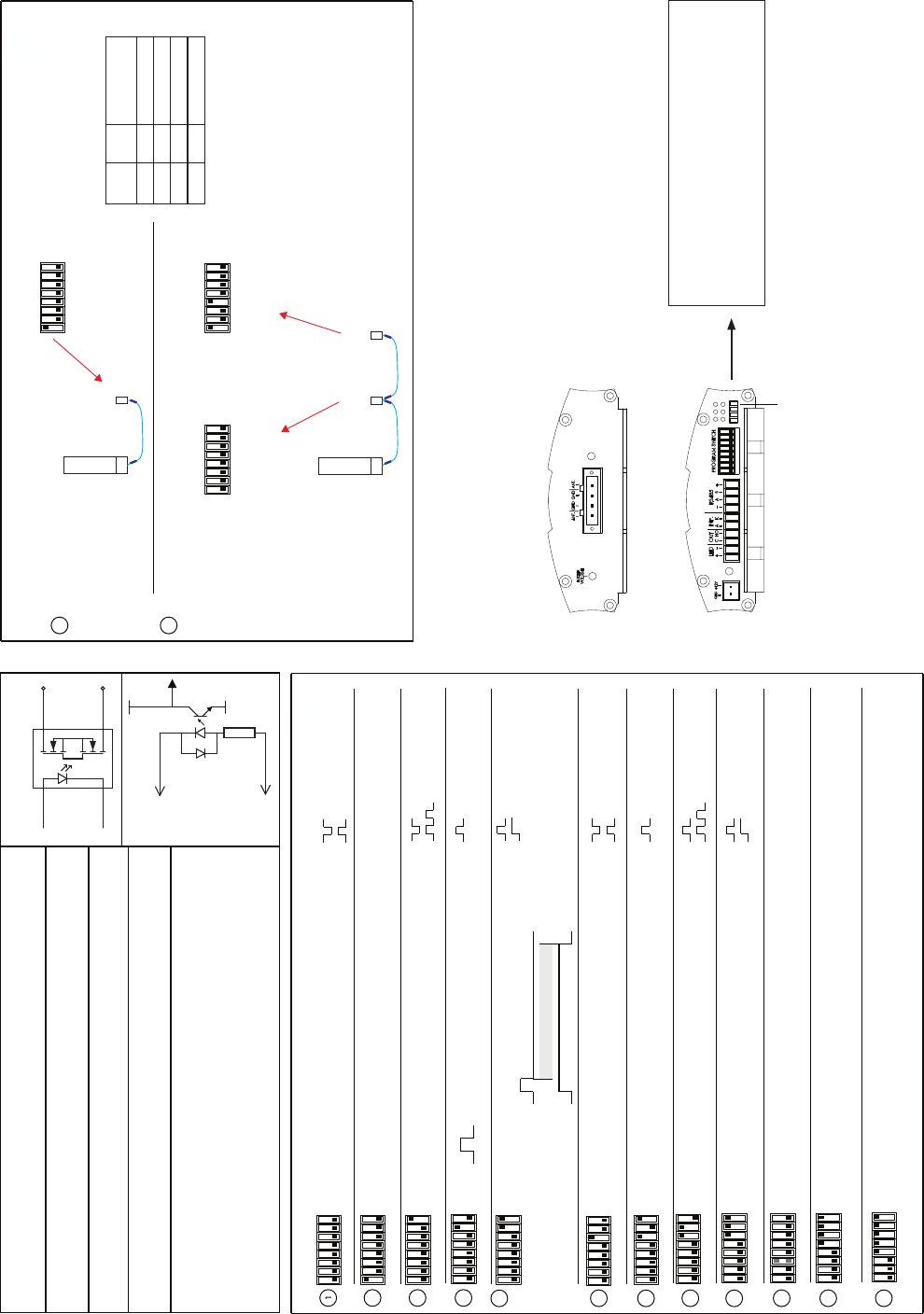
Program Switch settings (current version v6.8, version label on bottom of unit)
GND Power connector Ground
+12V Power Connector +12V DC S
+S
G3VM-351A
OC1
Out C Output Common Solid State Output
Out NO Normal Open
Inp A Input Anode 5 - 12V
Inp K Input Kathode
+12V + It is possible, by using a special
RS485 A RS485 Connector A RS485 converter and software, to
RS485 B RS485 Connector B adjust some settings.
GND -
LED + LED Output Connector + The LED will flash 3x at deactivation
LED - LED Output Connector - and once on detection.
Solid State Output
Input
Kathode (-)
Anode (+)
GND
LED Yellow Low after deactivation
LED Orange High at input signal
LED Yellow Low after detection
LED Orange Flash
LED Yellow High after 10 seconds detection
LED Orange not used
LED Yellow High after 10 seconds detection
LED Orange High during deactivation
LED Yellow low after deactivation
LED Orange High at input signal
LED Yellow High pulse after deactivation
LED Orange not used
LED Yellow High pulse after detection
LED Orange Flash
2
3
4
5
6
7
8
LED Yellow High pulse after detection
LED Orange High during deactivation
9
10 Low = Standard sensitivity
High = Low sensitivity (Software > 6.4)
1 2 3 4 5 6 7 8
1 2 3 4 5 6 7 8
1 2 3 4 5 6 7 8
Standard mode
Line Termination RS485
1 2 3 4 5 6 7 8
1 2 3 4 5 6 7 8
Detect only mode
1 2 3 4 5 6 7 8
1 2 3 4 5 6 7 8
Output after 10 seconds of detection
Forced deactivation, for 90 seconds after input signal
1 2 3 4 5 6 7 8
1 2 3 4 5 6 7 8
1 2 3 4 5 6 7 8
1 2 3 4 5 6 7 8
1 2 3 4 5 6 7 8
Input used as switch for buzzer volume
Counting output inverted - Standard mode
Detect only - Output inverted
Deactivation only if input is high ( software > 6.3 )
12
11 ( software V7.0 )
( software V7.0 ) 4 = low Address 1 (standard)
4 = high Address 2
DLL mode - Transaction Controlling
Status LEDs
Green = Power
Red = Label detected – 1 flash (Standard mode)
Label deactivated – 3 flashes (Standard mode)
Yellow = Output LED
Orange = Status LED
Depending on dipswitch settings, LED behaviour can be different. (See Program switch settings)
1 2 3 4 5 6 7 8
13
14
1 = Line Termination RS485
4 = Low Address 1
i37
Smart-
Deactivator
i37
Smart-
Deactivator 1
Smart-
Deactivator 2
1 2 3 4 5 6 7 8 1 2 3 4 5 6 7 8
1 = No Line Termination
4 = Low Address 1
1 = Line Termination RS485
4 = High Address 2
Smart-
Deactivator 1
Smart-
Deactivator 2
Renos
RS485
Smart deactivator
RS485
+12V +
AB
BA
GND -
1 2 3 4 5 6 7 8
Status LEDs
Antenna connector side
Connector side
Version: >V7.5
Version: >V7.6
Settings only for use with !Sense
Program Switch settings

parallelweg 2d
nl-7141 dc groenlo
the netherlands
t
f
e
i
+31 (0) 544 471555
+31 (0) 544 465814
info-rs@nedap.com
www.nedap-retail.com
2014 - v1