Nedap N V SMARTDEACT Anti-Pilferage Device User Manual
N. V. Nederlandsche Apparatenfabriek NEDAP Anti-Pilferage Device Users Manual
UserManual.wiki
>
Nedap N V
>
SMARTDEACT User Manual
>
Users Manual
Contents
1.
14r01-Manual CGDSMARTDEACT
2.
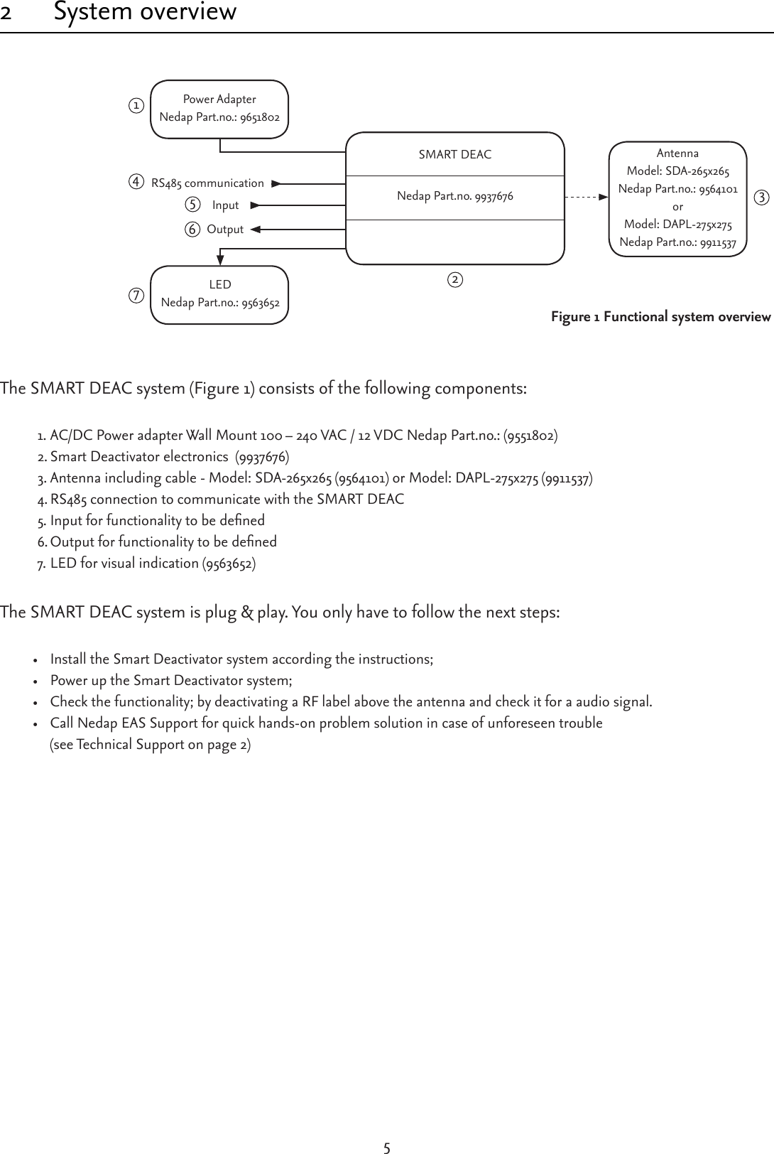
Users Manual
3.
User manual
Users Manual
Navigation menu
Upload a User Manual
Namespaces
Wiki Guide
HTML
PDF
Info
Views
User Manual
Discussion / Help
Navigation