Nedap N V STOREIDT UHF RFID reader User Manual 14r01 9954139 QR T ID Top Version B01 CGDSTOREIDT
N. V. Nederlandsche Apparatenfabriek NEDAP UHF RFID reader 14r01 9954139 QR T ID Top Version B01 CGDSTOREIDT
14r01_9954139-QR-T-ID Top- Version B01 CGDSTOREIDT
Copyright © by N.V. Nederlandsche Apparatenfabriek NEDAP. No part of this drawing may be repro-
duced or distributed in any form or by any means, or stored in a data base or retrieval system without the
prior written permission of NEDAP.
description:
quick reference !D Top
doc. article no: 5279615
chk:
rev. : B.01
drw: CB 2013/05/29
sheet: 45.01 of 1
drawing: T5279-615
!D Top
-
A
YYYY-MM-DD
Documentation released
-
Ref.Nr.
REV.
DATE
DESCRIPTION
APPROVED
N/A
DIM. IN MM
ROUGHNESS ACC.
ISO 1302 in µM
GENERAL TOLERANCES
SCALE:
FORMAT:
DRAWING:
Copyright (c) by N.V. Nederlandsche Apparatenfabriek NEDAP. No part of this
drawing may be reproduced or distributed in any form or by any means, or stored
in a data base or retrieval system without the prior written permission of NEDAP.
A
B
C
D
E
F
6
3
2
1
F
E
D
C
B
A
5
6
7
8
A3
9954139
N/A
A.01
ARTICLE NUMBER
REV.
ISO A
GROENLO HOLLAND
SHEET:
4
7
8
5
4
3
2
1
10.01 OF 1
1:5
± 1°
± 0.2
DESCRIPTION
LIN.
ANG.
N/A
??
??
??
DRW:
CHCK:
YYYY-MM-DD
YYYY-MM-DD
YYYY-MM-DD
DSGN:
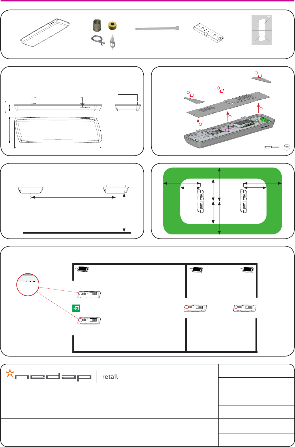
=150=
6,5(3x)
35
50
5
8
7
7
196,5
Holes, for excample:
- Fixing bracket at the ceiling
- Using wire rod(s)
For hanging on
the antenna with
hook (for excample)
65
84,5
500
198,5
900
265
50(4x)
35(4x)
7(4x)
7(4x)
4(8x)
5
8(4x)
DETAIL A
SCALE 1 : 2
Weight of antenna: 4 kg
1x !D Top
dimensions remove cover 1
2
2
2
1
1
distance between antennas
oor
-
A
YYYY-MM-DD
Documentation released
-
Ref.Nr.
REV.
DATE
DESCRIPTION
APPROVED
N/A
DIM. IN MM
ROUGHNESS ACC.
ISO 1302 in µM
GENERAL TOLERANCES
SCALE:
FORMAT:
DRAWING:
Copyright (c) by N.V. Nederlandsche Apparatenfabriek NEDAP. No part of this
drawing may be reproduced or distributed in any form or by any means, or stored
in a data base or retrieval system without the prior written permission of NEDAP.
A
B
C
D
E
F
6
3
2
1
F
E
D
C
B
A
5
6
7
8
A3
9954139
N/A
A.01
ARTICLE NUMBER
REV.
ISO A
GROENLO HOLLAND
SHEET:
4
7
8
5
4
3
2
1
10.01 OF 1
1:5
± 1°
± 0.2
DESCRIPTION
LIN.
ANG.
N/A
??
??
??
DRW:
CHCK:
YYYY-MM-DD
YYYY-MM-DD
YYYY-MM-DD
DSGN:
-
A
YYYY-MM-DD
Documentation released
-
Ref.Nr.
REV.
DATE
DESCRIPTION
APPROVED
N/A
DIM. IN MM
ROUGHNESS ACC.
ISO 1302 in µM
GENERAL TOLERANCES
SCALE:
FORMAT:
DRAWING:
Copyright (c) by N.V. Nederlandsche Apparatenfabriek NEDAP. No part of this
drawing may be reproduced or distributed in any form or by any means, or stored
in a data base or retrieval system without the prior written permission of NEDAP.
A
B
C
D
E
F
6
3
2
1
F
E
D
C
B
A
5
6
7
8
A3
9954139
N/A
A.01
ARTICLE NUMBER
REV.
ISO A
GROENLO HOLLAND
SHEET:
4
7
8
5
4
3
2
1
10.01 OF 1
1:5
± 1°
± 0.2
DESCRIPTION
LIN.
ANG.
N/A
??
??
??
DRW:
CHCK:
YYYY-MM-DD
YYYY-MM-DD
YYYY-MM-DD
DSGN:
3x Tie-wrap4x Mounting set 2x Bracket (wall mounting)
GROENLO - HOLLAND
sales oor stock room
orientation in the shop
all antennas
in the same
direction.
Power inserter
recommended - 2.0m/6.6ft
absolute max. - 2.4m/7.9ft
recommended - 3.0m/9.8ft
absolute max. - 3.5m/11.5ft
recommended label free zone
required label free zone
500mm / 1.6ft
900mm / 3ft
198.5mm / 7.8”
265mm / 10.4”
84.5mm / 3.3”
65mm / 2.6”
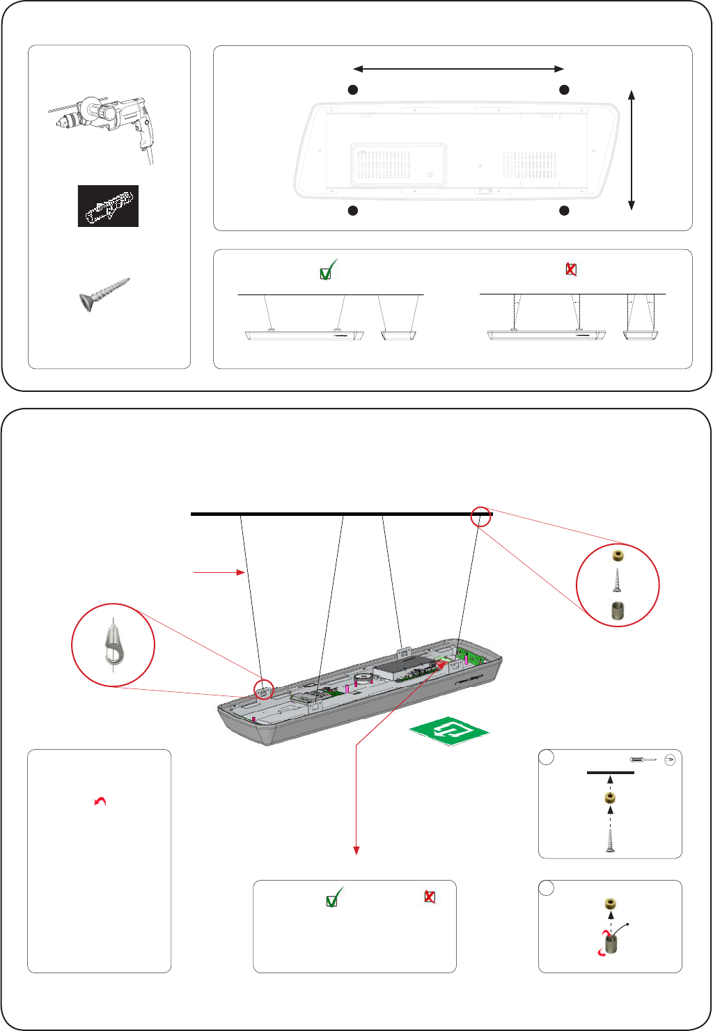
!D Top mounting template for ceiling
The !D top is most stable when the wires form a
broader basis (see picture on the right).
To make this mounting template more rigid
use the cardboard packaging of the !D top
steps for mounting !D Top on the ceiling
1. determine the position of the !D top in store
2. measure the height between !D top and ceiling
3. find the corresponding mounting holes on this
template, closest to the measured height
4. position this template to the ceiling and mark the
four mounting holes (pierce through the paper)
5. drill the holes, connect the cables and the !D top
height max. 150 cm
height max. 100 cm
height max. 50 cm
height max. 25 cm
height max. 200 cm
height max. 250 cm
height max. 150 cm
height max. 100 cm
height max. 50 cm
height max. 25 cm
height max. 200 cm
height max. 250 cm
height max. 150 cm
height max. 100 cm
height max. 50 cm
height max. 25 cm
height max. 200 cm
height max. 250 cm
height max. 150 cm
height max. 100 cm
height max. 50 cm
height max. 25 cm
height max. 200 cm
height max. 250 cm
h
part no. 9741291
drawing no. t9741-291a
1x Poster
2m / 6ft 2m / 6ft
2m / 6ft2m / 6ft
1m / 3ft1m / 3ft
1m / 3ft 1m / 3ft
ceiling
steel-cable
steel-cable
02
01
ceiling
not included
adjust height
press here.
!D Top ceiling installation
drilling holes (poster recommended)
90mm / 3.5”
ø 13mm / ø 0.5”
6 mm
ceiling 520
220
4x plugs S6 (recommended)
4x screw 4x40 (recommended)
included
top-view
(not included)
520mm / 1.7ft
220mm / 8.7”
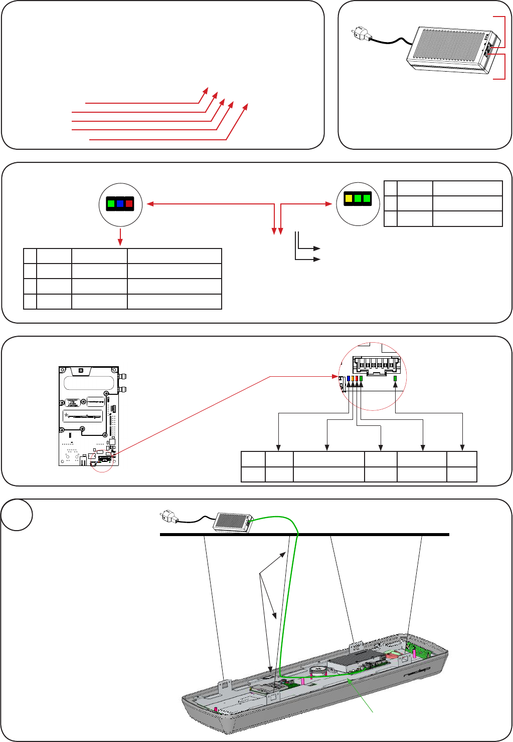
processing unit
network IN
network OUT
USB service port
USB host
ceiling
power-supply OUT
unit - network IN
mounting power cable
x cable with
tie-wrap
installation of
one !D Top
01
Power for Reader
1 Yellow Heartbeat
2 Green Disk access
3 Green Firmware running
1 2 3
+
-buzzer
C
D
E
F
10
7
2
1
F
E
8
11
12
9
3
4
5
6
G
H
G
H
C
D
E
F
10
7
2
1
F
E
8
11
12
9
3
4
5
6
G
H
G
H
Led Blue Orange Red Green Green
-Firmware running Error RFID active Power
next
previous
!D Reader
1 Green Processing unit at output
2 Blue Blink No device at output
Blue Continuous Power inserter at output
3 Red Power error
Recommended to place in switch-room
power supply Out
In
Power supply 9561811. One needed for
every installed system. (not included)
Not compatible with IEEE 802.3a* standard
note:
use only cat5e ethernet cable or better,
with all 8 wires connected.
!D-Top - 1
230V
110V
connect voltage supply
01
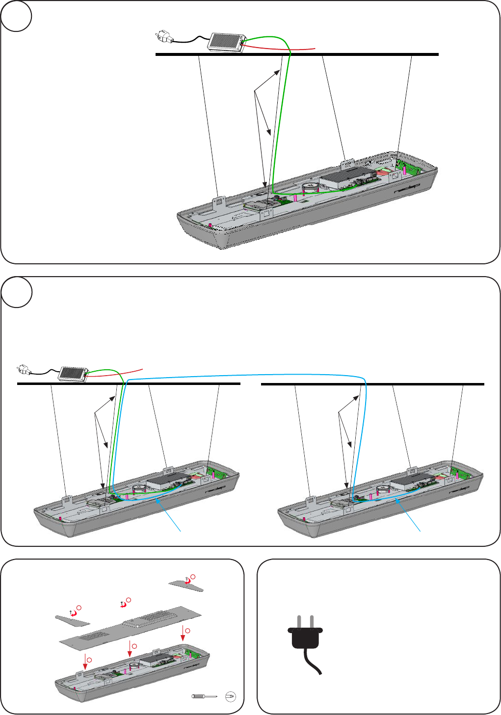
Note :
The start up of all the
processes takes
approximately 3 minutes.
place cover
1
2
2
2
1
1
ceiling
x cable with
tie-wrap
RJ45 connector to ethernet
outlet - customer network.
x cable with
tie-wrap
unit - network OUT unit - network IN
installation of
two !D Tops
ceiling
RJ45 connector to ethernet
outlet - customer network.
mounting ethernet cable
02
x cable with
tie-wrap
installation of
one !D Top
!D-Top - 2
note:
use only cat5e ethernet cable or better,
with all 8 wires connected.
note:
use only cat5e ethernet cable or better,
with all 8 wires connected.

Model: !D Top Region 2
FCC ID: CGDSTOREIDT IC: 1444A-STOREIDT
Model: !D Top Region 2
FCC ID: CGDSTOREIDT IC: 1444A-STOREIDT
This device complies with part 15 of the FCC Rules and to RSS210 of Industry Canada. Operation is subject to the following
two conditions:
(1) this device may not cause harmful interference, and
(2) this device must accept any interference received, including interference that may cause undesired operation.
Changes or modications not expressly approved by the party responsible for compliance could void the user’s
authority to operate the equipment.
Cet appareil se conforme aux normes RSS 210 exemptés de license du Industry Canada.
L’opération est soumis aux deux conditions suivantes:
(1) cet appareil ne doit causer aucune interférence, et
(2) cet appareil doit accepter n’importe quelle interférence, y inclus interférence qui peut causer une opération non pas voulu
de cet appareil.
Les changements ou modications n’ayant pas été expressément approuvés par la partie responsable de la conformité peuvent
faire perdre à l’utilisateur l’autorisation de faire fonctionner le matériel.
FCC and IC Radiation Exposure Statement:
This equipment complies with FCC and Canadian radiation exposure limits set forth for an uncontrolled environment. This
equipment should be installed and operated with a minimum distance of 22 cm between the radiator and your body. This
transmitter must not be co-located or operating in conjunction with any other antenna or transmitter.
Cet équipement est conforme a RSS-102 limites énoncées pour un environnement non contrôlé. Cet équipement doit être
installé et utilisé avec une distance minimale de 22 cm entre le radiateur et votre corps.
This Class B digital apparatus complies with Canadian ICES-003
Cet appareil numérique de Classe B est conforme à la norme Canadienne ICES-003
NOTE: This equipment has been tested and found to comply with the limits for a Class B digital device, pursuant to part 15
of the FCC Rules. These limits are designed to provide reasonable protection against harmful interference in a residential
installation. This equipment generates, uses and can radiate radio frequency energy and, if not installed and used in
accordance with the instructions, may cause harmful interference to radio communications. However, there is no guarantee
that interference will not occur in a particular installation.
If this equipment does cause harmful interference to radio or television reception, which can be determined by turning the
equipment off and on, the user is encouraged to try to correct the interference by one or more of the following measures:
- Reorient or relocate the receiving antenna.
- Increase the separation between the equipment and receiver.
- Connect the equipment into an outlet on a circuit different from that to which the receiver is connected.