Nedap N V T325RRFMD ASSY T325R RF+MD User Manual Manual
N. V. Nederlandsche Apparatenfabriek NEDAP ASSY T325R RF+MD Manual
Manual
ASSY T325R RF IR
Copyright © by N.V. Nederlandsche Apparatenfabriek NEDAP. No part of this drawing may be reproduced or distributed
in any form or by any means, or stored in a data base or retrieval system without the prior written permission of NEDAP.
item
date
revision
dsgn
document
Quick reference : ASSY T325R RF IR
: 15 September 2017 10:41 AM
: CvdB
: A.02
: T9565795-45.01
: 9565795
N.V. Nederlandsche Apparatenfabriek “Nedap”
Parallelweg 2, NL-7141 DC Groenlo (The Netherlands)
Mail: support-retail@nedap.com
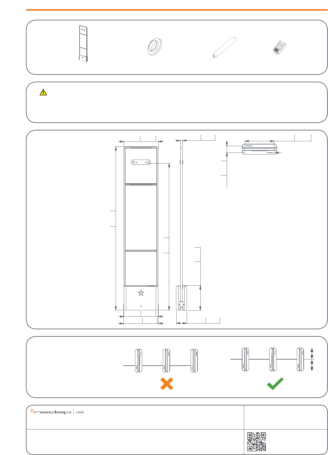
1x | ASSY T325R RF
dimensions
2x | lter 2x | connector RJ454x | insullation ring
325mm
1'0.80"
322mm
1'0.68"
1534.3mm
5'0.41"
328.6mm
1'0.94"
1378.3mm
4'6.26"
(Customer counter)
20mm
0.79in
231.7mm
9.12in
97.7mm
3.85in
60mm
2.36in
277,5mm
10.93in
Mounting holes
Use M10-studs
This equipment should be installed, operated, serviced, and repaired by qualied personnel only. The installation and interconnection of this equipment to facility wiring and other
equipment must be done by a competent, qualied craftsperson who is familiar with applicable standards and codes governing the installation. Installation methods, practices, or
procedures that are unauthorised or done improperly are dangerous and could result in serious personal injury or damage to property and equipment.
conduit or slit
(topview)
Warning
Preliminary
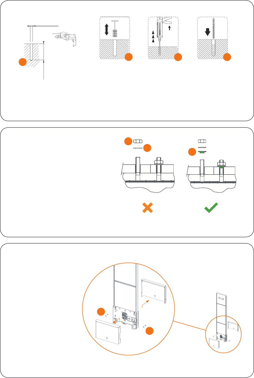
90mm / 3.5”
ø 13mm / ø 0.5”
2
drill the hole
Ø 13 mm (Ø 0.5in)
90 mm (3.5in)
3
1
2
1 Nut M10 (not included in installation set)
2 Retainer ring M10 (not included in installation set)
3 Nylon insulation ring M10 (included in installation set)
always use a nylon insulation ring
4
23
1 Drill the hole
2 Clean the hole
3 Insert Hilti-hit
4 Place the nut
1
remove covers
1
1
1 Screw M3x10
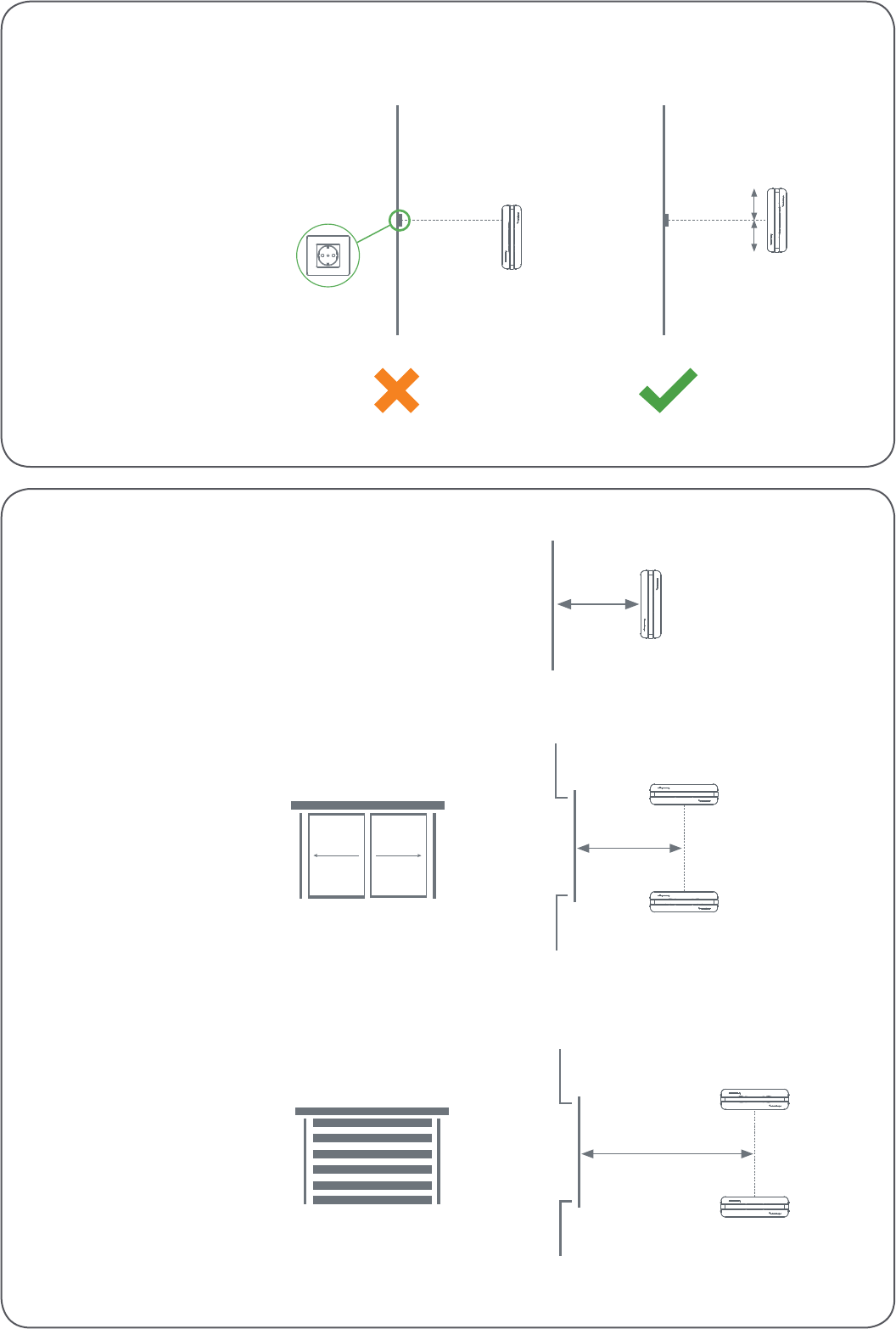
> 70 cm (27.6 in.)
> 40 cm (15.8 in.)
distance to roller shutter (RF)
> 20 cm (7.9 in.)
distance to a normal door or sliding door (RF)
distance to the wall (RF)
> 20 cm (7.9in)
> 40 cm (15.8in)
> 70 cm (27.6in)
place near to a wallsocket (RF)
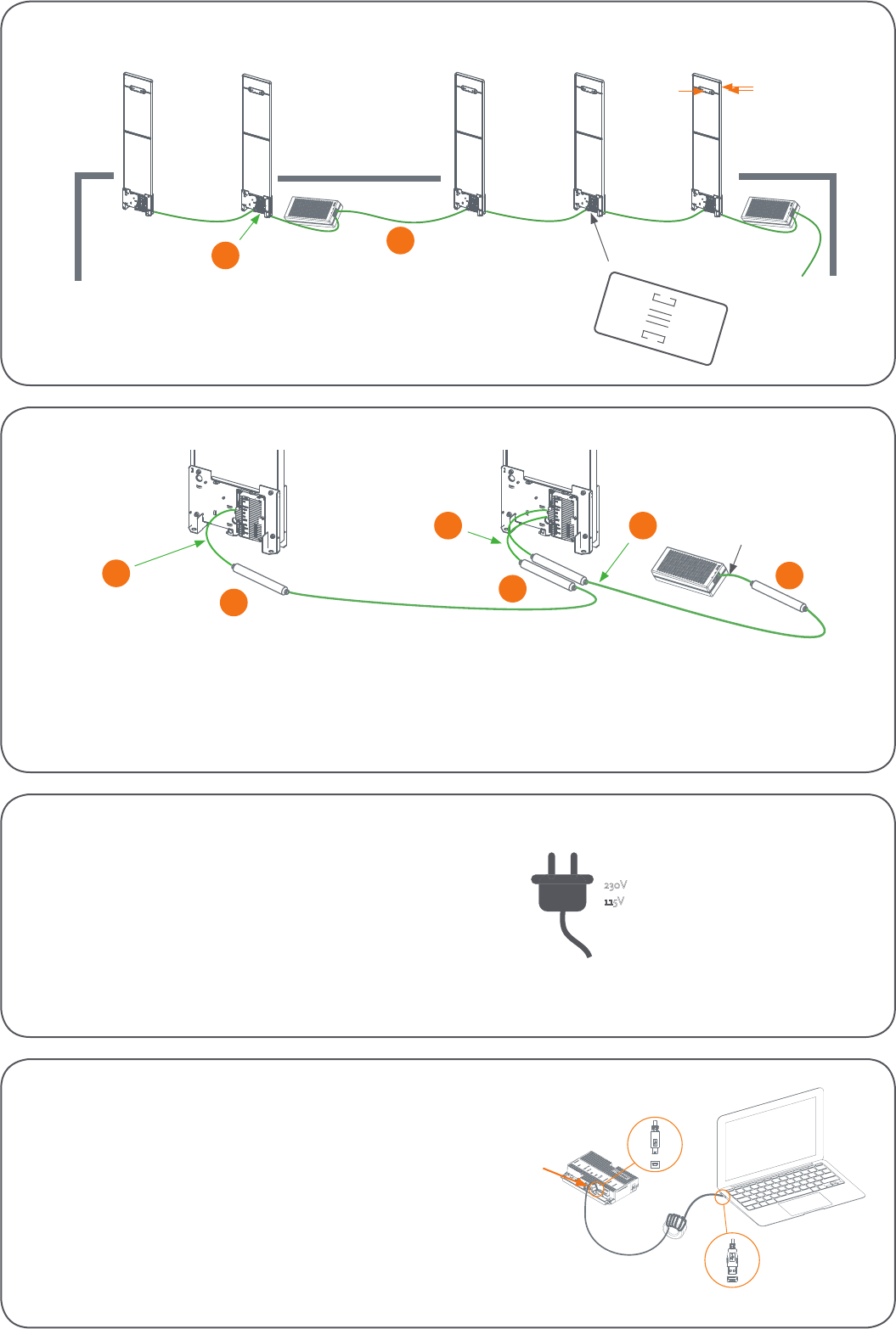
P.I. > network OUT
Installation
orientation:
Store exit (EAS)
Sales oor (SRSF)
Stockroom (GR)
Sales oor (EAS)
Stockroom (SRSF)
Loading bay (GR)
IN previous
OUT next
lters
cabling
1
1 Ethernet cable
2 Renos side
1 Filter
2 Renos network IN
3 Renos network OUT
111
2
23
Tx Rx
power system
Plug the Power Inserter into the socket.
230V
115V
INPORTANT:
Network should be connected in the “network setup”-step of the installation wizard.
Do not connect a network to !Sense before power up!
NOTE:
Start up takes
approximately 3 minutes.
connecting a laptop to the Renos unit
Renos - Service port
Attach your laptop to one of the Renos units with a mini USB-USB cable.
Open the browser on your laptop and go to:
http://192.168.133.1
Congure the system using the installation wizard.
2
place covers
1 Screw M3x10
1
1
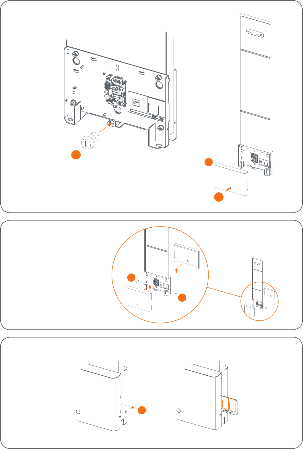
place keyswitch
1
1 Remove cover
2 Push to remove small metal part
3 Place keyswitch (can be placed on both sides of the antenna)
(optional)
3
2
label information
1
1 Pull to see the label information (Two labels at the front side and one at the back side)
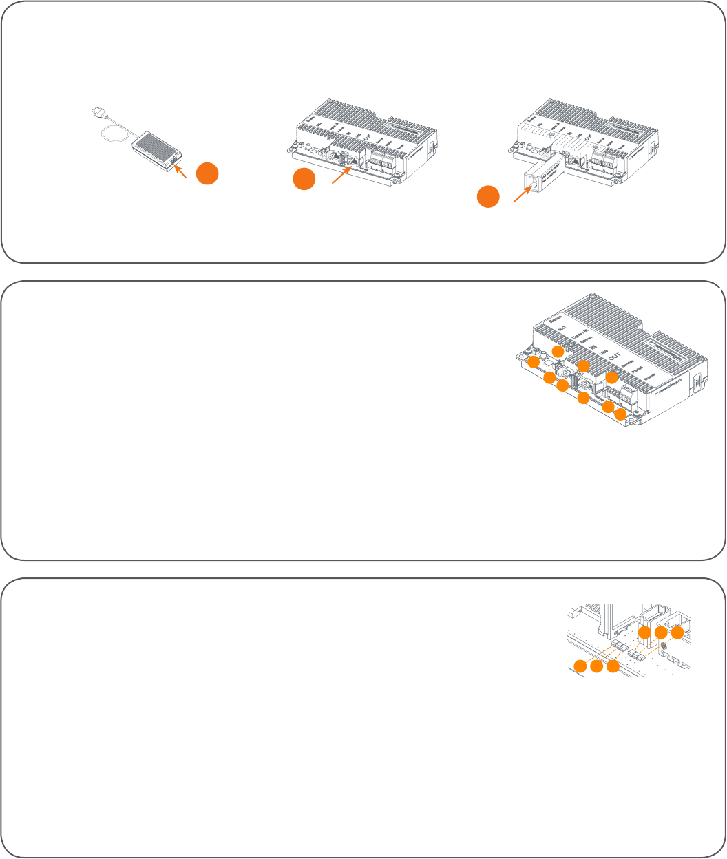
status LEDs Renos
1
1 2 3
456
1 Green On There is a Renos unit connected to the OUT port of this unit
O There is no Renos unit connected to the OUT port of this unit
2 Blue Blinking There is no device connected to the OUT port of this unit
On There is a Power Inserter connected to the OUT port of this unit
3 Red On There is an issue with the power supply at the OUT port of this unit (too little current drawn)
Blinking There is an issue with the power supply at the OUT port of this unit (too much current drawn)
O There is no issue with the power supply at the OUT port of this unit
4 Yellow Blinking The operating system on the Renos unit is running
O The operating system on the Renos unit is not running
5 Green Blinking The storage ash on the Renos unit is accessed
O The storage ash on the Renos unit is not accessed
6 Green On The rmware on the Renos unit is running
O The rmware on the Renos unit is not (yet) running
Renos
1
2
3
4
5
6
7
8
9
1 50Ω Connect to the 50Ω PCB from the antenna.
2 Lights / IR Connect to the lights and customer counting.
3 Add-on Provide power and synchronisation to add-ons, like the RFID reader.
4 Network IN Connected to the Network OUT of a previous Renos unit or a Power Inserter.
5 USB Connect accessories to Renos, like the RFID reader or USB network adapter.
6 Network OUT Connected to the Network IN of a previous Renos unit or a Power Inserter.
Can also be left unconnected or connected to the customer network.
7 Mini USB service port Connect your laptop to congure the Renos system.
8 RS485 connector Connect to the smart deactivator(s).
9 Buzzer connector Connect to the buzzer.
Caution:
Risk of Explosion if Battery is replaced by an Incorrect Type. Dispose of Used Batteries According to the Instructions.
3
12
1 Network to Power Inserter IN
2 Network to last Renos OUT
3 Network to USB-Network adapter (in any gate)
network setup
When on the “network setup” -step of the installation wizard,
determine the position of the network and decide how to connect to the !Sense network.
Declaration of Conformity
Hereby, De N.V. Nederlandsche Apparatenfabriek “Nedap” declares that the radio equipment type ASSY T325R RF is in compliance with Directive 2014/53/EU.
The full text of the EU declaration of conformity is available at the following internet address: https://portal.nedapretail.com/
Disclaimer
Nedap intends to make this manual accurate and complete. However, Nedap does not warrant that the information contained herein covers all details, conditions
or variations, nor does it provide for every possible contingency in connection with the installation or use of this product. Nedap disclaims any liability for damage
to property or personal injury resulting, in whole or in part, from improper installation, modication, use or misuse of its products. The information contained in
this document is subject to change without notice.
User manual
The complete instruction manual can be found at https://portal.nedapretail.com/
FCC and IC Compliance statement
This device complies with part 15 of the FCC Rules and to RSS210 of Industry Canada. Operation is subject to the following two conditions:
(1) this device may not cause harmful interference, and
(2) this device must accept any interference received, including interference that may cause undesired operation.
Changes or modications not expressly approved by the party responsible for compliance could void the user’s authority to operate the equipment.
Cet appareil se conforme aux normes CNR 210 exemptés de license du Industry Canada. L’opération est soumis aux deux conditions suivantes:
(1) cet appareil ne doit causer aucune interférence, et
(2) cet appareil doit accepter n’importe quelle interférence, y inclus interférence qui peut causer une
opération non pas voulu de cet appareil. Les changements ou modications n’ayant pas été expressément approuvés par la partie responsable de la
conformité peuvent faire perdre à l’utilisateur l’autorisation de faire fonctionner le matériel.
FCC and IC Radiation Exposure Statement
This equipment complies with FCC and Canadian radiation exposure limits set forth for an uncontrolled environment. This equipment should be installed and
operated with a minimum distance of 5 cm between the radiator and your body. This transmitter must not be co-located or operating in conjunction with any
other antenna or transmitter.
Cet équipement est conforme a CNR-102 limites énoncées pour un environne- ment non contrôlé. Cet équipement doit être installé et utilisé avec une distance
minimale de 5 cm entre le radiateur et votre corps. This Class B digital apparatus complies with Canadian ICES-003 Cet appareil numérique de Classe B est con-
forme à la norme Canadienne ICES-003.
FCC Information to the user
Note: This equipment has been tested and found to comply with the limits for a class B digital devices, pursuant to part 15 of the FCC Rules. These limits are
designed to provide reasonable protection against harmful interference in a residential installation. This equipment generates, uses and can radiate radio
frequent energy and, if not installed and used in accordance with the instructions, may cause harmful interference to radio communications. However, there is no
guarantee that interference will not occur in a particular installation. If this equipment does not cause harmful interference to radio or television reception, which
can be determine by turning the equipment o and on, the user is encouraged to try to correct the interference by one or more of the
following measures: Reorient or relocate the receiving antenna. Increase the separation between the equipment and receiver. Connect the equipment into an
outlet on a circuit dierent from that to which the receiver.
NOTE: Any changes or modications not expressly approved by the party responsible for compliance could void the user's authority to operate the equipment. To
ensure compliance with FCC regulations, use only the shielded interface cables provided with the product, or additional specied components or accessories that
can be used with the installation of the product.