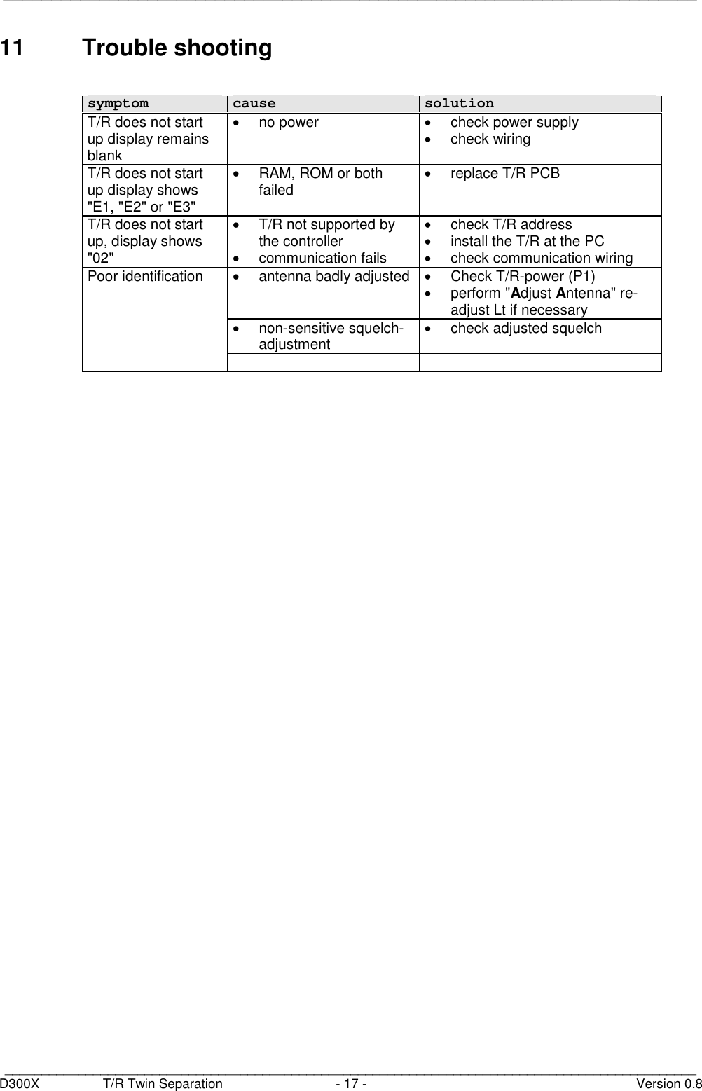
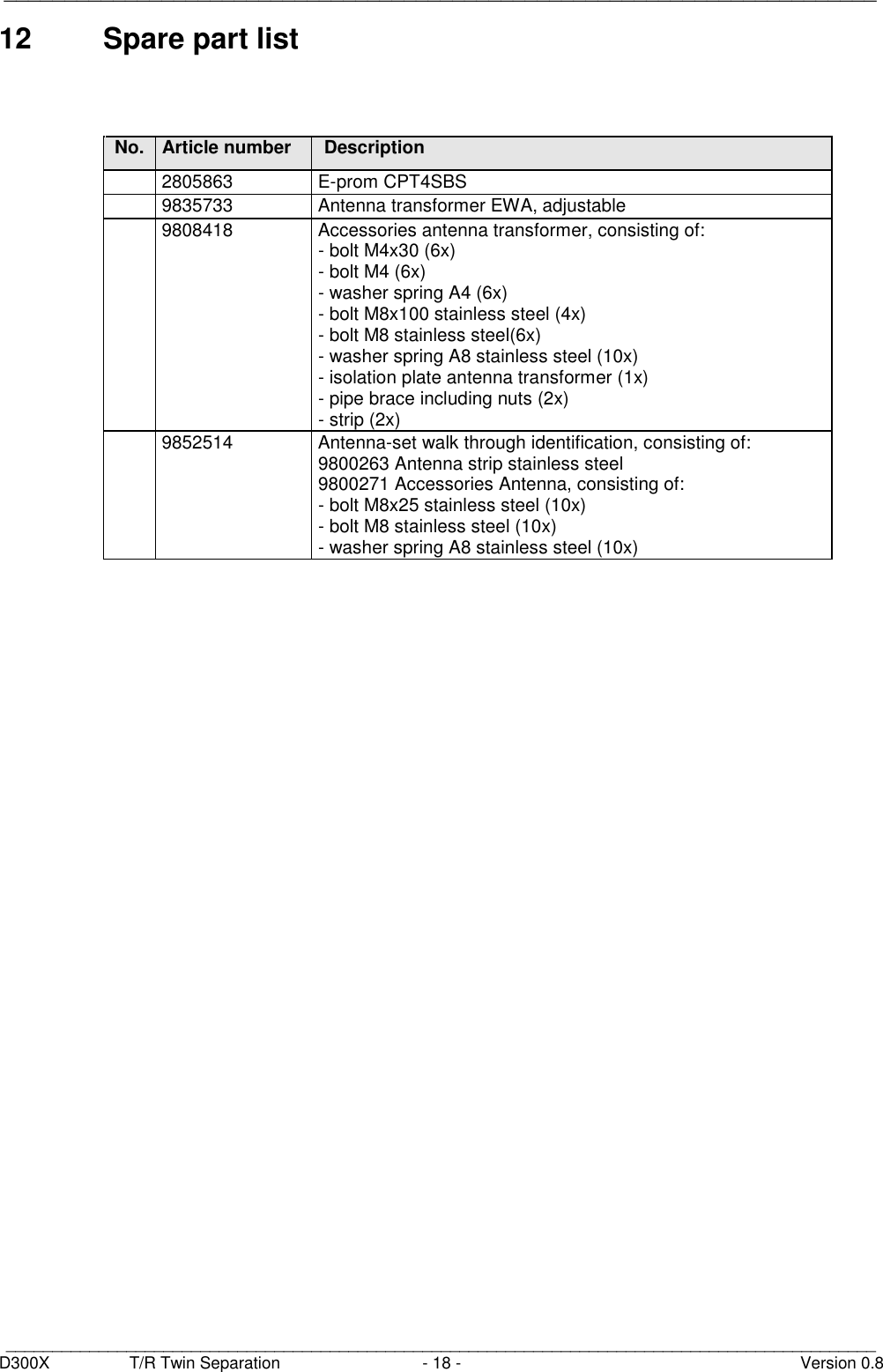
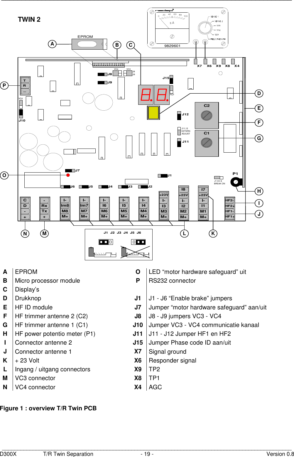
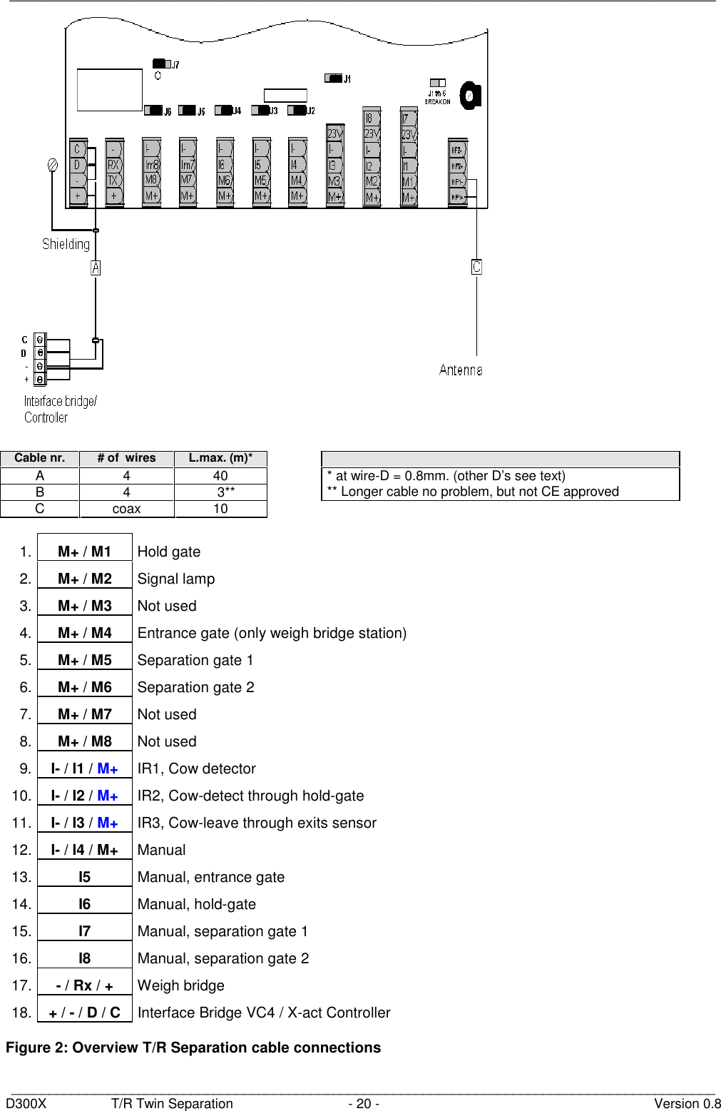
Nedap N V TF2 Inductive Card Reader User Manual 14 D300X 08 Manual CGD TF2

N. V. Nederlandsche Apparatenfabriek NEDAP Inductive Card Reader 14 D300X 08 Manual CGD TF2

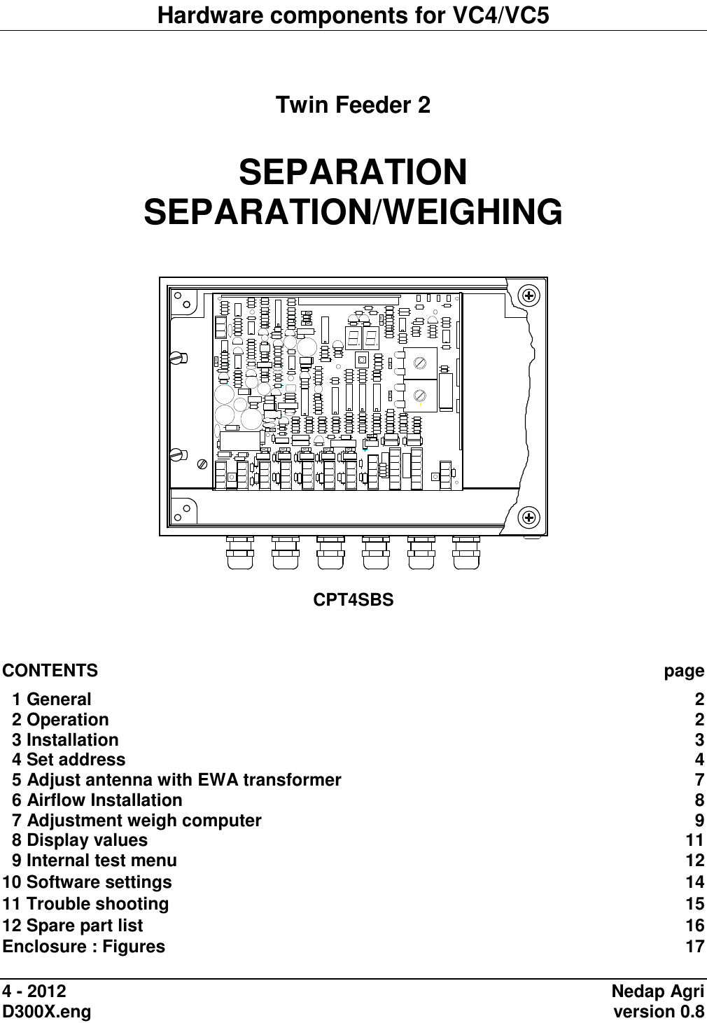
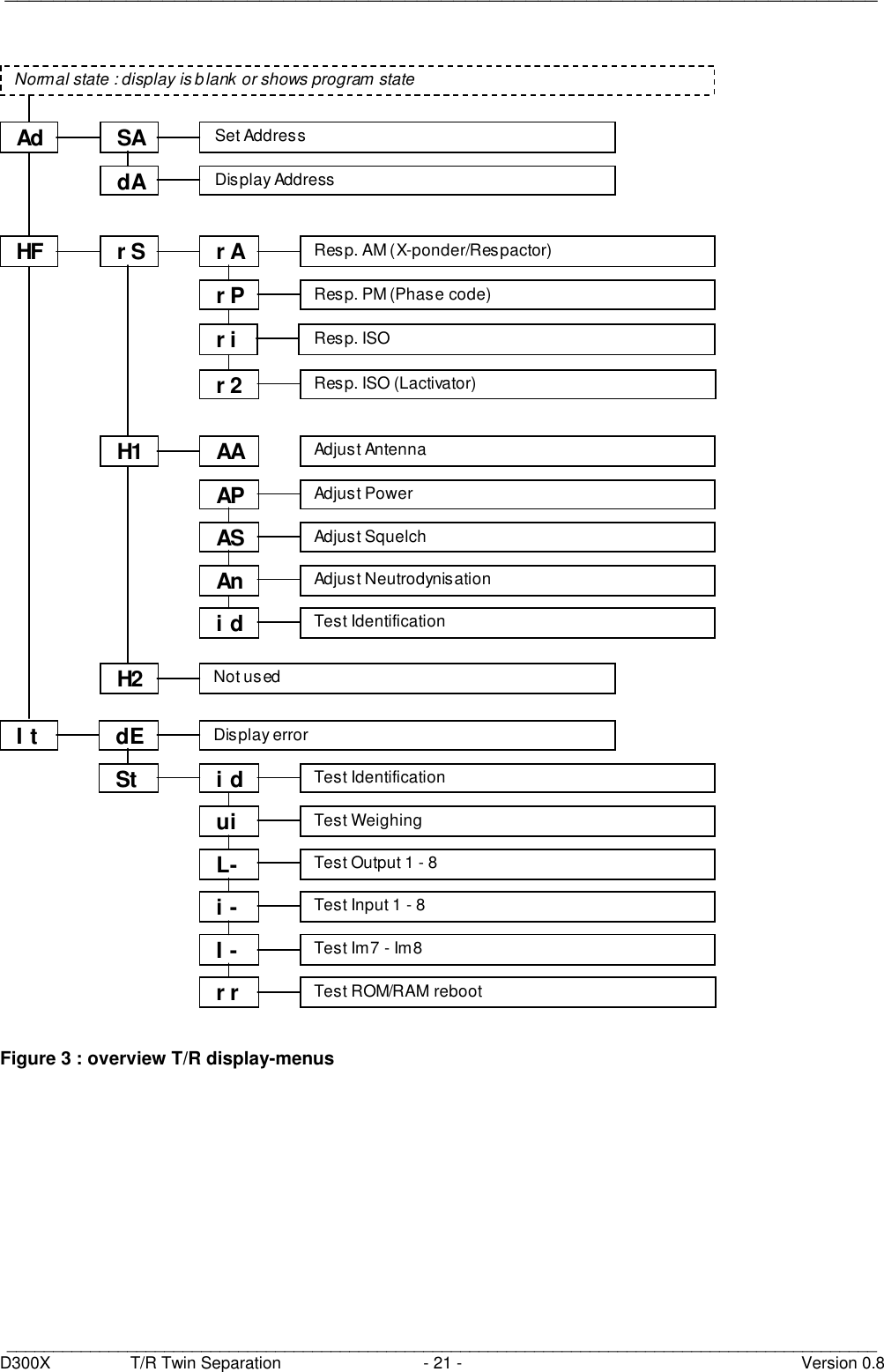
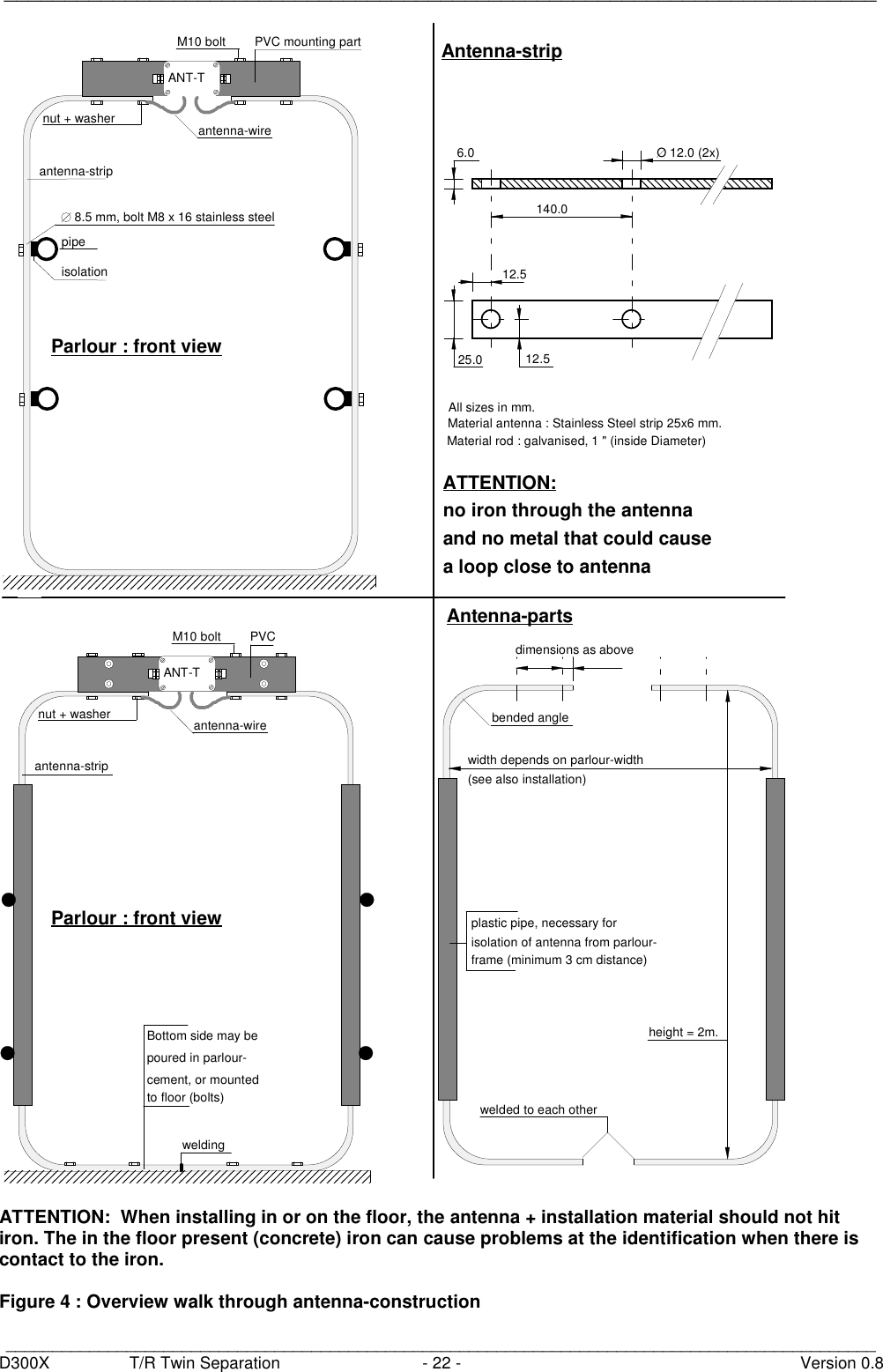
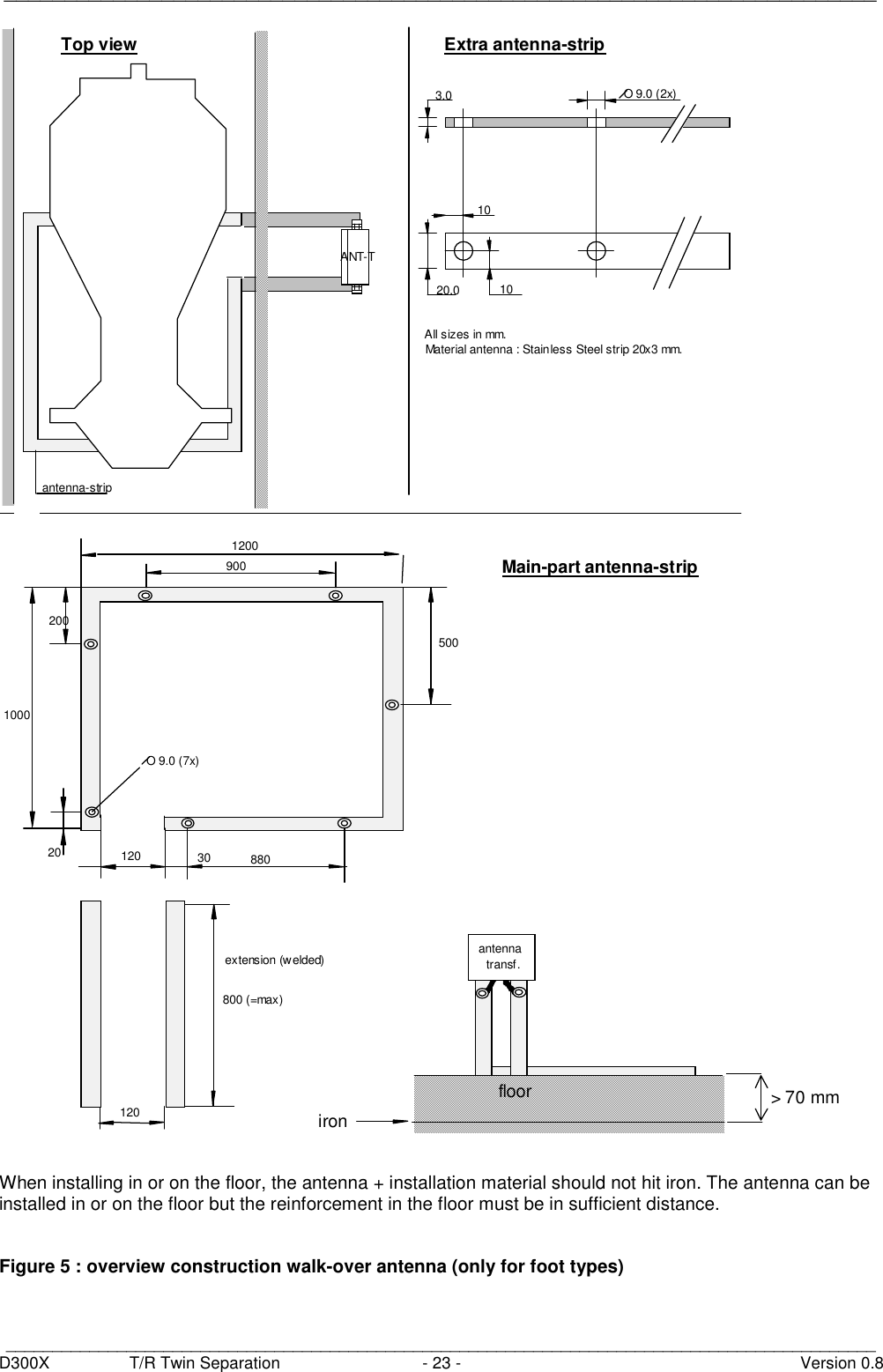
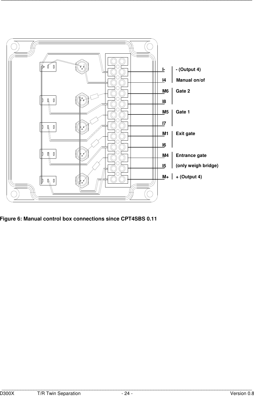
14_D300X.08 Manual CGD-TF2

Hardware components for VC4/VC5   Twin Feeder 2  SEPARATION SEPARATION/WEIGHING     CPT4SBS    CONTENTS  page   1 General  2   2 Operation  2   3 Installation  3   4 Set address  4   5 Adjust antenna with EWA transformer  7   6 Airflow Installation  8   7 Adjustment weigh computer  9   8 Display values  11   9 Internal test menu  12 10 Software settings  14 11 Trouble shooting  15 12 Spare part list  16 Enclosure : Figures  17  4 - 2012  Nedap Agri D300X.eng    version 0.8
 ________________________________________________________________________   ______________________________________________________________________________________________   D300X  T/R Twin Separation  - 1 -  Version 0.8 This documentation is part of the service manual VC4 CattleCode D300. Documentation version 0.2, first edition. Documentation version 0.3, weighing added Documentation version 0.4, Eprom version 0.13 added Documentation version 0.5, Welvaarts weighbridge added Documentation version 0.6, Eprom version 4.00 added Documentation version 0.7, Figure 2 : sensors connected to M+ instead of +23V Documentation version 0.8, FCC text added       PROM overview CPT4SBS     TwinFeeder      CPT4SBS 0.10  First field version    CPT4SBS 0.11  Weighing option added    CPT4SBS 0.12  Internal test menu : ROM/RAM test was not displayed     CPT4SBS 0.13  Identification : responder valid time shorter 1-2006    CPT4SBS 4.00  - Suitable for TF model 2 and 4 - 2 hour activity added (Lacitvator, VC5 only)        FCC ID: CGD-TF2   IC: 1444A-TF2  Compliance statements (Part 15.19) This device complies with Part 15 of the FCC Rules and to RSS210 of Industry Canada. Operation is subject to the following two conditions: (1) this device may not cause harmful interference, and (2) this device must accept any interference received, including interference that may cause undesired operation.  Cet appareil se conforme aux normes RSS210 exemptés de license du Industry Canada. L'opération est soumis aux deux conditions suivantes: (1) cet appareil ne doit causer aucune interférence, et (2) cet appareil doit accepter n'importe quelle interférence, y inclus interférence qui peut causer une opération non pas voulu de cet appareil.  Warning (Part 15.21) Changes or modifications not expressly approved by party responsible for compliance could void the user’s authority to operate the equipment. This in particular is applicable for the antenna which can be delivered with this System.
 ________________________________________________________________________   ______________________________________________________________________________________________   D300X  T/R Twin Separation  - 2 -  Version 0.8
 ________________________________________________________________________   ______________________________________________________________________________________________   D300X  T/R Twin Separation  - 3 -  Version 0.8 1  General       This document contains the description of the software CPT4SBS in combination with the T/R-Twin hardware for a separationbox.  The Transmitter/Receiver Separation Box Standard is used for identifying, separating or separating/weighing of cows. The separation system uses one antenna.  CPT4SBS   The name of the EPROM is CPT4SBS x.xx. Description of the code : Cattlecode Poiesz Twin VC4 Separation Box Standard.  2  Operation      Operation sequence •  Every cow is stopped at the hold-gate •  After identification of the responder the T/R sends a request for separation-data •  If weigh computer is connected, wait for weigh data •  When weigh data is received and separation data is received the separation gates are set, the hold gate will open •  After hold gate is open the twin is waiting for IR2 (only if responder is out of the antenna) •  As long as IR2 is activated the hold gate will not close •  When IR2 is free the hold gate will close •  When IR2 is free, IR3 is already activated •  Station is ready for the next cow as soon as IR3 is free       Operation sequence cow with no responder •  Cow is stopped at the hold-gate •  IR1 is activated, twin remains waiting for responder number •  After maximum ID time the cow will be sent to the default exit
 ________________________________________________________________________   ______________________________________________________________________________________________   D300X  T/R Twin Separation  - 4 -  Version 0.8 3  Installation      The Nedap guarantee-regulations are only valid when the T/R is mounted and installed as indicated in this chapter. The following is important :     •  operating temperatures -10ºC .... +40ºC •  storage temperatures -25ºC .... +70ºC •  tightness IP 65, cover and cables mounted correctly •  input voltage 28 VDC  +10% / - 20%, power supply at least 40 W (continuous) •  abs. max. voltage (+/-) 40 V DC, 35 V RMS, protected against reverse polarity   - never change a PROM when the power to the T/R is still switched on !  - shut off the power when service is needed for the station !      Antenna construction     The antenna must be installed around the station (see figure 5). When the HF-field is adjusted correctly, the cows inside the station must be identified easily when they are walking through the station.      Jumper settings     To install the T/R Twin correct, some jumper settings must be checked or changed. Jumper J7 must be set to the left (LED is ON) Jumpers J1 – J6 must be set to the right (brake off) Antenna jumpers must be set to the lowest position (external adjust)      Wiring the T/R     Figure 2 shows an overview of the T/R-Twin cable-connections.    Cable C = coax, in this case it is important the shielding is connected to HF-      Max. cable-lengths, wire-ø's and cable colours     The cable-overviews in the figures all     show Lmax. at wire-ø = 0.8 mm. cable  colour       C  white     The values for Lmax at ø=1.0 and ø=1.2 :  D  yellow     Lmax.(ø=1.0) = 1.5 x Lmax.(ø=0.8)  -  black     Lmax.(ø=1.2) = 2.0 x Lmax.(ø=0.8)  +  red      Shielding, grounding     In order to protect the VC-System for over-voltages, due to severe thunderstorms, cable A in figure 2 must be a shielded cable. The cable-shield however may not be used as a wire for current-supply. The cable-shield of cable A is as follows :     Transmitter / Receiver connected to ground-terminal     N.B.  All T/R electronics must be isolated from the parlour. This implicates that also the T/R bottom has to be isolated from the T/R ground-terminal.              Warnings    •  Due to guarantee-regulations, the entire T/R PCB (incl. metal plate) must be changed. •  For continued protection against fire, always replace with same type and rating of fuse.
 ________________________________________________________________________   ______________________________________________________________________________________________   D300X  T/R Twin Separation  - 5 -  Version 0.8 4  Set Address      For communication the Transmitter / Receiver needs an address. Then the computer knows where to send the information to. At the transmitter / receiver with help of the display and the push button the stations address is configured.          The two segment display and the yellow push-button must also be used for several adjustments of the Transmitter / receiver. A number of different codes will appear on the display when the push-button is pushed, these codes represent the so-called menus. Each menu on its turn is divided into a number of functions. By varying the pushing time of the push-button, you will get access to the different menus and/or functions. The first time you switch on the power of the T/R, the display will show "0-". The Transmitter / Receiver asks now for the first address. When an address is entered the display will blank out and the transmitter / receiver returns to the normal status.          The address setting concerns the following menus and procedures (see figure 3):    • Address menu - Set Address - display Address         N.B.  The address-range of all connected peripherals on the same controller channel is from 1-50.   Remember that the used peripheral-address has to be unique on this controller channel.      Changing addresses   When the display shows SA, the "Set Address procedure" is entered by pressing the button until the display blinks. The procedure is as follows :         set decimal-digit display scrolls from 0- through 5-    set unit-digit display scrolls from x0 through x9         •  to indicate that the "Set Address procedure" has been entered, the display will show "0-" •  by pressing the button short, the next decimal will be displayed ("1-","2-"...."5-") •  the displayed decimal is entered by pressing the button until the display blinks •  when the decimal has been entered, the display will show "x0" (where x = entered decimal), the unit-digit now can be entered •  by pressing the button short, the next unit will be displayed ("x1", "x2", .. , "x9") •  the displayed unit is entered by pressing the button until the display blinks         The following points should be noted    •  the "Set Address procedure" can be quit by pressing the button until the   display blanks. The entered digits then are not stored •  the T/R will restart when the address is changed     Show addresses   When the display shows dA, the "display Address procedure" is entered by pressing the button until the display blinks. The display then shows the T/R  address.
 ________________________________________________________________________   ______________________________________________________________________________________________   D300X  T/R Twin Separation  - 6 -  Version 0.8 5  Adjust antenna with EWA transformer    The antenna adjustment has to be done with help of the display, push button, P1 on the T/R and the antenna transformer settings. Below you find the HF-menu, see also figure 3.    Jumper settings on the transmitter / receiver When using an EWA antenna transformer jumpers J11 and J12 should be set to position B    HF menu  Responder Select Adjust Antenna  Adjust Power  Adjust Squelch Adjust Neutro Identification •  selection of responder type •  adjust antenna by means of tuning capacitor Ct •  adjust transmitter-power by means of potentio meter P1 •  adjust receiver-sensitivity (0,1,2,3) •  adjust neutrodynisation •  Test identification ⇒⇒⇒⇒ The antenna adjustment-procedure consists of several steps. It is essential that these steps are executed in the sequence as in the manual described.       Responder Select    During T/R start up there is auto detect of T/R type, 120kHz (for rA and rP) or 134.2 kHz (for ri and r2) rA = AM labels, X-ponder and Respactor (default) rP = PM labels, ear button and Phase code responders ri  = ISO responder types  (default) r2 = Nedap 2 hour activity meter (Lactivator) Select rS on the display and select the required type, press until display blinks to store the setting.       Adjust antenna   HF menu, select H1 for antenna 1 or H2 for antenna 2  ⇒⇒⇒⇒ The antenna adjustment-procedure consists of several steps. It is essential that these steps are executed in the sequence as described. First "AA", then "AP" and last "AS", described in step 1, 2, 3 and 4.     While tuning Lt  the following must be noted •  The tuning of Lt must be done with a non-metal screw-driver (e.g. plastic)  •  This tuning of Lt requires a short circuit of the "Antenna adjust input" on the T/R, see jumper settings. •  It is possible that the trimmer-coil must be turned so far out of the coil housing that the transformer box does not close anymore. In that case, turn the trimmer-coil completely in the coil housing. In this way the same adjustment can be achieved.
 ________________________________________________________________________   ______________________________________________________________________________________________   D300X  T/R Twin Separation  - 7 -  Version 0.8 Step 1  Jumper setting on Antenna-Transformer  •  measure the circumference of the antenna-loop •  set jumpers to combination as described in table on Antenna-Transformer PCB, note that the highest possible number should be chosen.   e.g. Antenna circumference = 6 meters. According to the table on the Antenna-Transformer PCB, 2 combinations are possible :           NR. Combination Antenna length    1  A0     B0  5.8 - 8.2 meters   2 A0      B2 4.2 – 6.6 meters  In this example, the jumpers should be set to combination 2. (2 is highest number and shortest length)   Step 2  Transformer-ratio on the Antenna-Transformer and Lt adjustment     The transformer-ratio determines the HF-current through the loop-antenna, which determines the power of the HF-field. In principle the highest transformation-ratio should be selected. This however can be limited by the fact that the antenna-circuit then can not be brought in resonance anymore (= highest value on the display).     13 2 9 neutroZ/O M (HF+/-)9 : 113 2 9 neutroZ/O M (HF+/-)11 : 113 2 9 neutroZ/O M (HF+/-)13 : 113 2 9 neutroZ/O M (HF+/-)15 : 1Figuur  :Transformatie-aansluitingenverhouding   The following has to be done  •  turn the trimmer coil (Lt) completely in the coil housing. •  connect HF-output of T/R (HF +/-) to input of ANT-T with the transformation-ratio according to the table below for rough adjustment.     Note : The length of the example is about 6 m      Length of Antenna   Transformer ratio      till 3,5 m  15 : 1     3,6  -  4,7 m  13 : 1   4,8  -  6,6 m 11 : 1     6,7 or larger    9 : 1     •  select AA (Adjust Antenna see figure 2) on the display, then push the button until the display starts to blink.  •  with P1 (figure 1) the displayed value must be set to 30 •  after adjusting P1, the value must be adjusted with Lt (figure 1) on the EWA transformer to a maximum value. Tune (with plastic screw driver) the trimmer Lt on the antenna transformer until the highest point has been found (is highest display value, this means when you are turning further in the same direction the display value must go down after the highest level has been found, if not select a different transformer ratio.)  •  connect HF-output to the next transformer-ratio 9 : 1, or 11 : 1 (do not change HF+ and HF-), try if a higher value on the display can be found by tuning Lt.  •  connect HF-output to the highest transformation-ratio (with the highest value on the display) where it is still possible to find the highest point, this is the right adjustment. •  When the right transformation ratio has been found Lt must be tuned to the maximum  A2100B
 ________________________________________________________________________   ______________________________________________________________________________________________   D300X  T/R Twin Separation  - 8 -  Version 0.8 step 3 Adjust power   After correct processing the antenna adjustment procedure, step 1 and 2 are done and Lt is adjusted (highest value is on the display now ),  P1 must be adjusted with help of AP.  When the display shows AP, the "Adjust Power procedure" is entered by pressing the button until the display blinks. The display now shows the percentage of the maximum transmitting-power of the T/R. The T/R is equipped with a power-limitter. When the transmitted HF-power exceeds a certain level, the HF-current will be limited automatically. To indicate this, the display will blink, after this point power-increase (P1) is not desirable. The tuning-procedure is as follows :  set power-level  tune P1 maximal until just before the point where the display starts to blink  You can continue by pressing the button short   step 4 Adjust squelch procedure  The adjusted squelch determines the sensitivity of the receiver in the T/R. In case e.g. calves outside the station are identified, the transmitted power can be reduced ("Adjust Power procedure") or the receiver-sensitivity can be reduced by means of the squelch-adjustment.     Normally squelch does not have to be adjusted (default is automatically set  When the display shows AS, the "Adjust Squelch procedure" is entered by pressing the button until the display blinks. The display now shows the actual sensitivity of the receiver, a value from "-0" (most sensitive, i.e. default setting) until "-3" (least sensitive). By shortly pressing the button, the desired squelch can be adjusted. The setting can be entered by pressing the button until the display blinks.   Advised and Default Squelch settings CPT4SBS   Twin Feeder Model 1  Squelch = 0   Twin Feeder Model 2   AM CODE  Squelch = -2   Twin Feeder Model 2   PM CODE  Squelch = -1      Note :  AS can be used to reduce the HF-field if animals are identified outside the station, check if the identification is still sufficient
 ________________________________________________________________________   ______________________________________________________________________________________________   D300X  T/R Twin Separation  - 9 -  Version 0.8 6  Airflow Installation    •  The main pressure has to be 85 P.S.I. (6 bar) With this pressure the main cylinders are controlled. The speed of the out going cylinders is controlled by the regulator at the point R and the speed in going cylinders by regulator at point S on the control plate.   PABRSM+ MxAIR
 ________________________________________________________________________   ______________________________________________________________________________________________   D300X  T/R Twin Separation  - 10 -  Version 0.8  7  Adjustment weigh computer     This weigh computer can automatically weigh animals. The weight is sent to the Twin T/R and then transferred to the VC computer. The weigh computer has 3 modes, namely: •  weighing mode •  calibration mode •  setting mode     ChargeGROSSNETTOTALkg GROSS/NETTARE/ZEROTOTALPRINTON/OFFTYPE W-2000-Rx+Pen 2Pen 1Pen 3not usedTxTWIN Transmitter / ReceiverWeigh platformHorizontal floor levelWeigh computerFigure 3 :Weigh computerconnections   Weighing mode When the weigh computer is switched on, the computer will automatically go over to the weighing mode. The computer is now ready for normal use.   Calibration mode The calibration mode is selected to adapt the computer to the weighing platform or to calibrate the computer. This is done as follows: Switch the computer on and hold down the "TOTAL" key. After a standard text message, the computer gives a bleep signal. You will now see the word "POS --" on the screen. Now release the "TOTAL" key and press any key you like.  Set the computer to gross by pressing the "GROSS/NETT" key. The scale zero can now be set. To do this, open up the weigh computer. Two potentio meters which have to be calibrated are located on the PCB in the housing cover. The left hand potentio meter is used to set the zero weight and the right hand potentio meter is used to set the correct weight. Use the left hand potentio meter, set the computer to zero. If you want to reduce the value, turn clockwise and if you want to increase it, turn in the opposite direction. Now place a known weight on the scale, preferably about the same weight as the animals to be weighed. Using the right hand potentio meter, set the computer to the right weight. Remember, clockwise for higher values, and anti-clock wise for lower values. When you want value's in pounds (lb) you have to turn the weight to the lb value. Remove the calibration weight from the scale and check the zero position on the computer. Correct if necessary. The computer is now calibrated. It is possible to weigh normally again by simply switching the computer off and on again.
 ________________________________________________________________________   ______________________________________________________________________________________________   D300X  T/R Twin Separation  - 11 -  Version 0.8    Setting mode The behaviour of the weighing computer may be influenced by three parameters. To change these parameters, the computer has to be in the setting mode. This is done by switching the computer on and holding down the "TOTAL" and the "PRINT" key at the same time. When the screen message has disappeared, the computer gives a bleep signal and you will now see "P-" appear on the screen. Now release the two keys and press the "GROSS/NETT" key once. The computer now displays "PI XX", when XX represents the value of parameter 1. Therefore, you do not actually see "PI XX", on the screen, but "PI 25", for example. The damping of the scales is set with parameter1. This value can be set from 0 - 63, inclusive, when 0 indicates the minimum damping. This adjustment is made with the "TOTAL" key increases the value of the parameters, the "PRINT" key reduces it. (Best value of P1 = 10)  After setting the damping, you can switch over to the second parameter, P2. This is done by pressing the "GROSS/NETT" key. Parameter 2 indicates the stable factor. The computer only transmits data to the VC computer if the weight is "stable". "P2" sets exactly how stable the weight must be. Possible values for "P2" are 1 - 99. At 1 the weight must be very stable and when at a value of 99 practically everything is regarded as stable. (Best value of P2 = 15)  The third parameter P3 can be set by pressing the  "GROSS/NETT" key once more. The peak value of "P3" can be set between 1 - 5 inclusive. "P3" is a multiplying factor. Normally "P3" is set at 1. If the "P3" is set to 5, the weight is multiplied by 5. This weight is then displayed and may also be transmitted to the VC computer. After setting "P1", "P2" and "P3", inclusive, the "GROSS/NETT" key has to e set once more. The computer is now ready for use and does not have to be switched off and on. The values "P1", "P2" and "P3", inclusive are stored even when the computer is switched off. If the computer is switched to calibration mode, parameter "P3" is set to 1 automatically. This is still the case after leaving the calibration mode. Therefore, if another multiplying factor is needed, this has to be set again after leaving the calibration mode. (Best value of P3 = 1).     Summary   normal start    weighing mode   switching on with "TOTAL" key left hand potention meter: zero setting right hand side potention meter: weight setting calibration mode   switching on with "TOTAL" and "PRINT" key P1  damping factor    0-63 P2  stability factor    1-99   P3  multiplying factor  1-5 setting mode (i.e. 10) (i.e. 15) (i.e.   1)
 ________________________________________________________________________   ______________________________________________________________________________________________   D300X  T/R Twin Separation  - 12 -  Version 0.8  8  Display values       During operation, the program steps through different program-states which are monitored on the display. This gives information about the state of the T/R and therefore can be used as an extra service tool.         Start process : status 0-5         status description of the status     00  processor-initialisation, opening network     01  wait for valid address, "SA"-menu is started automatically     02  No communication with process computer. Request for total peripheral number. At installation the controller asks here for peripheral information     03  request for external data     04  T/R under test     05  start-up process finished, task is killed         Display during normal operation         status Description of the status    •  left & right display  "--" when the T/R tries to identify a responder.    •  decimal point left display  Cow-responder currently identified    •  decimal point right display  HF1 field on            10  Initiate station     11  Wait for responder number     12  Sensor at antenna (IR1) occupied, no responder ID     13  Check gate positions (waiting for weigh data)     14  Wait for station to be free     15  Wait for hold gate sensor (IR2) to be active     16  Wait for hold gate sensor (IR2) to be free     17  Manual Control     21  Wait for separation sensor (IR3) to be active     22  Wait for cow-id (second cow identified, first cow has not left yet)     23  Check gate position (second cow identified, first cow has not left yet)     24  Wait for station to be free (second cow identified, first cow has not left yet)     25  Wait for separation sensor (IR3) to be active Responder still identified in antenna when IR2 became free     26  Wait for separation sensor (IR3) to be free      The display returns blank when the button is not touched for 30 minutes.
 ________________________________________________________________________   ______________________________________________________________________________________________   D300X  T/R Twin Separation  - 13 -  Version 0.8 9  Internal test menu      The different functions of the transmitter / receiver can be tested by means of the push-button. A special program is build into the prom of the T/R. On the display this option is called “It”, which stands for “Internal test” The Internal test menu is a powerful service tool in case of system-service. The T/R stores registered errors which can be displayed on demand of the trouble-shooter. Also the T/Ran execute a complete self test on demand, the test results also are displayed.       Internal test menu − display Error procedure − Self test menu :     Display error procedure   The detected errors are stored by the T/R itself and can be monitored on the display. When the display shows dE, the “display Error procedure” is entered by pressing the button until the display blinks. Two types of messages can be displayed by the T/R :  •  error-messages   (E1) •  warning-messages  (E2, not used yet)  The procedure shows all registered errors on the display, one after the other, proceeded by the message-type. First all error-messages will be shown, then all warning-messages.    Error Description how to handle   - - no errors     01  Tare too high for more than 20 seconds  Clear the weighing platform or reset the weighing unit   09  No HF1- current detected  •  Check antenna wiring •  Check HF-field (test responder) •  Replace T/R T-PCB   10  Antenna error  See error 09   11  RAM ERROR: • data written does not match data  Replace T/R T-PCB   12  ROM ERROR: • calculated checksum does not match checksum of EPROM Replace T/R T-PCB         Self test menu When the display shows St, the “Self test menu” is entered by pressing the button until the display blinks. By shortly pressing the button, the T/R self tests can be selected. The selected test is executed by pressing the button until the display blinks.      Test output 1 – 8 When the displays shows LX, the “test output procedure” is executed by pressing the button until the display blinks. The device connected to the output will now be switched ON
 ________________________________________________________________________   ______________________________________________________________________________________________   D300X  T/R Twin Separation  - 14 -  Version 0.8    Test input 1- 8 When the displays shows iX, the “test input procedure” is executed by pressing the button until the display blinks. 01 = contact open 00 = contact closed     Test input Im7 –8 When the displays shows IX, the “test input procedure” is executed by pressing the button until the display blinks. 01 = contact open 00 = contact closed     Test identification procedure When the displays shows id, the "test identification procedure" is executed by pressing the button until the display blinks. The HF-field now continuously will be on. The ID-status is displayed as follows (switching HF1 / HF2):  - -   = no responder identified xx  = responder identified ( xx = last two digits of responder number)      Test weighing unit    Weighing status is displayed, when weighing bridge connected.     - -   = no weighing data read    xx  = absolute weighing result (xx = last two digits of weighing data)     Test ROM / RAM When the display shows rr, the "test ROM / RAM procedure" is executed by pressing the button until the display blinks. The T/R now will restart, during which the memory-tests are executed. The table underneath shows an overview of the return values of these tests.    E1 RAM error   E2 ROM error   E3 RAM and ROM error
 ________________________________________________________________________   ______________________________________________________________________________________________   D300X  T/R Twin Separation  - 15 -  Version 0.8 10  PC-software settings VC4    In the installation program the following must be keyed in at the screen separation:     System >> Service >> Installation >> Installation         Recommended settings for CPT4SBS 0.12/0.13 and X-Act version 2.11/3.01    S W S = separation box    W = weighing / separation box  1. Weighing enable 0  1  Weighing enable / disable  2. Max ID Time  10  60  If the animal is not identified during this time, the animal will be send to the default exit (sec.)  3. Not used 0  0    4. Default exit 5  5  Default exit   5 = no exits selected 1 = exit 1 2 = exit 2  5. Scale type 0  1  1 = standard weigh computer  6. Max. weigh var. 0  50  Max. variation between two weighings (kg)  7. Max. tare weight 0  30  Max. tare weight (kg)  8. Min. weight 0  50  Min. accepted weight (kg)  9. Max. weight 0  1000 Max. accepted weight (kg)  10. Gate switch time 5  5  Wait time between gate actions (0.1sec.)  11. Sensor free y/n 1  1  1= Station is free if sensor is NOT made 0= Station is free if sensor is made  12. Return to default 1  1  1= Always return back to default gate settings  0= Set gate when new cow is identified  13. Not used 0  0    14. Max. track time 60  60  Max. time an animal can occupy the station (sec.)
 ________________________________________________________________________   ______________________________________________________________________________________________   D300X  T/R Twin Separation  - 16 -  Version 0.8  11  PC-software settings VC5     First create locations. Select tab sheet locations at the left. Select the farm icon in the tree and press button “NEW”. After saving the new location will appear in the tree.        When ready creating locations, select button “service” and start scanning devices. After scanning the devices connect the separation locations to the exits.
 ________________________________________________________________________   ______________________________________________________________________________________________   D300X  T/R Twin Separation  - 17 -  Version 0.8  11  Trouble shooting    symptom  cause  solution   T/R does not start up display remains blank •  no power •  check power supply •  check wiring  T/R does not start up display shows "E1, "E2" or "E3" •  RAM, ROM or both failed •  replace T/R PCB  T/R does not start up, display shows "02" •  T/R not supported by the controller •  communication fails •  check T/R address •  install the T/R at the PC •  check communication wiring  Poor identification •  antenna badly adjusted •  Check T/R-power (P1) •  perform "Adjust Antenna" re-adjust Lt if necessary   •  non-sensitive squelch- adjustment •  check adjusted squelch
 ________________________________________________________________________   ______________________________________________________________________________________________   D300X  T/R Twin Separation  - 18 -  Version 0.8 12  Spare part list      No. Article number Description    2805863  E-prom CPT4SBS    9835733  Antenna transformer EWA, adjustable    9808418  Accessories antenna transformer, consisting of: - bolt M4x30 (6x) - bolt M4 (6x) - washer spring A4 (6x) - bolt M8x100 stainless steel (4x) - bolt M8 stainless steel(6x) - washer spring A8 stainless steel (10x) - isolation plate antenna transformer (1x) - pipe brace including nuts (2x) - strip (2x)    9852514  Antenna-set walk through identification, consisting of: 9800263 Antenna strip stainless steel 9800271 Accessories Antenna, consisting of: - bolt M8x25 stainless steel (10x) - bolt M8 stainless steel (10x) - washer spring A8 stainless steel (10x)
 ________________________________________________________________________   ______________________________________________________________________________________________   D300X  T/R Twin Separation  - 19 -  Version 0.8 CADBPOEGFJ1  J2  J3  J4  J5  J6H9829601IJNM L KTWIN 2M+ M+I- I-+23V +23V +23VM3 M1M+I-M6I6 I3 I1I7I8HF2+HF2-_TRJ1J2J3J4J5J6J7J8J9J11J12J15C2C1J10X4X9X6 X8X7VC4 VC3J9J8PCFJ11,12EXTERNADJUSTJ1 t/m 6BREAK ONVC4HF1+HF1-+CD-+-TxRxM+I-M8Im8M+I-M7Im7M+I-M5I5M+I-M4I4M+I-M2I2P1 EPROM  A EPROM O LED “motor hardware safeguard” uit B  Micro processor module  P  RS232 connector C  Display’s    D  Drukknop  J1  J1 - J6 “Enable brake” jumpers E  HF ID module  J7  Jumper “motor hardware safeguard” aan/uit F  HF trimmer antenne 2 (C2)  J8  J8 - J9 jumpers VC3 - VC4 G  HF trimmer antenne 1 (C1)  J10  Jumper VC3 - VC4 communicatie kanaal H  HF power potentio meter (P1)  J11  J11 - J12 Jumper HF1 en HF2 I  Connector antenne 2  J15  Jumper Phase code ID aan/uit J  Connector antenne 1  X7  Signal ground K  + 23 Volt    X6  Responder signal L  Ingang / uitgang connectors  X9  TP2 M  VC3 connector  X8  TP1 N  VC4 connector  X4  AGC  Figure 1 : overview T/R Twin PCB
 ________________________________________________________________________   ______________________________________________________________________________________________   D300X  T/R Twin Separation  - 20 -  Version 0.8   Cable nr. # of  wires L.max. (m)*   A  4  40    * at wire-D = 0.8mm. (other D’s see text) ** Longer cable no problem, but not CE approved B  4     3**   C  coax  10              1. M+ / M1  Hold gate 2. M+ / M2  Signal lamp 3. M+ / M3  Not used 4. M+ / M4  Entrance gate (only weigh bridge station) 5. M+ / M5  Separation gate 1 6. M+ / M6  Separation gate 2 7. M+ / M7  Not used 8. M+ / M8  Not used 9. I- / I1 / M+ IR1, Cow detector 10. I- / I2 / M+ IR2, Cow-detect through hold-gate 11. I- / I3 / M+ IR3, Cow-leave through exits sensor 12. I- / I4 / M+  Manual 13. I5  Manual, entrance gate 14. I6  Manual, hold-gate 15. I7  Manual, separation gate 1 16. I8  Manual, separation gate 2 17. - / Rx / +  Weigh bridge  18. + / - / D / C  Interface Bridge VC4 / X-act Controller  Figure 2: Overview T/R Separation cable connections
 ________________________________________________________________________   ______________________________________________________________________________________________   D300X  T/R Twin Separation  - 21 -  Version 0.8   Set Address  Display Address  Normal state : display is blank or shows program state  Resp. AM (X-ponder/Respactor)  Adjust Power  Adjust Squelch  Test Weighing  Test Output 1 - 8  Test Input 1 - 8  Test Im7 - Im8  Test ROM/RAM reboot   Display error Test Identification  Ad  SA  dA  HF  r S  r A  Resp. PM (Phase code)  r P  AP  AS  Test Identification  i d  ui  L-   i -   I -   r r   I t   dE  i d  St   Adjust Antenna  H1  AA  Adjust Neutrodynisation  An  Not used  H2 Resp. ISO  r i   Resp. ISO (Lactivator)  r 2    Figure 3 : overview T/R display-menus
 ________________________________________________________________________   ______________________________________________________________________________________________   D300X  T/R Twin Separation  - 22 -  Version 0.8 140.0O 12.0 (2x)6.025.012.512.5Antenna-stripAntenna-partsdimensions as aboveAll sizes in mm.Material antenna : Stainless Steel strip 25x6 mm.width depends on parlour-width(see also installation)welded to each otherheight = 2m.plastic pipe, necessary for isolation of antenna from parlour-frame (minimum 3 cm distance)bended angleMaterial rod : galvanised, 1 " (inside Diameter)ATTENTION:no iron through the antennaand no metal that could causea loop close to antennaANT-TM10 bolt PVCnut + washer antenna-wireweldingBottom side may bepoured in parlour-cement, or mountedto floor (bolts)antenna-stripANT-TM10 bolt PVC mounting partnut + washer antenna-wire antenna-strippipeisolation 8.5 mm, bolt M8 x 16 stainless steelParlour : front viewParlour : front view  ATTENTION:  When installing in or on the floor, the antenna + installation material should not hit iron. The in the floor present (concrete) iron can cause problems at the identification when there is contact to the iron.  Figure 4 : Overview walk through antenna-construction
 ________________________________________________________________________   ______________________________________________________________________________________________   D300X  T/R Twin Separation  - 23 -  Version 0.8 ANT-T antenna-strip O 9.0 (2x) 3.0 20.0 10 10 Extra antenna-strip Top view All sizes in mm. Material antenna : Stainless Steel strip 20x3 mm. 500 900 1200 1000 20 120 880 30 200 O 9.0 (7x) Main-part antenna-strip 800 (=max) extension (welded) 120  antenna transf. > 70 mm floor iron   When installing in or on the floor, the antenna + installation material should not hit iron. The antenna can be installed in or on the floor but the reinforcement in the floor must be in sufficient distance.   Figure 5 : overview construction walk-over antenna (only for foot types)
 ________________________________________________________________________   ______________________________________________________________________________________________   D300X  T/R Twin Separation  - 24 -  Version 0.8     I7I8I4M4M1M5M+I5M6I6I-Manual on/ofEntrance gateExit gateGate 1+ (Output 4)Gate 2- (Output 4)(only weigh bridge)  Figure 6: Manual control box connections since CPT4SBS 0.11
 ________________________________________________________________________   ______________________________________________________________________________________________   D300X  T/R Twin Separation  - 25 -  Version 0.8 1000 mm 800 mm 300 mm 600 mm 100 mm 1200 mm  HF2 IR1 IR2 IR3  IR3   Figure 5: overview IR and antenna positions (2 IR sensors before separation door)   1000 mm 800 mm 300 mm 600 mm 100 mm 1200 mm  HF2 IR1 IR2 IR3  IR3 IR3   Note 1: Before the cow leaves IR2, the cow must be out the antenna field Note 2: Before the cow comes into IR3, the cow must be out of the antenna field  Max width of the box 80 cm, In case of small cows it is better to make it as small as possible   Figure 7: overview IR and antenna positions (3 IR sensors at separation door)
 ________________________________________________________________________   ______________________________________________________________________________________________   D300X  T/R Twin Separation  - 26 -  Version 0.8 IR3 IR2 IR3 600 mm 100 mm 1200 mm  HF1 IR1 100 mm 1200 mm  FRONT LEG ID    IR3 IR2 IR3 600 mm 100 mm 1200 mm  HF1 IR1 1300-1700 mm 1200 mm  BACK LEG ID (antenna position depending on cow length)  Figure 8 : overview dimensions separation box with foot identification
 ________________________________________________________________________   ______________________________________________________________________________________________   D300X  T/R Twin Separation  - 27 -  Version 0.8 IR1 IR3 IR2 IR3 1000 mm 800 mm 300 mm 600 mm 100 mm 1200 mm  HF1   Figure 9 : overview dimensions separation box  with identification on the side (ear button identification)

Navigation menu