Nedap N V TRANSED 2.4 GHz Microwave ID System User Manual Revision 2
N. V. Nederlandsche Apparatenfabriek NEDAP 2.4 GHz Microwave ID System Users Manual Revision 2
UserManual.wiki
>
Nedap N V
>
TRANSED User Manual
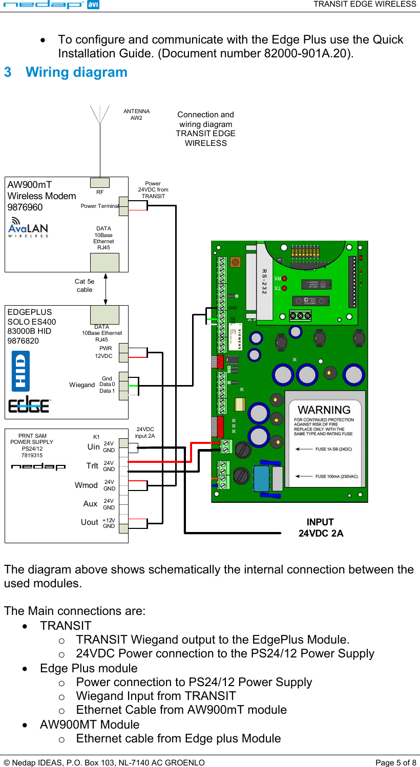
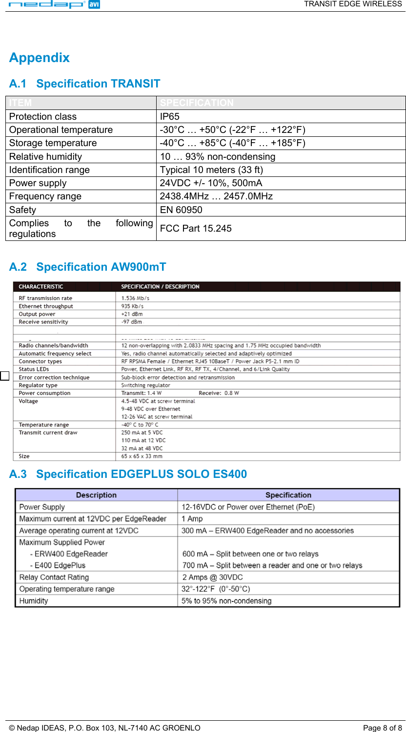
Users Manual Revision 2
Navigation menu
Upload a User Manual
Namespaces
Wiki Guide
HTML
PDF
Info
Views
User Manual
Discussion / Help
Navigation