Nedap N V TRANSITENTRY Microwave/Inductive Proximity Reader User Manual TRANSIT Entry
N. V. Nederlandsche Apparatenfabriek NEDAP Microwave/Inductive Proximity Reader TRANSIT Entry
UserManual.wiki
>
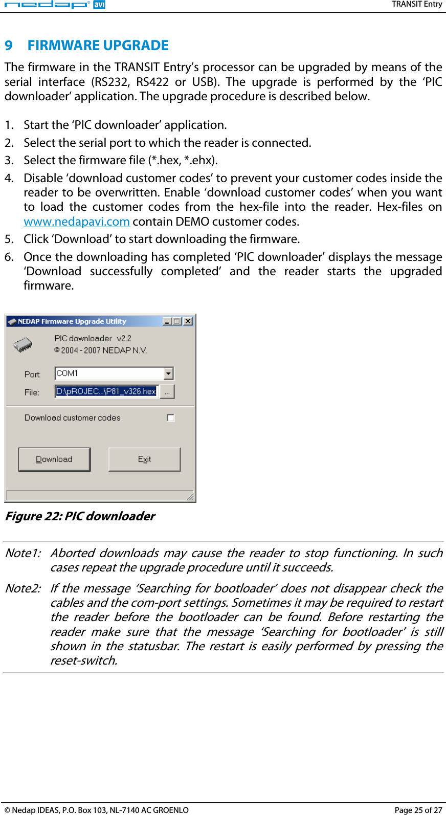
Nedap N V
>
TRANSITENTRY User Manual
User Manual
Navigation menu
Upload a User Manual
Namespaces
Wiki Guide
HTML
PDF
Info
Views
User Manual
Discussion / Help
Navigation