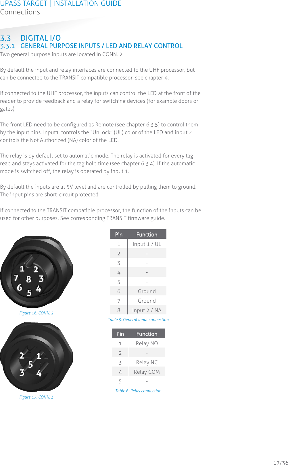
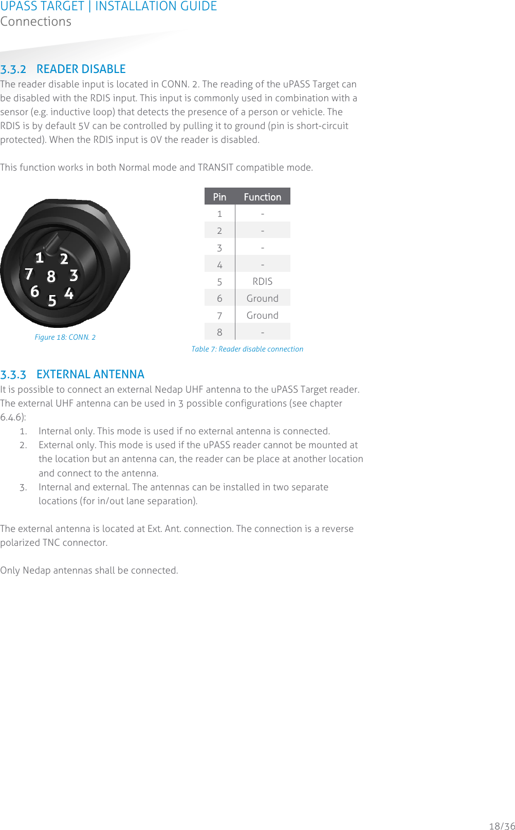
Nedap N V UPASSTAR UHF RFID reader User Manual uPass Target installation guide
N. V. Nederlandsche Apparatenfabriek NEDAP UHF RFID reader uPass Target installation guide
UserManual.wiki
>
Nedap N V
>
UPASSTAR User Manual
TempConfidential_14r01_Install manual T5481163-45.01-1.04 CGDUPASSTAR
Navigation menu
Upload a User Manual
Namespaces
Wiki Guide
HTML
PDF
Info
Views
User Manual
Discussion / Help
Navigation
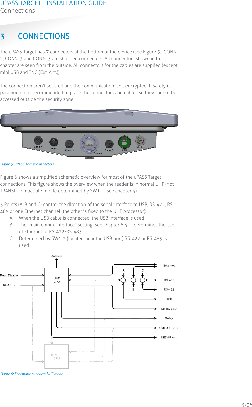
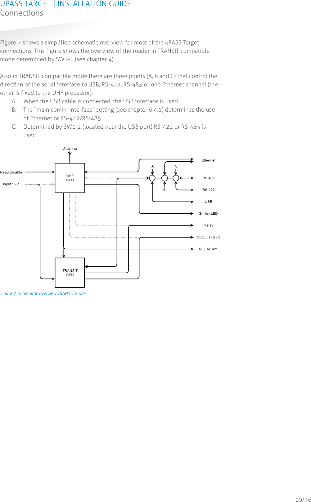
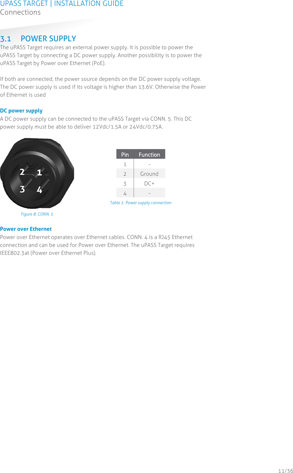
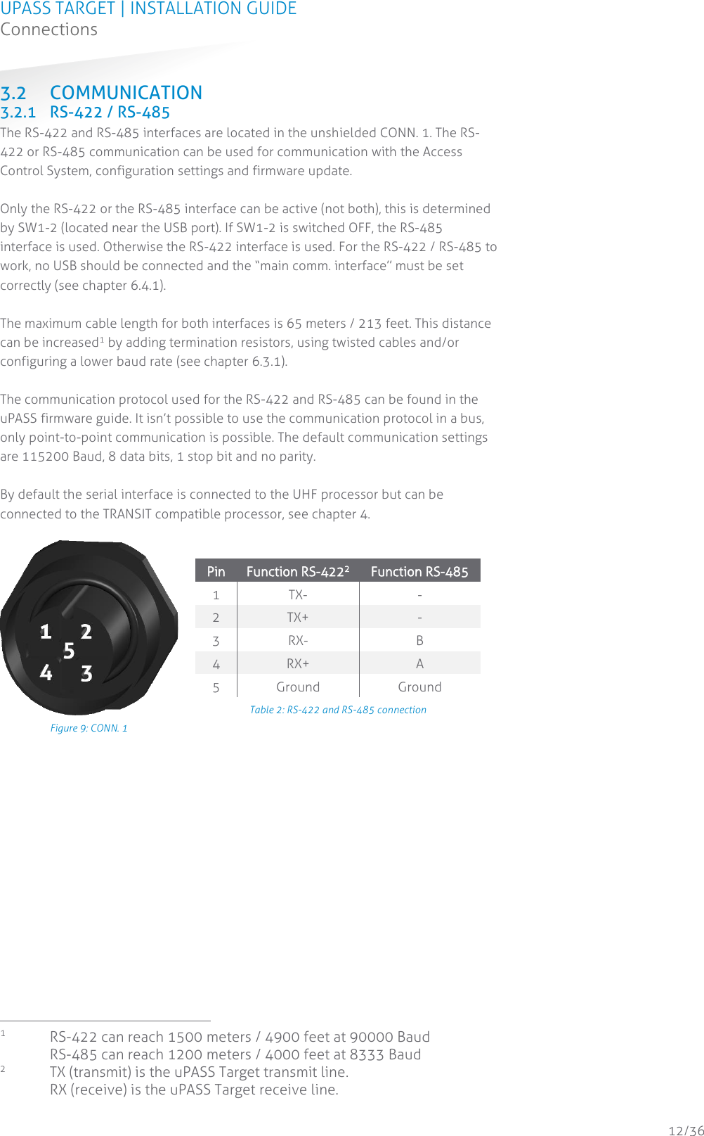
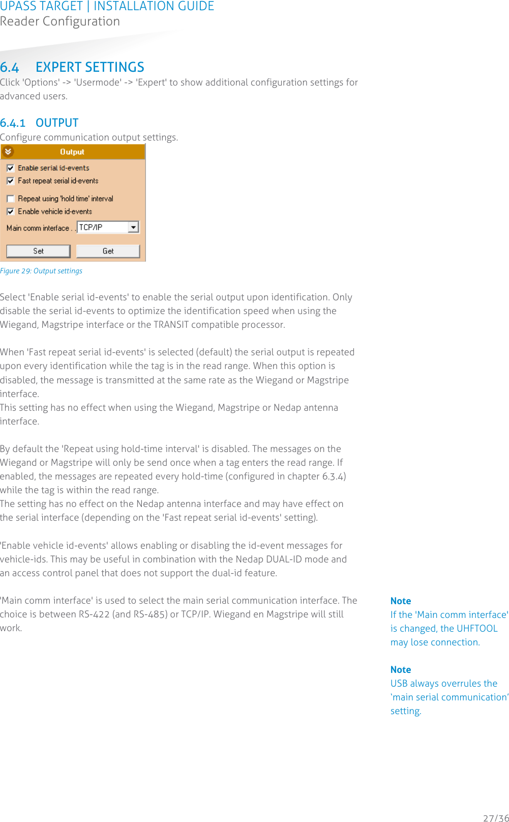
![UPASS TARGET | INSTALLATION GUIDE Reader Configuration 28/36 6.4.2 OUTPUT MESSAGE FORMAT Configure output message format. Figure 30: Output message format The output message format is configurable: [<PREF>] [<80 AC PH RSSI>] [<EL>] [<EPC>] [<DL>] [<DATA>] [<SUFF>] CR LF 6.4.3 EXTRA OUTPUT Optionally enable Wiegand or Magstripe output for tags that are not programmed by Nedap in a Wiegand, Magstripe or Nedap-XS format. See uPASS Wiegand output Application Note for more information. 6.4.4 FREQUENCY These settings show the reader's operating frequency region. Select a frequency channel (within the available frequency band) for systems that do not require frequency hopping. With 'Power on' the reader can be enabled or disabled. Figure 31: Frequency Note When the output message format is changed, identified tags may no longer be shown in the UHFTOOL.](https://usermanual.wiki/Nedap-N-V/UPASSTAR/User-Guide-2917243-Page-28.png)