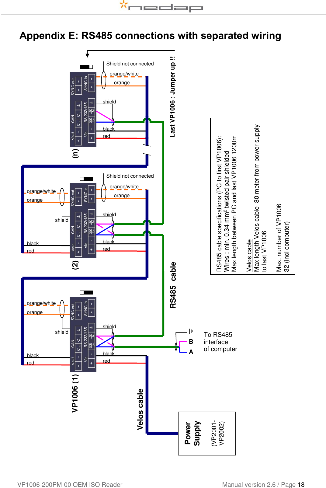
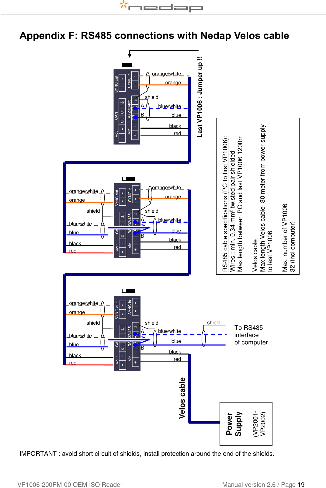
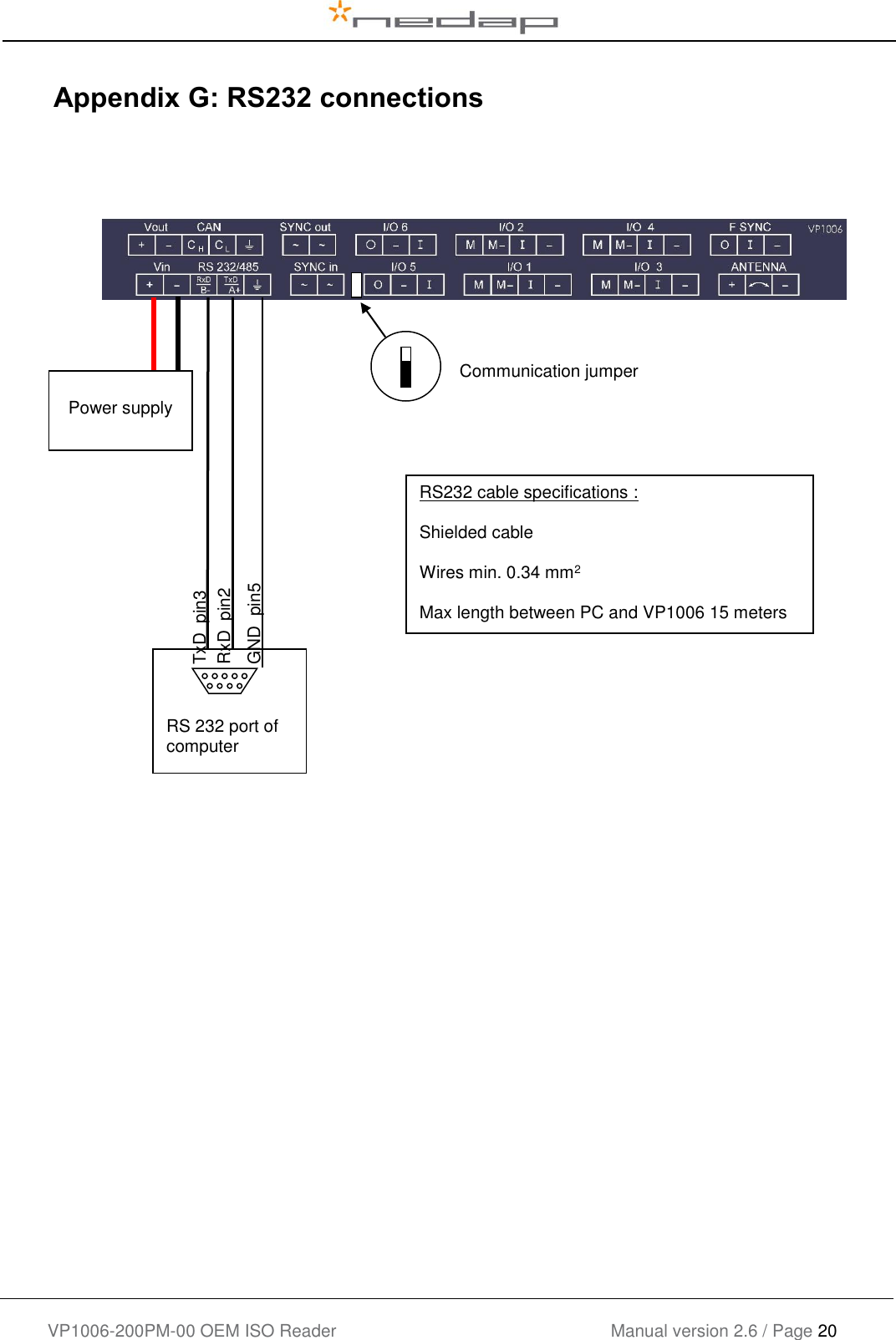
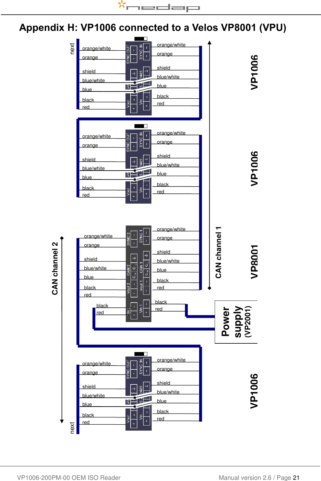
Nedap N V VELOS2 134 kHz Inductive proximity tag reader User Manual VP1006
N. V. Nederlandsche Apparatenfabriek NEDAP 134 kHz Inductive proximity tag reader VP1006
UserManual.wiki
>
Nedap N V
>
VELOS2 User Manual
>
Manual
Contents
1.
users manual
2.
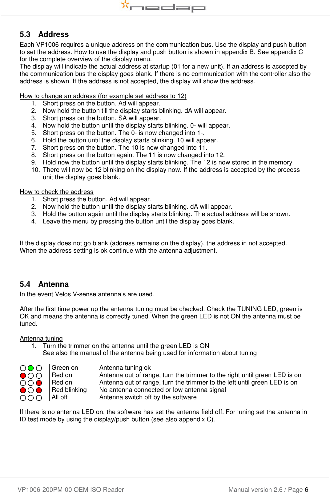
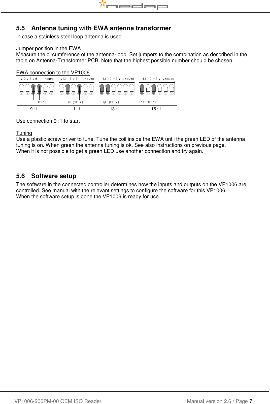
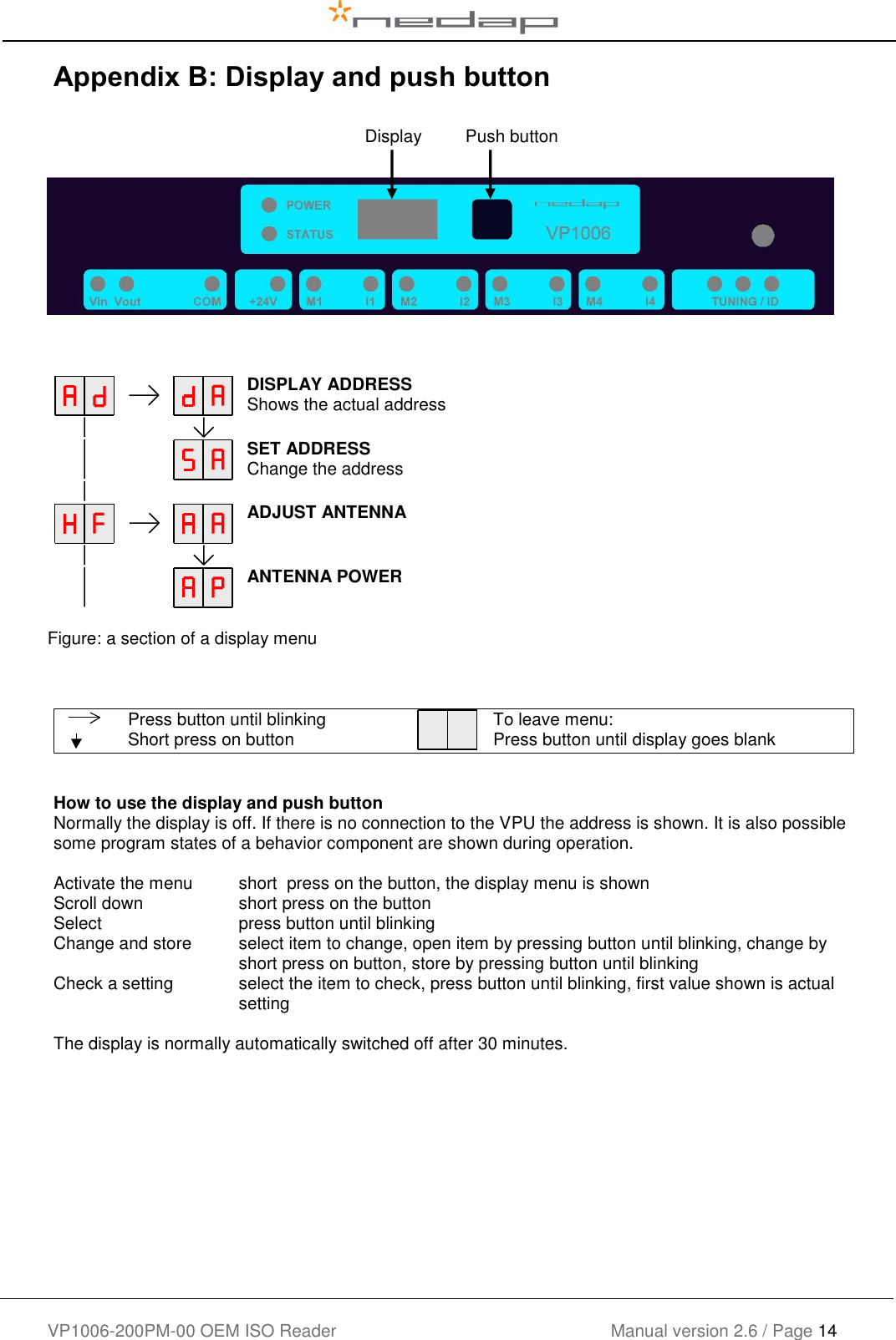
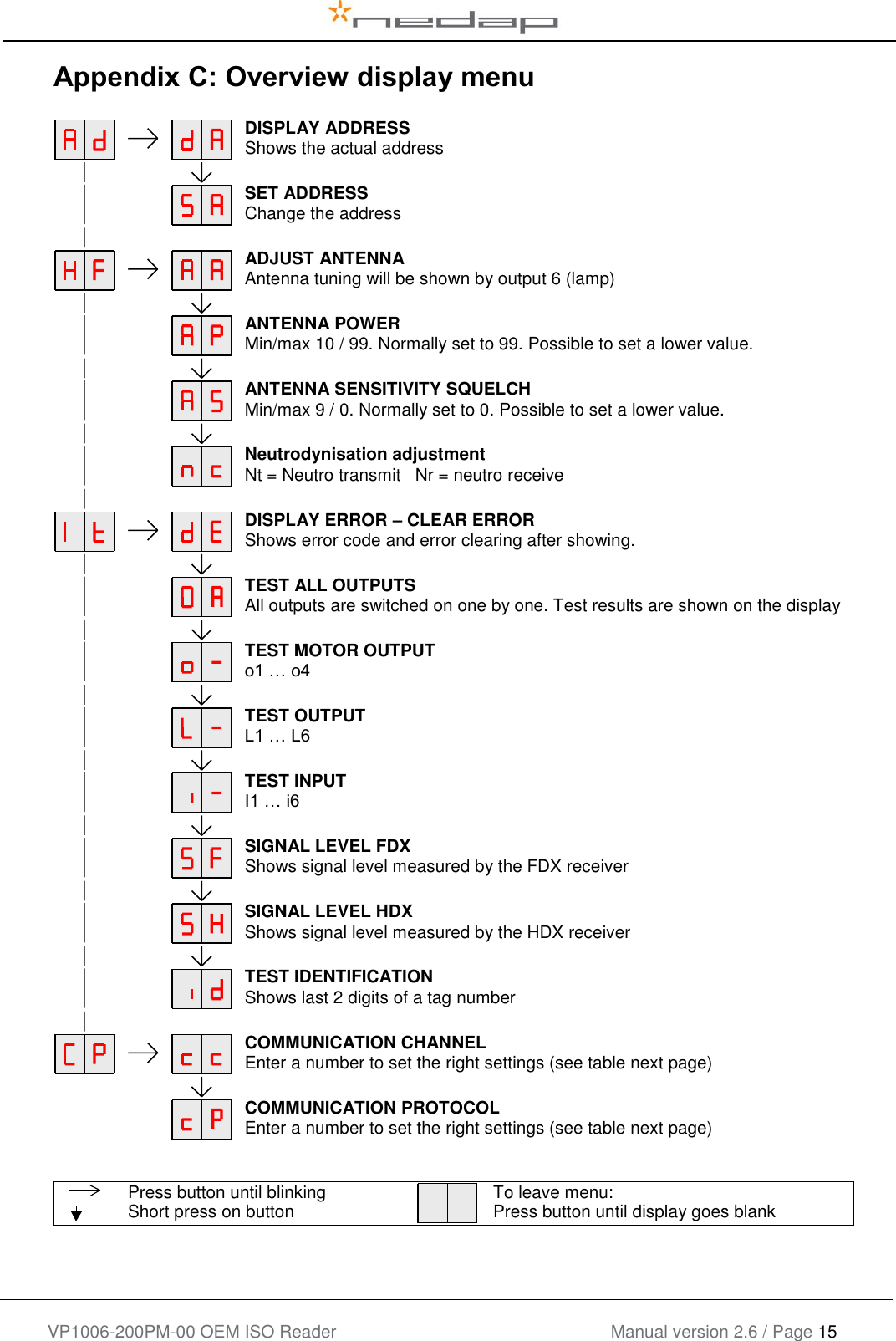
Manual
Manual
Navigation menu
Upload a User Manual
Namespaces
Wiki Guide
HTML
PDF
Info
Views
User Manual
Discussion / Help
Navigation