Nedap N V VELOS2 134 kHz Inductive proximity tag reader User Manual VP1006
N. V. Nederlandsche Apparatenfabriek NEDAP 134 kHz Inductive proximity tag reader VP1006
Contents
- 1. users manual
- 2. Manual
Manual
Service manual
For installation, operation and service
OEM ISO Reader
VP1006
06 - 2017 / Manual version 2.6

VP1006-200PM-00 OEM ISO Reader Manual version 2.6
Version overview
Manual version 2.0 / January 2008
Manual version 2.1 / September 2009
Chapter 7 : error codes 01 and 02 changed
Appendix E : shielding changed
Appendix F : shielding changed
Manual version 2.2 / 2-2012
Introduction : FCC tekst changed IC added
Appendix A : CE document added
Appendix C : Display changed to last software status
Manual version 2.3 / 4-2012
Neutrodynisation added, available since firmware 2.11.007
Chapter 6.2 : Neutrodynisation added
Appendix C : Display menu option Neutrodynisation added
Appendix I : Neutrodynisation unit between two antennas
Manual version 2.4 / 10-2013
Appendix C : Display menu option ISO protocol added
Manual version 2.5 / 06-2015
Appendix A : Updated product specifications
Manual version 2.6 / 06-2017
Updated FCC_IC Statement
This information is furnished for guidance, and with no guarantee as to its accuracy or completeness; its publication conveys no
license under any patent or other right, nor does the publisher assume liability for any consequence of its use; specifications and
availability of goods mentioned in it are subject to change without notice; it is not to be reproduced in any way, in whole or in
part, without the written consent of the publisher.
© Nedap N.V., Livestock Management P.O. Box 104 NL-7140 AC GROENLO The Netherlands

VP1006-200PM-00 OEM ISO Reader Manual version 2.6
VP1006 OEM ISO Reader
Contents
1 Introduction 1
2 Description and functioning 3
3 Safety 3
4 Installation 3
4.1 Mounting 3
4.2 Connections 4
5 Adjustments 5
5.1 Check after power up 5
5.2 Communication bus termination jumper 5
5.3 Address 6
5.4 Antenna 6
5.5 Antenna tuning with EWA antenna transformer 7
5.6 Software setup 7
6 Advanced 8
6.1 Testing inputs and outputs 8
6.2 Advanced antenna adjustment 9
6.3 Identification test options 10
7 Trouble shooting 11
8 Maintenance, cleaning and disposal 11
Appendix A: Specifications / CE 12
Appendix B: Display and push button 14
Appendix C: Overview display menu 15
Appendix D: LED indicator overview 17
Appendix E: RS485 connections with separated wiring 18
Appendix F: RS485 connections with Nedap Velos cable 19
Appendix G: RS232 connections 20
Appendix H: VP1006 connected to a Velos VP8001 (VPU) 21
Appendix I: Neutrodynisation unit between two antennas 22

VP1006-200PM-00 OEM ISO Reader Manual version 2.6
VP1006-200PM-00 OEM ISO Reader Manual version 2.6 / Page 1
Preface
This manual is part of the service documentation for Nedap Velos. Reference is also made to other
manuals that are part of the Nedap Velos documentation. For an overview of available Nedap Velos
manuals see the manual “Nedap Velos General Description”, or visit the Nedap Agri website
www.nedap-agri.com.
1 Introduction
The Velos VP1006 is used for identification of animals for feeding, weighing, milking, heat detection
etc. The VP1006 must be connected to a computer (controller) and can communicate by a CAN,
RS485 or RS232 protocol. The connected computer must give controlling commands to the VP1006 to
operate inputs, outputs and identification.
The VP1006 has the following main tasks:
- Identification of tags (ISO 134.2 kHz FDX/HDX)
- Controlling outputs - 6 outputs are available to activate e.g. lights, motors, valves, relays
- Reading inputs - 6 inputs available for e.g. sensors, switches
Following antenna types can be used:
- V-sense antennas
- EWA transformer with stainless steel antenna strip
- HDPE antenna with HDPE antenna tuner
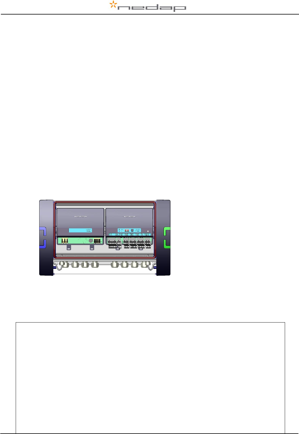
The VP1006 must be installed in a housing suitable for farm conditions, for example in a V-box.
Figure : V-box2 with a VP2002 power supply and a VP1006 reader
Reference manuals :
PS0000-200PM-00 Velos general description
VP1002-200PM-00 ISO-Booster
VP6001-200PM-00 V-sense
FCC ID: CGDVELOS2 and IC: 1444A-VELOS2
FCC_IC Statement
This device complies with part 15 of the FCC Rules and with Industry Canada’s licence-exempt RSSs.
Operation is subject to the following two conditions:
(1) this device may not cause interference, and
(2) this device must accept any interference, including interference that may cause undesired operation of the device.
Warning (15.21)
Changes or modifications not expressly approved by the party responsible for compliance could void the user’s authority to
operate the equipment.
Cet appareil se conforme aux normes RSS exemptés de license du Industry Canada. L'opération est soumis aux deux
conditions suivantes:
(1) cet appareil ne doit causer aucune interférence, et
(2) cet appareil doit accepter n'importe quelle interférence, y inclus interférence qui peut causer une opération non pas voulu de
cet appareil.
Les changements ou modifications n’ayant pas été expressément approuvés par la partie responsable de la conformité peuvent
faire perdre à l’utilisateur l’autorisation de faire fonctionner le matériel.

VP1006-200PM-00 OEM ISO Reader Manual version 2.6 / Page 2
FCC and ISED Radiation Exposure Statement
This equipment complies with FCC (OET Bulletin 65) and Canadian radiation exposure limits set forth in RSS-102 for a
uncontrolled environment. This equipment should be installed and operated with a minimum distance of 20 cm between the
radiator and your body. This transmitter must not be co-located or operating in conjunction with any other antenna or transmitter.
Cet équipement est conforme a RSS-102 limites énoncées pour un environnement non contrôlé. Cet équipement doit être
installé et utilisé avec une distance minimale de 20 cm entre le radiateur et votre corps.
ISED EMC Declaration
This Class B digital apparatus complies with Canadian ICES-003.
Cet appareil numérique de Classe B est conforme à la norme Canadienne ICES-003.
FCC Information to the user (15.105(b))
Note: This equipment has been tested and found to comply with the limits for a class B digital devices, pursuant to part 15 of the
FCC Rules. These limits are designed to provide reasonable protection against harmful interference in a residential installation.
This equipment generates, uses and can radiate radio frequent energy and, if not installed and used in accordance with the
instructions, may cause harmful interference to radio communications.
However, there is no guarantee that interference will not occur in a particular installation. If this equipment does not cause
harmful interference to radio or television reception, which can be determine by turning the equipment off and on, the user is
encouraged to try to correct the interference by one or more of the following measures:
• Reorient or relocate the receiving antenna.
• Increase the separation between the equipment and receiver.
• Connect the equipment into an outlet on a circuit different from that to which the receiver.
• Any changes or modifications not expressly approved by the party responsible for compliance could void the
user's authority to operate the equipment.
• To ensure compliance with FCC regulations, use only the shielded interface cables provided with the
product, or additional specified components or accessories that can be used with the installation of the
product
NOTE:
Antenna VP6041 has the same dimensions as the VP6042.
VP6041 and VP6042 regarding hardware are the same. The VP6041 is adjusted for environments with lots of steel for short distances (pigs). The
VP6042 is adjusted for longer distances (1 m) recognition (Cows).

VP1006-200PM-00 OEM ISO Reader Manual version 2.6 / Page 3
2 Description and functioning
A VP1006 has 6 inputs used for reading e.g. sensors or switches.
There are also 6 outputs available to activate e.g. lights, motors, valves or relays.
The VP1006 can read tags FDX/HDX 134.2 kHz.
The VP1006 must be connected to a computer and can communicate by a CAN, RS485 or RS232
protocol. The connected computer must give controlling commands to the VP1006 to operate inputs,
outputs and identification.
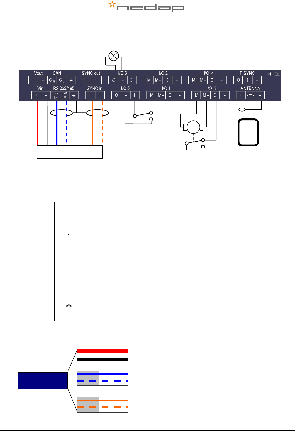
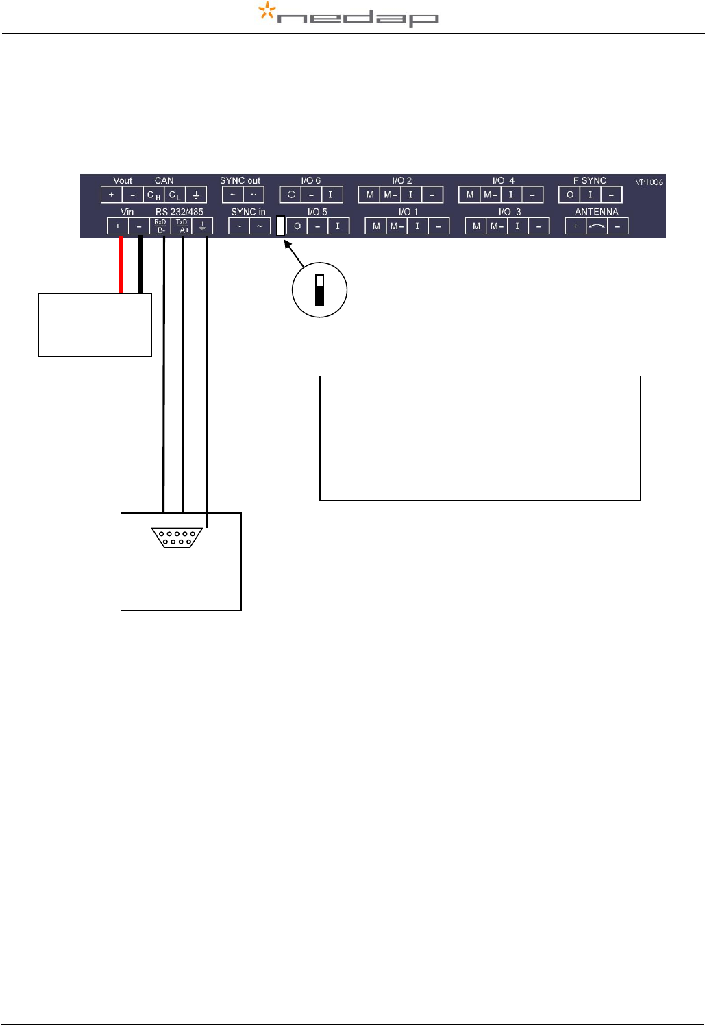
Figure : Sticker on the VP1006 with indication of the connections
Input/output 1 to 4 ( I/O 1 till I/O 4 ) can be used to control feed motors or can be used as normal
input/output. Output/input 5 and 6 ( I/O 5 - I/O 6 ) can only be used as output/input, not for feed motors.
Operation of the VP1006
Antenna : for reading tags, normally on
Inputs : read continuously with status change sent to the controller
Outputs : switched on or off by commands from the controller
LEDs : switched on or off by the VP1006 according to the status
Error : errors are sent to the controller
All inputs and outputs can be tested by the use of the push button and display. For operation of the
push button and display see appendix B.
3 Safety
Installation and service only by trained personnel.
Always turn off the main power when working on the electrical installation.
4 Installation
Installation consits of the following steps:
1. Mounting
2. Installation of all wiring (connections)
3. Power up
4. Set address (when more then one VP1006)
5. Set communication protocol
6. Antenna adjustment (green LED on)
7. Checking the connected equipment like lamps, motors, sensors etc.
8. Configuration in the PC
Follow this manual to complete the steps.
4.1 Mounting
See the relevant equipment manual relating to where the VP1006 is to be installed.
VP1006-200PM-00 OEM ISO Reader Manual version 2.6 / Page 4
4.2 Connections
See the relevant equipment manual relating to where the VP1006 is to be installed. See also appendix
E, F and G for the different connection possibilities.
Figure : I/O of the VP1006. The feed motor, input and output connections are shown above as an
example.
Details VP1006 inputs and outputs
Vin
+
Power
-
Minus
RS232 / 485
RxD / B-
Data receive
TxD / A+
Data send
Shield of RS232 / 485
SYNC
~
Synchronisation for HDX, AC (no plus or minus, cable must be twisted pair)
~
See above
I/O 1 .. 4
M
Motor output or normal output max 3A
M-
Minus for motor output or normal output
I
Input of motor or normal input
-
Minus for motor input or normal input
I/O 5 .. 6
O
Output max 250mA
-
Minus for output (O) and minus input (I)
I
Input
ANTENNA
+
Antenna with external adjustment
Antenna with no adjustment
-
Antenna minus (shield of coax cable)
F SYNC
Frequency synchronisation (not used yet)
IMPORTANT : Use power supply with a fused output such as Velos VP2001, VP2002.
Details Velos cable
M
orange
blue white
blue
black
red
orange white
green
red
white
brown
Velos cable
Switch
Light
Feed motor
Red (+)
Black (-)
Blue (Ch)
Blue/white (Cl)
Shield
Orange (Sync)
Orange/white (Sync)
Shield
Power
1,5 mm2
Communication
0,34 mm2
Twisted pair shielded
HF Synchronisation
0,34 mm2
Twisted pair shielded
Part No. 7705310
VP1006-200PM-00 OEM ISO Reader Manual version 2.6 / Page 5
5 Adjustments
Before starting with adjustments first install all components and wiring. Follow the sequence as
indicated in this chapter.
5.1 Check after power up
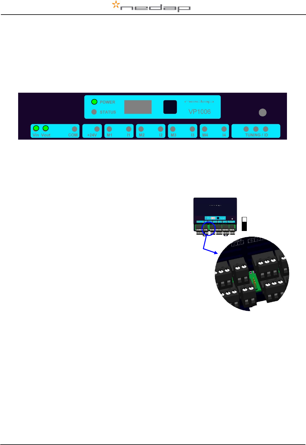
Check if the VP1006 has power after power up. This means 3 green LED’s are on, see figure below.
For more details about the LED indicators see Appendix D.
If LED’s are green, continue with address settings
5.2 Communication bus termination jumper
Termination is only used in case of RS485 communication.
When using RS485: at the last VP1006 in the communication
line (bus) the jumper must be set to the other position. Also at
the beginning of the line (computer) termination is required.
For RS232 and CAN always use default jumper position
Check LED “COM” to evaluate the connection to the computer.
Default
Jumper
position

VP1006-200PM-00 OEM ISO Reader Manual version 2.6 / Page 6
5.3 Address
Each VP1006 requires a unique address on the communication bus. Use the display and push button
to set the address. How to use the display and push button is shown in appendix B. See appendix C
for the complete overview of the display menu.
The display will indicate the actual address at startup (01 for a new unit). If an address is accepted by
the communication bus the display goes blank. If there is no communication with the controller also the
address is shown. If the address is not accepted, the display will show the address.
How to change an address (for example set address to 12)
1. Short press on the button. Ad will appear.
2. Now hold the button till the display starts blinking. dA will appear.
3. Short press on the button. SA will appear.
4. Now hold the button until the display starts blinking. 0- will appear.
5. Short press on the button. The 0- is now changed into 1-.
6. Hold the button until the display starts blinking. 10 will appear.
7. Short press on the button. The 10 is now changed into 11.
8. Short press on the button again. The 11 is now changed into 12.
9. Hold now the button until the display starts blinking. The 12 is now stored in the memory.
10. There will now be 12 blinking on the display now. If the address is accepted by the process
unit the display goes blank.
How to check the address
1. Short press the button. Ad will appear.
2. Now hold the button until the display starts blinking. dA will appear.
3. Hold the button again until the display starts blinking. The actual address will be shown.
4. Leave the menu by pressing the button until the display goes blank.
If the display does not go blank (address remains on the display), the address in not accepted.
When the address setting is ok continue with the antenna adjustment.
5.4 Antenna
In the event Velos V-sense antenna’s are used.
After the first time power up the antenna tuning must be checked. Check the TUNING LED, green is
OK and means the antenna is correctly tuned. When the green LED is not ON the antenna must be
tuned.
Antenna tuning
1. Turn the trimmer on the antenna until the green LED is ON
See also the manual of the antenna being used for information about tuning
Green on
Antenna tuning ok
Red on
Antenna out of range, turn the trimmer to the right until green LED is on
Red on
Antenna out of range, turn the trimmer to the left until green LED is on
Red blinking
No antenna connected or low antenna signal
All off
Antenna switch off by the software
If there is no antenna LED on, the software has set the antenna field off. For tuning set the antenna in
ID test mode by using the display/push button (see also appendix C).
VP1006-200PM-00 OEM ISO Reader Manual version 2.6 / Page 7
5.5 Antenna tuning with EWA antenna transformer
In case a stainless steel loop antenna is used.
Jumper position in the EWA
Measure the circumference of the antenna-loop. Set jumpers to the combination as described in the
table on Antenna-Transformer PCB. Note that the highest possible number should be chosen.
EWA connection to the VP1006
9 : 1 11 : 1 13 : 1 15 : 1
Use connection 9 :1 to start
Tuning
Use a plastic screw driver to tune. Tune the coil inside the EWA until the green LED of the antenna
tuning is on. When green the antenna tuning is ok. See also instructions on previous page.
When it is not possible to get a green LED use another connection and try again.
5.6 Software setup
The software in the connected controller determines how the inputs and outputs on the VP1006 are
controlled. See manual with the relevant settings to configure the software for this VP1006.
When the software setup is done the VP1006 is ready for use.

VP1006-200PM-00 OEM ISO Reader Manual version 2.6 / Page 8
6 Advanced
Tests and adjustments described in this chapter are not used for a standard startup and configuration
of the VP1006.
6.1 Testing inputs and outputs
There are two types of output tests. An output test to switch the output on and off, and an output test
especially for Nedap feed motors. There is also available an input test for checking connected
equipment like switches and sensors.
Use the display and push button for testing, see appendix B how to use it.
Feed motor test
Use the motor test o1, o2, o3 or o4 to test a feed motor.
This is a combination of an input and output test. When the test is finished the test results are shown
as code on the display (blinking). Test all outputs ”0A” will test all outputs one by one.
Code on the display
Description motor test results
00
Motor run ok
01
Output already in use
02
No motor current measured
03
No input signal seen
04
-
05
-
06
Motor current too high for too long
07
-
08
Current still measured after test has stopped
09
Output voltage is stopped due to motor safeguard function
10
Output already in use
11
-
12
Motor current too low while running
Example of a feed motor test (connected to output 1)
1. Short press on the button until “It” appears.
2. Now hold the button until the display starts blinking. “dE” will appear.
3. Short press on the button 2 times. “o1” will appear.
4. Now hold the button until the display starts blinking. Output 1 will be switched on. When ready
the test result are shown on the display.
Output test
Use the test L1, L2, .. L6 to test the connected equipment e.g. lights, valves or relays. This test will
switch on the selected output. The test is stopped by a short press on the button.
Example of a light test (connected to output 6)
1. Short press on the button until “It” appears.
2. Now hold the button until the display starts blinking. “dE” will appear.
3. Short press on the button until “L6” appears.
4. Now hold the button until the display starts blinking. Output 6 will be switched on. To switch off,
a short press on the button.
Input test
Use the test i1, i2, .. i6 to test the connected equipment e.g. switches and sensors. This test will read
the selected input. The results are indicated with a “0” or “1”. Open or closed depends on the settings
from the behavior component. The test is stopped by a short press on the button.
Example of a switch test (connected to output 5)
1. Short press on the button until “It” appears.
2. Now hold the button till the display starts blinking. “dE” will appear.
3. Short press on the button until “i5” appears.
4. Now hold the button until the display starts blinking. Input 5 will be read.
5. Activate the switch on and off. If ok, the display value will show zero and one

VP1006-200PM-00 OEM ISO Reader Manual version 2.6 / Page 9
6.2 Advanced antenna adjustment
Antenna power
The antenna power default is set to maximum (99) and needs no adjustments.
Lowering the antenna power will reduce the reading distance of the antenna.
Check the antenna power
The antenna power level is shown on the display in the service menu at HF option AP (Adjust Power)
1. Select menu option AP (Adjust Power) on the display by using the push button
2. Push the button until the display starts to blink, a value will appear on the display
3. The value on the display is the actual power setting. 99 is the default factory setting.
4. To leave the menu without modifying the settings press the button until the display goes blank
(press about 4 seconds)
Modify the antenna power
1. Select the actual antenna power on the display (see above antenna power check)
2. Short press on the button and the first digit of the value will change
3. Continue to press until the desired value, then hold the button until blinking
4. The second digit can be changed in the same way
5. When the desired value is on the display, press until the display blinks
6. The next menu item AS is now indicated.
7. To leave the service menu and return to normal operation, press the button until the display
goes blank (press about 4 seconds)
Antenna squelch
Antenna squelch is a possibility to set a threshold for the ID level of a tag. It means the antenna power
is still the same, but the software will not transfer weak received tag numbers.
The antenna squelch default is set to minimum (-0). This means no threshold. Maximum is -9.
Check the antenna squelch level
The antenna squelch level is shown on the display in the service menu at HF, option AS (Adjust
Squelch)
1. Select menu option AS (Adjust Squelch) on the display by using the push button
2. Push the button until the display starts to blink, a value will appear on the display
3. The value on the display is the actual setting. -0 is the default factory setting.
4. To leave the menu without modifying the settings press the button until the display goes blank
(press about 4 seconds)
Modify the antenna squelch level
1. Select the actual antenna squelch level on the display (see above squelch level check)
2. Short press on the button and the value will change
3. Continue to press until the desired value, then hold the button until blinking
4. The next menu item “df” is now indicated.
5. Hold a tag in the antenna and determine the maximum reading distance
6. If reading distance is ok leave the menu. If not ok try another level.
7. To leave the service menu and return to normal operation, press the button until the display
goes blank (press about 4 seconds)

VP1006-200PM-00 OEM ISO Reader Manual version 2.6 / Page 10
Antenna tuning with option “AA”
With HF menu option “Adjust Antenna (AA)”, it is possible to see the antenna tuning on the display.
The highest display value is the optimum adjustment.
How to tune
1. Select option “AA” on the display and press the button until the display starts to blink. A value
will now appear on the display.
2. Now turn the antenna trimmer slowly (on the antenna). The display value will change. If the
value is going down, turn the other way. Turn till the maximum display value is found.
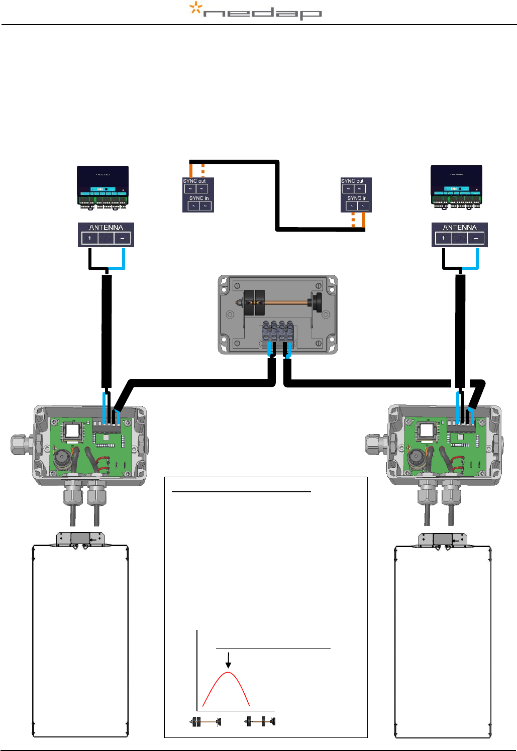
Neutrodynisation between two antennas
Two large antennas can have coupling with antenna fields. Result : tag is identified in both antennas. A
solution is to install a neutrodynisation unit to reduce cross talk caused by antenna coupling.
How to tune
1. Set reader A in neutro transmit mode (HF menu option nc - nt).
2. Set reader B in neutro receive mode
(HF menu option nc - nr)
3. Turn the wheels apart to the highest display value at reader B
The display value and wheel distance apart can vary. Low display value means usually low coupling.
Always use a sync cable between the readers. It is used during normal operation and also used for the
tuning to switch of transmitter of the receive unit. If one unit is set to neutro transmit, it will switch off all
other readers connected to the same sync cable.
Antenna tuning visible by a light
With HF menu option “Adjust Antenna (AA)” output 6 is also switched on. By connecting a light to
output 6 the status during tuning can be monitored. When the light is blinking it is indicating the
optimum adjustment point and is corresponding with the highest display value.
6.3 Identification test options
Identification test with option “id”
When a tag is in the antenna field, the green LED used for the antenna tuning will be blinking. There is
also a test in the internal test menu called “id”. This test will also show the green LED blinking but also
shows the last two digits of the tag number on the display.
Signal level indication option “SF” and “SH”
There is a test available to give an indication about the signal received on the reader of the VP1006.
This test is separated in a FDX (SF) and HDX (SH) noise indication test. This test is mainly used for
HDX because at HDX there is a greater risk of external influence on the antenna field.
How to use the signal level test
1. Select option “SH” on the display and press the button until the display starts to blink. A value
will appear on the display.
2. Now move a HDX tag slowly into the antenna field. The display value will normally increase
when getting closer to the antenna. If there is negligible or little increase in display value this is
an indication something external is causing noise.
The possible cause of noise can be frequency controlled electric motors or a transmitter operating on
or close to 134.2 kHz

VP1006-200PM-00 OEM ISO Reader Manual version 2.6 / Page 11
7 Trouble shooting
Errors / malfunctioning is indicated by the indicator LED’s or the display.
Error by indicator LED
Indicator LED’s are normally green or switched off. A red or orange indicator LED means normally
there is something not ok. See Appendix D for the explanation of the different colors.
Errors indicated at menu option “dE”
In menu option “dE” it is possible to see actual error codes. When entering the display menu option
“dE” the errors code will be shown and the error will be cleared. If the error is not cleared it means
there is still an error. There can be more than one error. Further errors are displayed one after another
with a short delay between each code.
“dE” code on the display
Description
00
No errors
01
Max time for motor exceeded
02
Max motor current error
03
-
04
-
05
Outputs switched off due to high motor current
06
Software switched off due to current and time
07
Output switched off due to current, time and also output active
08
Input of motor output seen X times while motor is not active
09
Motor 1 error
10
Motor 2 error
11
Motor 3 error
12
Motor 4 error
13
Vout overload
14
Output 5 shut off due to overload
15
Output 6 shut off due to overload
16
Software switched off due to max current and time
17
CAN–bus over voltage
18
Voltage to next module switched off
Identification performance and disturbance
Identification performance can be reduced by disturbance caused by variable-frequency drives used
for ventilation, milk pumps, vacuum pumps, etc. Also ballasts used for fluorescent tube lighting may
interfere. If there is interference one can locate the source by switching off all the equipment on a farm
and then switch them on again one by one. Most of the time when a variable-frequency drive is
causing a problem it is due to bad installation or without the mandatory main filters.
8 Maintenance, cleaning and disposal
Maintenance
No regular maintenance required.
Software update
A VP1006 is equipped with software to activate inputs and outputs, display / push button and a motor
safeguard. This software is called firmware. During manufacturing the firmware is programmed and
ready for use. In case of an update it is possible to download new firmware thru the CAN-bus. In the
Velos system the web browser interface of the VPU (VP8001) is used to handle this. For more details
about downloading new firmware see also the manual of the VPU (VP8001).
Cleaning
A VP1006 must be installed in a suitable housing (V-box) so cleaning of the VP1006 is not required.
Disposal
Discard according to the regulations prevailing at the time of disposal
VP1006-200PM-00 OEM ISO Reader Manual version 2.6 / Page 12
Appendix A: Specifications / CE
Specifications VP 1006
Dimensions
143 x 120 x 68 mm LxWxH (excluding mounting rail) Weight: ± 360 gr
CAN
CAN-bus communication 125 kBit
Power
Input voltage 25 VDC, +20% -20%
Min power consumption 300 mA with antenna switched on
Maximum power consumption 2,5 A
Protected against reverse connection power supply
Software
Downloadable by the CAN network
Inputs
Reading inputs, analog (0-40V) and digital. Suitable for NPN and PNP sensors.
Outputs
Max. 2.5 Amp by current limiter, short-circuiting protected Motor safe-guard (after 25
sec)
Antennas
800 µH. Different types possible.
Detection distance
Varies per antenna
Synchronisation
Synchronisation according to ISO 11785
Environment
Temperature: Operating: -10 – 50 °C, Storage: -25 – 70 °C
Relative humidity: 10 – 93% non condensing
Maximum noise level: 10 dBµA/m quasi peak, according CISPR 16-1-1
Conducted noise: according EN55022
IP class
IP 30. When installed in V-box IP 65 (cover and cables installed correctly !)
Always use a NEDAP power supply. The Nedap guarantee-regulations are only valid when is installed as
indicated in this manual. Install data cables at a safe distance from (high) powered cables
For more detailed information contact your local Nedap supplier or check the internet site.

VP1006-200PM-00 OEM ISO Reader Manual version 2.6 / Page 13
VP1006-200PM-00 OEM ISO Reader Manual version 2.6 / Page 14
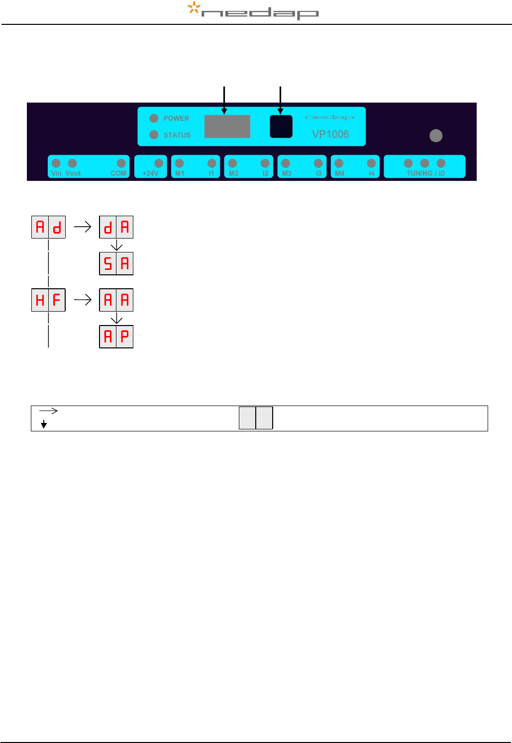
Appendix B: Display and push button
DISPLAY ADDRESS
Shows the actual address
SET ADDRESS
Change the address
ADJUST ANTENNA
ANTENNA POWER
Figure: a section of a display menu
Press button until blinking
Short press on button
To leave menu:
Press button until display goes blank
How to use the display and push button
Normally the display is off. If there is no connection to the VPU the address is shown. It is also possible
some program states of a behavior component are shown during operation.
Activate the menu short press on the button, the display menu is shown
Scroll down short press on the button
Select press button until blinking
Change and store select item to change, open item by pressing button until blinking, change by
short press on button, store by pressing button until blinking
Check a setting select the item to check, press button until blinking, first value shown is actual
setting
The display is normally automatically switched off after 30 minutes.
Display Push button
VP1006-200PM-00 OEM ISO Reader Manual version 2.6 / Page 15
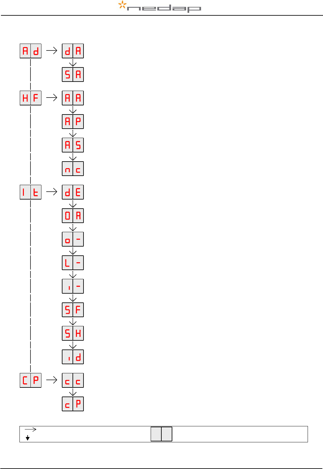
Appendix C: Overview display menu
DISPLAY ADDRESS
Shows the actual address
SET ADDRESS
Change the address
ADJUST ANTENNA
Antenna tuning will be shown by output 6 (lamp)
ANTENNA POWER
Min/max 10 / 99. Normally set to 99. Possible to set a lower value.
ANTENNA SENSITIVITY SQUELCH
Min/max 9 / 0. Normally set to 0. Possible to set a lower value.
Neutrodynisation adjustment
Nt = Neutro transmit Nr = neutro receive
DISPLAY ERROR – CLEAR ERROR
Shows error code and error clearing after showing.
TEST ALL OUTPUTS
All outputs are switched on one by one. Test results are shown on the display
TEST MOTOR OUTPUT
o1 … o4
TEST OUTPUT
L1 … L6
TEST INPUT
I1 … i6
SIGNAL LEVEL FDX
Shows signal level measured by the FDX receiver
SIGNAL LEVEL HDX
Shows signal level measured by the HDX receiver
TEST IDENTIFICATION
Shows last 2 digits of a tag number
COMMUNICATION CHANNEL
Enter a number to set the right settings (see table next page)
COMMUNICATION PROTOCOL
Enter a number to set the right settings (see table next page)
Press button until blinking
Short press on button
To leave menu:
Press button until display goes blank
VP1006-200PM-00 OEM ISO Reader Manual version 2.6 / Page 16
CP-menu communication possibilities
RS232 with Nedap extended protocol
RS232
20
Nedap extended protocol 2400 Baud
21
Nedap extended protocol 9600 Baud
22
Nedap extended protocol 19200 Baud
23
Nedap extended protocol 38400 Baud
24
ISO
RS232
20
ISO protocol 2400 Baud
31
ISO protocol 9600 Baud
32
ISO protocol 19200 Baud
33
ISO protocol 38400 Baud
34
RS485 with Nedap extened protocol
RS485
Bias off - no. of breaks 0
40
Nedap extended protocol 2400 Baud
21
RS485
Bias on - no. of breaks 0
41
Nedap extended protocol 9600 Baud
22
RS485
Bias off - no. of breaks 2
42
Nedap extended protocol 19200 Baud
23
RS485
Bias on - no. of breaks 2
43
Nedap extended protocol 38400 Baud
24
RS485
Bias off - no. of breaks 4
44
RS485
Bias on - no. of breaks 4
45
RS485
Bias off - no. of breaks 6
46
RS485
Bias on - no. of breaks 6
47
RS485
Bias off - no. of breaks 8
48
RS485
Bias on - no. of breaks 8
49
RS232 with Texas Instruments protocol*
RS232
20
Texas Instruments protocol
10
*Serie 2000 reader systems ASCII protocol, 9600 baud, 8 databits, no parity, 1 stopbit
Default factory settings: RS232, nedap extended protocol 9600 baud (CC=20 and CP=22)
VP1006-200PM-00 OEM ISO Reader Manual version 2.6 / Page 17
Appendix D: LED indicator overview
POWER
Green on
Power on
off
No power
STATUS
Blue
Slow blinking
Fast blinking
1 short flash
2 short flashes
3 short flashes
Operating ok
Downloading or error during download
V-pack not coupled
Firmware present but not active
No firmware present
Display
on
Address indicated
No communication
off
Communication status ok
V in
Green on
Input power applied
off
No power
Orange
Low power, less than 20V
Orange blinking
Wrong CAN-bus connection, Vin and Vout swapped
Red
Error, plus and minus swapped
V out
Green on
Output power
off
No power
Orange blinking
Low power
Red blinking
Error, plus and minus swapped
COM
Green on
V-pack is last one on the bus
off
V-pack is not last one on the bus
Orange blinking
CAN-bus error and last V-pack on the bus
Red
CAN-bus error
Red blinking
CAN-bus warning / connected wrong
+24V
Green on
24V output switched on
off
Output switched off
M1 .. M4
Green on
Output on
off
Output off
Red blinking
Output error
I1 .. I4
Green on
Input contact open
off
Input contact closed
TUNING /ID
Green on
Green blinking
Antenna ok
Antenna ok and tag identified
Red on
Antenna not tuned correctly
Red on
Antenna not tuned correctly
Red blinking
Antenna error / not connected
VP1006-200PM-00 OEM ISO Reader Manual version 2.6 / Page 18
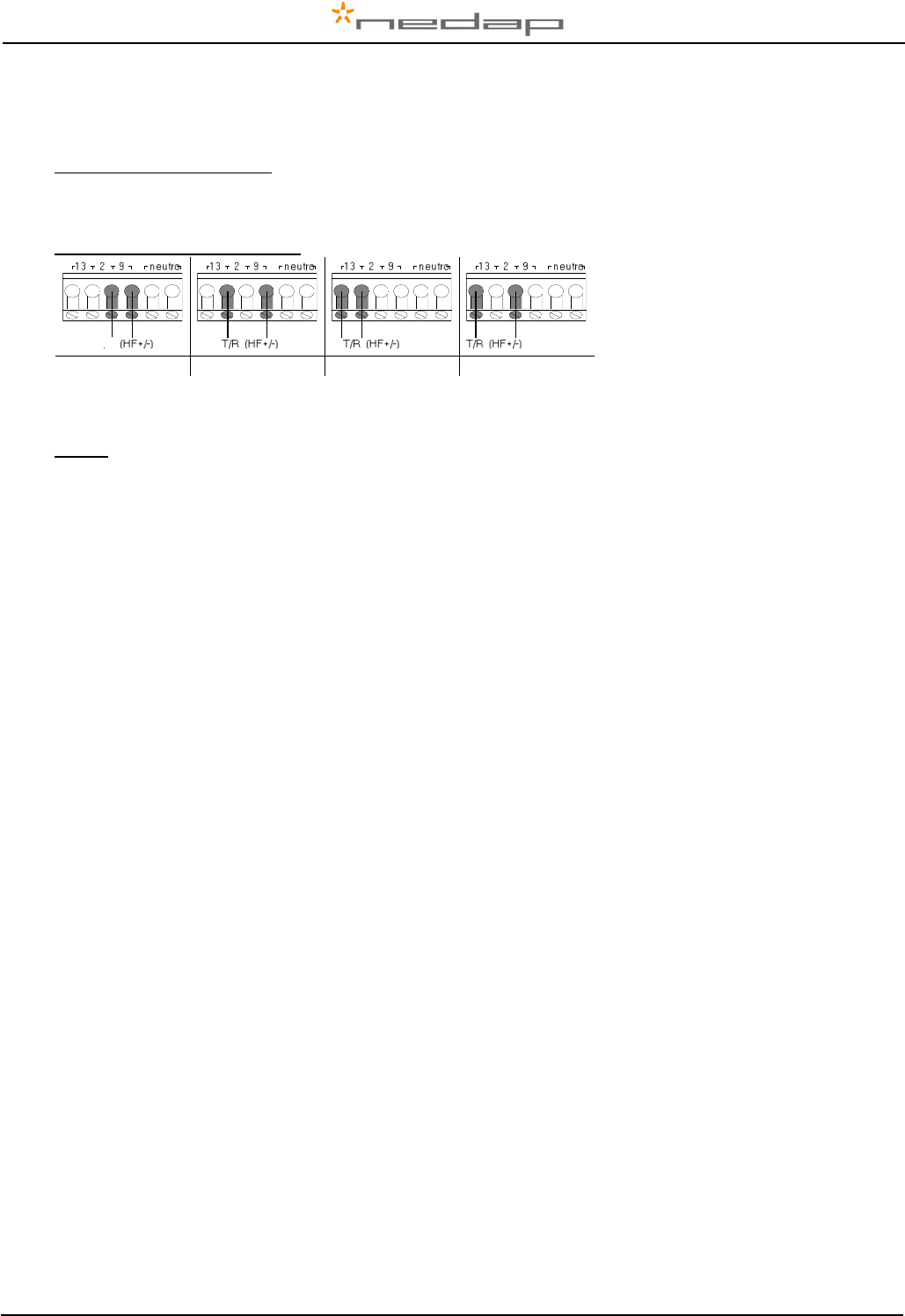
Appendix E: RS485 connections with separated wiring
VP1006 (1)
RS485 cable
A
B
(2)
(n)
red
black
orange
orange/white
shield
red
black
orange
orange/white
shield
red
black
orange
orange/white
shield
red
black
shield
red
black
orange
orange/white
shield
To RS485
interface
of computer
Last VP1006 : Jumper up !!
RS485 cable specifications (PC to first VP1006):
Wires : min. 0.34 mm2 twisted pair shielded
Max length between PC and last VP1006 1200m
Velos cable
Max length Velos cable 80 meter from power supply
to last VP1006
Max. number of VP1006
32 (incl computer)
Velos cable
Power
Supply
(VP2001-
VP2002)
Shield not connected
Shield not connected
VP1006-200PM-00 OEM ISO Reader Manual version 2.6 / Page 19
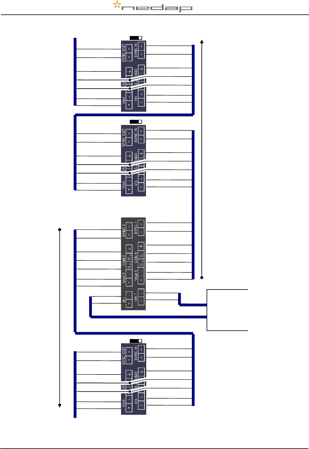
Appendix F: RS485 connections with Nedap Velos cable
IMPORTANT : avoid short circuit of shields, install protection around the end of the shields.
red
black
orange
orange/white
red
black
orange
orange/white
blue
blue/white
shield
red
black
orange
orange/white
red
black
blue
blue/white
shield
red
black
orange
orange/white
blue
blue/white
shield
B
A
To RS485
interface
of computer
blue
blue/white
shield
B
A
shield
blue
blue/white
shield
B
A
RS485 cable specifications (PC to first VP1006):
Wires : min. 0.34 mm2 twisted pair shielded
Max length between PC and last VP1006 1200m
Velos cable
Max length Velos cable 80 meter from power supply
to last VP1006
Max. number of VP1006
32 (incl computer)
Velos cable
Last VP1006 : Jumper up !!
Power
Supply
(VP2001-
VP2002)
VP1006-200PM-00 OEM ISO Reader Manual version 2.6 / Page 20
Appendix G: RS232 connections
RS 232 port of
computer
TxD pin3
RxD pin2
GND pin5
RS232 cable specifications :
Shielded cable
Wires min. 0.34 mm2
Max length between PC and VP1006 15 meters
Power supply
Communication jumper
VP1006-200PM-00 OEM ISO Reader Manual version 2.6 / Page 21
Appendix H: VP1006 connected to a Velos VP8001 (VPU)
VP8001
(V-pu)
VP1006
VP1006
VP1006
next
next
red
black
orange
orange/white
blue
blue/white
red
black
orange
orange/white
blue
blue/white
shield
shield
red
black
orange
orange/white
blue
blue/white
shield
red
black
orange
orange/white
blue
blue/white
shield
red
black
orange
orange/white
blue
blue/white
red
black
orange
orange/white
blue
blue/white
shield
shield
CAN channel 2
CAN channel 1
red
black
orange
orange/white
blue
blue/white
red
black
orange
orange/white
blue
blue/white
shield
shield
red
black
Power
supply
(VP2001)
red
black
VP1006-200PM-00 OEM ISO Reader Manual version 2.6 / Page 22
Appendix I: Neutrodynisation unit between two antennas
Two large antennas can have coupling with antenna fields. Result : tag is identified in both antennas. A
solution is to install a neutrodynisation unit.
Required equipment:
- Readers with the option Neutro in the HF menu
- A neutrodynisation unit
- Coax cable, specification RG58
- Cable between the readers to connect SYNC OUT and SYNC IN
shield
core
shield
core
READER A
READER B
Display value (0- 99)
Turn to max display value
Neutrodynisation adjustment
1. Set reader A in neutro transmit mode
(HF menu option nc - nt)
2. Set reader B in neutro receive mode
(HF menu option nc - nr)
3. Turn the wheels apart to the highest
display value at reader B
The display value and wheel distance
apart can vary. Low display value means
usually low coupling.
COAX RG58
COAX RG58
COAX RG58
COAX RG58
Neutrodynisation unit