Nedap N V VELOS2 Inductive Proximity Tag Reader User Manual users manual
N. V. Nederlandsche Apparatenfabriek NEDAP Inductive Proximity Tag Reader users manual
Contents
- 1. users manual
- 2. Manual
users manual
VP1002-200PM-00 ISO Booster 4-2007/1.0
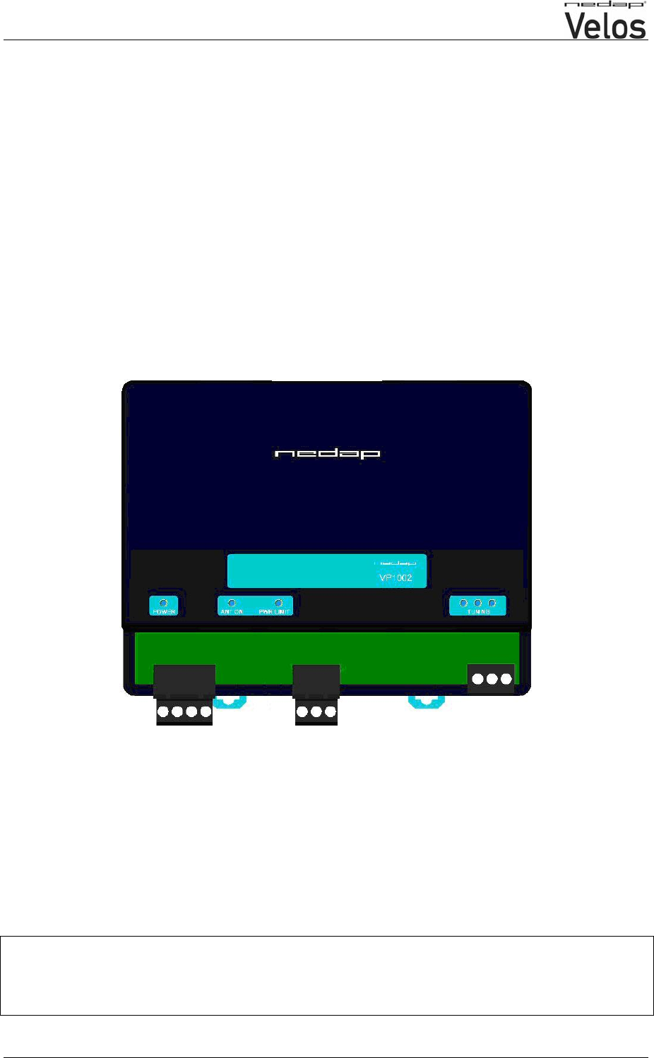
VP1002
ISO-Booster
This information is furnished for guidance, and with no guarantee as to its accuracy or completeness; its publication conveys no
licence under any patent or other right, nor does the publisher assume liability for any consequence of its use; specifications and
availability of goods mentioned in it are subject to change without notice; it is not to be reproduced in any way, in whole or in
part, without the written consent of the publisher.
© Nedap N.V., AGRI P.O. Box 104 NL-7140 AC GROENLO The Netherlands
VP1002-200PM-00 ISO Booster 4-2007/1.0 Page 2 of 4
VP1002
ISO-Booster
General
The ISO Booster or VP1002 is used for improving reading distance of antennas specially in case of
using small (ear) tags. The ISO Booster must be connected to a V-pack with identification.
This device complies with Part 15 of the FCC Rules. Operation is subject to the following two
conditions: (1) this device may not cause harmful interference, and (2) this device must accept
any interference received, including interference that may cause undesired operation.
Connections
Cable specifications
A Min. 0.5 mm2 L.max 20m
B Coax RG 58 L.max 100m. Shield connected to minus.
C Coax RG 58 L.max 100m. Shield connected to minus.
POWER + Input voltage from V-pack 24 VDC, +20% -20%
- Minus of V-pack
READER - Not used
+ To antenna input of V-pack
- To minus of antenna input from V-pack (shield of coax cable)
ANTENNA - Not used
+ Antenna
- Antenna minus (shield of coax cable)
VP1002-200PM-00 ISO Booster 4-2007/1.0 Page 3 of 4
LED indicators
POWER Green on Power on
Off No power
ANT ON Blue Antenna switch on by connected V-pack
Off Antenna switch off by connected V-pack
PWR LIMIT Red on Antenna power to high, safety circuit activated
Off Antenna power ok
TUNING Green on
Green blinking Antenna adjustment ok
Antenna ok and tag identified
Red on Antenna not tuned correctly, turn the screw “in”
Red on Antenna not tuned correctly, turn the screw “out”
Red blinking Antenna error / not connected
All off Antenna switch off by the software
Adjustment of the VP1002
The adjustment consists of 2 steps.
1. Tuning the antenna
2. Set the antenna power level
Step 1 : Tuning the antenna
The antenna must be ON for tuning. Check the ANT ON led, blue is OK. If not, set the connected V-
pack in “id” mode, see manual of the concerning V-pack. Tuning is done with LT on the antenna, see
manual of the concerning antenna.
Tuning sequence :
- Set the power of the connected V-pack to 50, see manual of the concerning V-pack.
- Adjust now with Lt of the antenna until the “TUNING” led on the VP1002 is green.
Step 2 : Set the antenna power level
The maximum power is set at the connected V-pack. See the manual of the V-pack for details about
adjusting the power.
If power level is set to high at the connected V-pack the power limiter will be activated. The led PWR
LIMIT will be on. After a delay of approximately five seconds ithe VP1002 restarts. If nothing has
changed the safety circuit is triggered again until the transmitted powerlevel is lowered.
How to set the correct power level :
- Set power level AP at maximum 99.
- If the PWR LIMIT led is OF and the green TUNING led ON the adjustment is OK.
- If the PWR LIMIT led is ON (means safety circuit activated) the power must be lowered. Set
the power level to 90 instead of 99 and check again. If this has no result, lower the power
level to 80 etc.
Final check
Switch the power to the connected V-pack of and after 10 seconds on again. All red leds should be
switched off.
VP1002-200PM-00 ISO Booster 4-2007/1.0 Page 4 of 4
Using a HDPE antenna instead of a V-sense antenna
To use a HDPE antenna a HDPE antenna tuner is required. The antenna is adjusted with trimmer Lt.
Tuning is the same as described for a V-sense antenna.
1 2
3
50x50 art.no 9887881
40x120 art.no 9886095
60x100 art.no 9886257
4 5
Tuner
HDPE
antenna
Lt
art.no 9914293
HDPE Antenna tuner
Used to connect a HDPE antenna to a V-
pack (or booster and V-pack)
1. Antenna type selection (default on 3)
When during antenna tuning the green
led does not show up, set the antenna
type selector on 1, 2 or 4 and try again.
2. Always use cable ferrules to connect
coax
3. Install with swivels downwards
4. Standard antenna cable, do not change
length of the coax antenna cable
5. To booster. Coax cable RG 58 max.
length 100m
WARNING : High voltage
Do not touch with power on; switch off when changing type selection or coax cable.
Specifications VP 1002 (art.no. 9911022)
Dimensions 143 x 120 x 68 mm LxWxH (excluding mounting rail) Weight: ± 360 gr
Power Input voltage 25 VDC, +20% -20%
Antennas Different types possible
Detection distance Varies per antenna
Environment Temperature: Operating: -10 – 55 °C, Storage: -25 – 70 °C
Relative humidity: 10 – 93% non condensing
IP class IP 30. When installed in V-box IP 65 (cover and cables installed correctly !)
Cable specifications
Antenna Coax RG58. Max. Length depending on antenna type.
Always use NEDAP power supply
The Nedap guarantee-regulations are only valid when is installed as indicated in this manual.
Install data cables at a safe distance from (high) powered cables
More information
For more detailed information contact your local Nedap supplier or check the internet site.

VP1006-200PM-00-OEM ISO Reader 4-2007/1.0
TECHNICAL MANUAL
VP1006
OEM ISO-Reader
This information is furnished for guidance, and with no guarantee as to its accuracy or completeness; its publication conveys no
licence under any patent or other right, nor does the publisher assume liability for any consequence of its use; specifications and
availability of goods mentioned in it are subject to change without notice; it is not to be reproduced in any way, in whole or in
part, without the written consent of the publisher.
© Nedap N.V., AGRI P.O. Box 104 NL-7140 AC GROENLO The Netherlands
VP1006-200PM-00-OEM ISO Reader 4-2007/1.0 Page 2 of 9
VP1006
OEM ISO-Reader
General
The VP1006 is a local unit and usually installed for identification of animals for feeding, weighing,
milking, heat detection etc.
The VP1006 has the following main tasks :
- Identification of tags (134.2 kHz FDX/HDX)
- Controlling outputs, 6 outputs available to activate e.g. lights, motors, valves, relays
- Reading inputs, 6 inputs available for e.g. sensors, switches
Output/input 1 till 4 ( I/O 1 till I/O 4 ) can be used to control feed motors or as normal output/input
Output/input 5 and 6 ( I/O 5 till I/O 6 ) can only be used as output/input.
The use of feed motors or output/input must be configured in the software (see manual of the V-pu)
Following antenna types can be used :
- V-sense antennas
- EWA transformer with stainless steel antenna strip
- HDPE antenna with HDPE antenna tuner
A booster (VP1002) can be used to amplify the antenna field for high performance identification
Reference manuals :
PS0000-200PM-00 Velos general overview
VP1002-200PM-00 ISO-Booster
VP2001-200PM-00 Power supply
VP6001-200PM-00 V-sense
This device complies with Part 15 of the FCC Rules. Operation is subject to the following two
conditions: (1) this device may not cause harmful interference, and (2) this device must accept
any interference received, including interference that may cause undesired operation.
Installation steps
1. Install all wiring
2. Switch on the power to the system
3. Check the adjustment of the antenna (green led on)
4. Check the connected equipment like lamps, motors, sensors etc. Use the display/push button
menu to check the correct functioning.
5. Configure the VP1006 in the PC.
VP1006-200PM-00-OEM ISO Reader 4-2007/1.0 Page 3 of 9
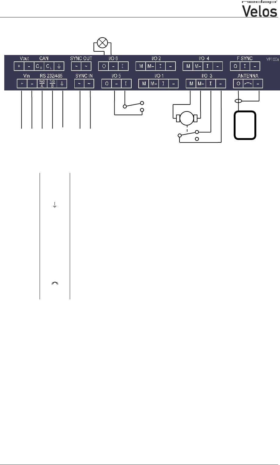
Connections
Figure above : motor, output and input is an example. Configuration is depending on the used
behaviour components. Use display menu and push button to check and configure.
Vin + Power
- Minus
RS232 / 485 RxD / A Data receive
TxD / B Data send
Minus of RS232 / 485
SYNC ~ Synchronisation for HDX, AC (no plus or minus, cable must be twisted pair)
~ See above
I/O 1 .. 4 M Motor output or normal output max 3A
M- Minus for motor output or normal output
I Input of motor or normal input
- Minus for motor input or normal input
I/O 5 .. 6 O Output max 3A
- Minus for output (O) and minus input (I)
I Input
ANTENNA + Antenna with external adjustment (adjustment not on this V-pack)
Antenna with no adjustment, adjustment on this V-pack
- Antenna minus (shield of coax cable)
F SYNC Frequency synchronisation (not used yet)
IMPORTANT : Use fuse 3.15A T between power supply and Vin of the VP1006
M
black
red
green
red
white
brown
VP1006-200PM-00-OEM ISO Reader 4-2007/1.0 Page 4 of 9
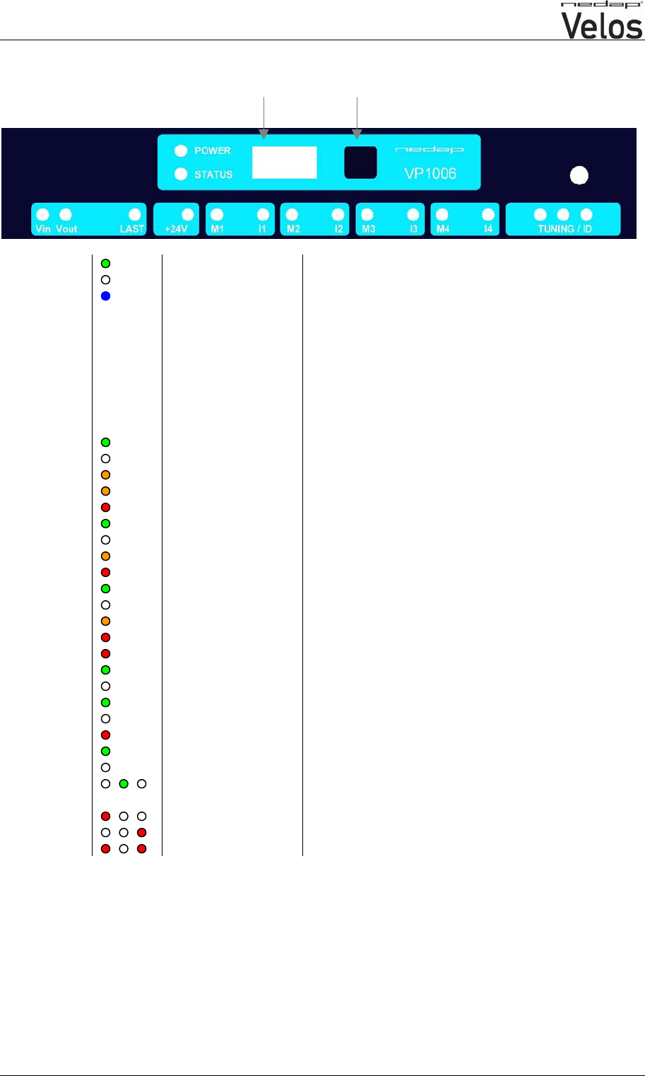
LED indicators VP1006
push button
display
POWER Green on Power on
off No power
STATUS Blue
Slow blinking
Very fast blinking
Fast blinking
1 short flash
2 short flashes
3 short flashes
Operating ok
Service mode activ
Downloading or error during download
V-pack not coupled
Firmware present but not activ
No firmware present
Display on Address indicated No communication
off Communication status ok
V in Green on Power on
off No power
Orange Low power
Orange blinking Wrong power connection, in – out changed
Red Error
V out Green on Power on
off No power
Orange blinking Low power
Red blinking Error
LAST Green on V-pack is last one on the CAN-bus
off Status ok
Orange blinking CAN-bus error and last V-pack on CAN-bus
Red Not used
Red blinking Not used
+24V Green on 24V output switched on
off Output switched off
M1 .. M4 Green on Output on
off Output off
Red blinking Output error
I1 .. I4 Green on Input on
off Input off
TUNING /ID Green on
Green blinking Antenna ok
Antenna ok and tag identified
Red on Antenna out of range
Red on Antenna out of range
Red blinking Antenna error / not connected
VP1006-200PM-00-OEM ISO Reader 4-2007/1.0 Page 5 of 9
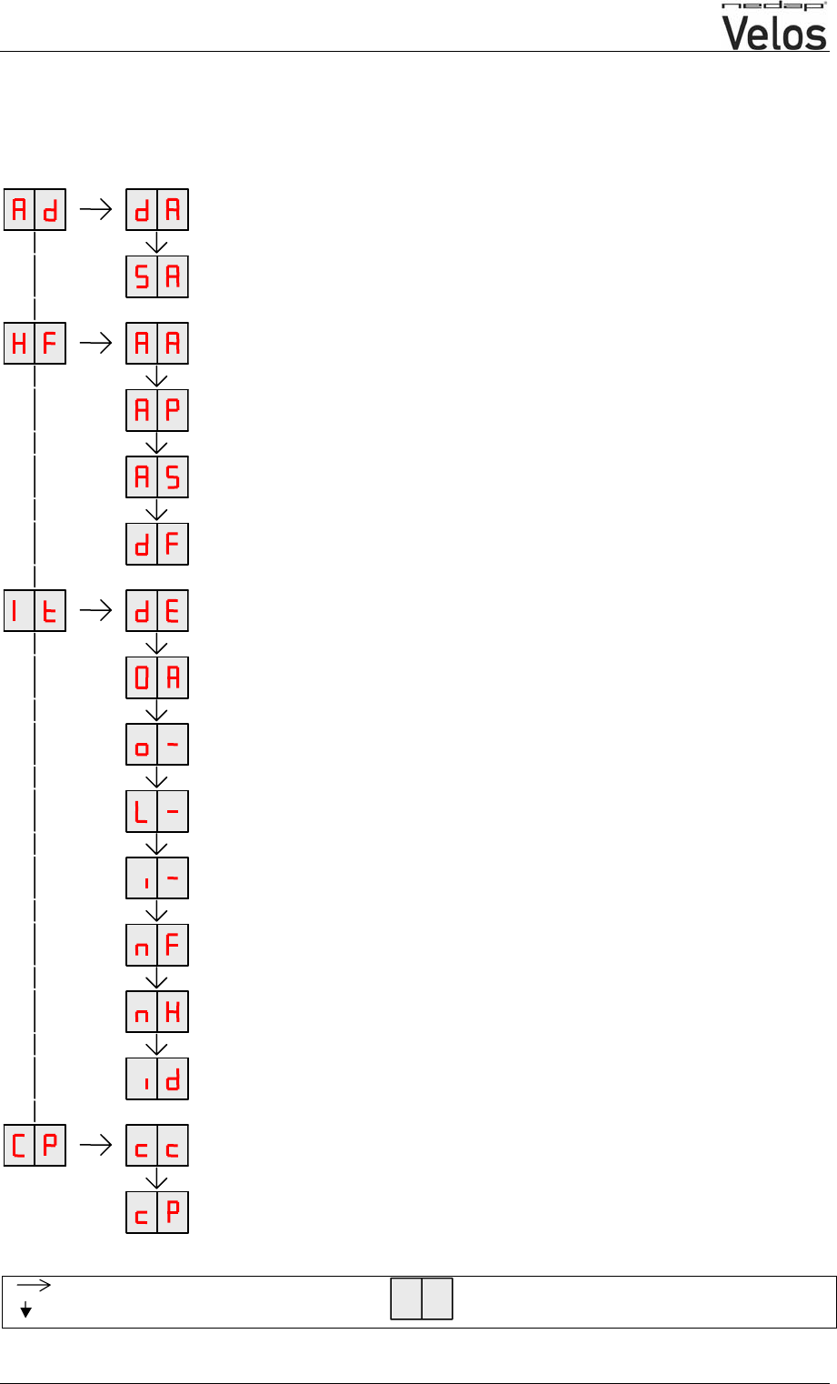
Display menu
DISPLAY ADDRESS
Shows the actual address
SET ADDRESS
Change the address
ADJUST ANTENNA
Antenna tuning will be shown by output 6 (lamp)
ANTENNA POWER
Min/max 10 / 99. Normally set to 99. Possibility to set a lower value.
ANTENNA SENSITIVITY SQUELCH
Min/max 9 / 0. Normally set to 0. Possibility to set a lower value.
SETTINGS TO DEFAULT
All HF settings back to factory settings
DISPLAY ERROR
Shows error code
TEST ALL OUTPUTS
All outputs are switch on one by one. Test results are shown on the display
TEST MOTOR OUTPUT
o1 … o4
TEST OUTPUT
L1 … L6
TEST INPUT
I1 … i6
NOISE LEVEL FDX
Shows noise level measured by the FDX receiver
NOISE LEVEL HDX
Shows noise level measured by the HDX receiver
TEST IDENTIFICATION
Shows last 2 digits of a tag number
COMMUNICATION CHANNEL
Enter a number to set the right settings (see table next page)
COMMUNICATION PROTOCOL
Enter a number to set the right settings (see table next page)
Press button until blinking
Press button short To leave menu:
press button until display is empty
VP1006-200PM-00-OEM ISO Reader 4-2007/1.0 Page 6 of 9
CP-menu communication possibilities
RS232 with Nedap extened protocol
RS232
20
Nedap extened protocol 2400 Baud
21
Nedap extened protocol 9600 Baud 22
Nedap extened protocol 19200 Baud 23
Nedap extened protocol 38400 Baud 24
RS485 with Nedap extened protocol
RS485
Bias off - no. of breaks 0
40
Nedap extened protocol 2400 Baud
21
RS485 Bias on - no. of breaks 0 41 Nedap extened protocol 9600 Baud 22
RS485 Bias off - no. of breaks 2 42 Nedap extened protocol 19200 Baud 23
RS485 Bias on - no. of breaks 2 43 Nedap extened protocol 38400 Baud 24
RS485 Bias off - no. of breaks 4 44
RS485 Bias on - no. of breaks 4 45
RS485 Bias off - no. of breaks 6 46
RS485 Bias on - no. of breaks 6 47
RS485 Bias off - no. of breaks 8 48
RS485 Bias on - no. of breaks 8 49
RS232 with Texas Instruments protocol*
RS232
20
Texas Instruments protocol
10
*Serie 2000 reader systems ASCII protocol, 9600 baud, 8 databits, no parity, 1 stopbit
How to use the display and push button
Scroll down press button short
Select press button until blinking
Change and store select item to change, open item by pressing till blinking, change by pressing
short, store by pressing to blinking
Check a setting select the item to check, press until blinking, first value shown is actual setting
Leave without saving press button untill display blanks
Return to main menu anywhere in the menu, press button untill display blanks
It is possible some program states are shown during operation.

VP1006-200PM-00-OEM ISO Reader 4-2007/1.0 Page 7 of 9
Antenna adjustments
Antenna tuning
After first time power up the antenna tuning must be checked. Check the TUNING led, green is OK
and means the antenna is correctly tuned. When the green led is not ON the antenna must be tuned.
Antenna tuning :
- Turn Lt on the antenna till the green led is ON (use a plastic screw driver)
Green on Antenna tuning ok
Red on Antenna out of range, turn to the right till green led is on
Red on Antenna out of range, turn to the left till green led is on
Red on No antenna connected or low antenna signal
All off Antenna switch off by the software
If there is no antenna led on, software has set the antenna field off, first set the antenna in ID test
mode by using the display/push button.
Antenna power
Default the antenna power is set to maximum (99) and needs no adjustments.
Lowering the antenna power will reduce the reading distance of the antenna.
Check the antenna power
The antenna power level is shown on the display in the service menu at HF option AP (Adjust Power)
- Select menu option AP (Adjust Power) on the display by using the push button next to the display
- Push the button until the display starts to blink, a value will appear on the display
- The value on the display is the actual power setting. 99 is the default factory setting.
- To leave the menu without modifying the settings press the button until the display blanks (press
about 4 seconds)
Modify the antenna power
- Select the actual antenna power on the display (see above check antenna power)
- Press the button shortly, the first value will change
- Press until the desired value, hold now the button until blinking
- The second digit can be changed in the same way
- When the desired value is on the display, press until the display blinks
- The next menu item AS is now indicated.
- To leave the service menu and return to normal operation, press the button until the display blanks
(press about 4 seconds)

VP1006-200PM-00-OEM ISO Reader 4-2007/1.0 Page 8 of 9
Antenna squelch
Antenna squelch is a possibility to set a threshold for the ID level of a tag. It means the antenna
power is still the same, but the software will not transfer weak received tag numbers.
Default the antenna squelch is set to minimum (-0). This means no threshold. Maximum is -9.
Check the antenna squelch level
The antenna squelch level is shown on the display in the service menu at HF, option AS (Adjust
Squelch)
- Select menu option AS (Adjust Squelch) on the display by using the push button next to the display
- Push the button until the display starts to blink, a value will appear on the display
- The value on the display is the actual power setting. -0 is the default factory setting.
- To leave the menu without modifying the settings press the button until the display blanks (press
about 4 seconds)
Modify the antenna squelch level
- Select the actual antenna squelch level on the display (see above check squelch level)
- Press the button shortly, the value will change
- Press until the desired value, hold now the button until blinking
- The next menu item “df” is now indicated.
- To leave the service menu and return to normal operation, press the button until the display blanks
(press about 4 seconds)

VP1006-200PM-00-OEM ISO Reader 4-2007/1.0 Page 9 of 9
Firm ware
A VP1006 is equipped with software to run in- and outputs, display / push button and a motor
safeguard. This software is during production of the VP1006 already build-in. In case of an update it is
possible to download new software thru the CAN-bus.
Specifications VP 1006 (art.no. 9915834)
Dimensions 143 x 120 x 68 mm LxWxH (excluding mounting rail) Weight: ± 360 gr
CAN CAN-bus communication 125 kBit
Power Input voltage 25 VDC, +20% -20%
Minimal power consumption 300 mA with antenna switched on
Maximum power consumption 2,5 A
Protected against reverse connection power supply
Software Downloadable thru network
Inputs Reading inputs, analog (0-40V) and digital.
Suitable for NPN and PNP sensors.
Outputs Max. 2.5 Amp by current limiter, short-circuiting protected
Motor safe-guard (after 25 sec)
Antennas Different types possible
Detection distance Varies per antenna
Synchronisation Synchronisation according to ISO 11785
Environment Temperature: Operating: -10 – 55 °C, Storage: -25 – 70 °C
Relative humidity: 10 – 93% non condensing
IP class IP 30. When installed in V-box IP 65 (cover and cables installed correctly !)
Cable specifications
CAN-bus Power min. 1.0 mm2
CAN min. 0.34 mm2 twisted pair.
Antenna Coax RG58. Max. length depending on antenna type.
Outputs CE approved at cable length < 3m
Inputs CE approved at cable length < 3m
Synchronisation Twisted pair minimum 2x0.24mm2. Total max. 500m
Always use a NEDAP power supply
The Nedap guarantee-regulations are only valid when is installed as indicated in this manual.
Install data cables at a safe distance from (high) powered cables
More information
For more detailed information contact your local Nedap supplier or check the internet site.
VP6001-200PM-00 V-sense 4-2007/0.1
VP6001
V-sense antenna
This information is furnished for guidance, and with no guarantee as to its accuracy or completeness; its publication conveys no
licence under any patent or other right, nor does the publisher assume liability for any consequence of its use; specifications and
availability of goods mentioned in it are subject to change without notice; it is not to be reproduced in any way, in whole or in
part, without the written consent of the publisher.
© Nedap N.V., AGRI P.O. Box 104 NL-7140 AC GROENLO The Netherlands
VP2001-200PM-00 Power supply 4-2007/0.1 Page 2 of 2
VP6001
V-sense antenna
General
The VP6001 is used as antenna in Velos system and connected to a V-pack with identification.
This device complies with Part 15 of the FCC Rules. Operation is subject to the following two
conditions: (1) this device may not cause harmful interference, and (2) this device must accept
any interference received, including interference that may cause undesired operation.
Connections
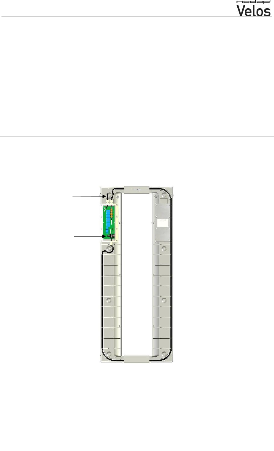
The VP6001 is connected to a V-pack by a coax cable, see manual of the concerning V-pack.
To open the VP6001 : remove screws at the side.
Adjustment
Tuning must be done by Lt with a plastic screw driver.
See manual of the connected V-pack for tuning instructions.
Lt
To antenna of V-pack