Nedap N V VELOS5 Inductive Proximity Card Reader User Manual 5277434 Quick start VP1004 1 1
N. V. Nederlandsche Apparatenfabriek NEDAP Inductive Proximity Card Reader 5277434 Quick start VP1004 1 1
User manual
VP
1004
-
ISO
Reader
Multiplexer
-
Quick start
9-
2011
Doc.part.
no. 5277434
45
.01
B 1/ 4
Quick start
VP
1004
ISO
Reader
Multiplexer
The Velos VP
100
4
is a Velos component t
hat is used to identify animals
.
The VP
100
4
must be
installed in a V
-
box.
A VP
1004
is connected to the Velos CAN
-
bus and controlled by a
VP8001 (
VPU
).
Inputs / Outputs
/ Antennas
- 8
antennas,
auto scanning one by one
(max 10x VP1004 per VP
8001)
- 2
outputs available to act
ivate e.g. lights and 2 inputs for reading e.g.
switches
FCC ID: CGDVELOS5 and IC: 1444A
-
VELOS5
Compliance statement (pa
rt15.19)
This device complies with part 15 of the FCC Rules and to RSS210 of Industry Canada.
Operation is subject to the following two conditions:
(1) this device may not cause harmful interference, and
(2) this device must accept any interference receive
d, including interference that may cause undesired operation.
Déclaration Conformité
Cet appareil se conforme aux normes RSS210 exemptés de license du Industry Canada. L'opération est soumis aux deux
conditions suivantes:
(1) cet appareil ne doit causer au
cune interférence, et
(2) cet appareil doit accepter n'importe quelle interférence, y inclus interférence qui peut causer une opération non pas vou
lu
de cet appareil.
Warning (part15.21)
Changes or modifications not expressly approved by party responsibl
e for compliance could void the user s authority to operate
the equipment.
This in particular is applicable for the antenna which can be delivered with the VP4001 System.
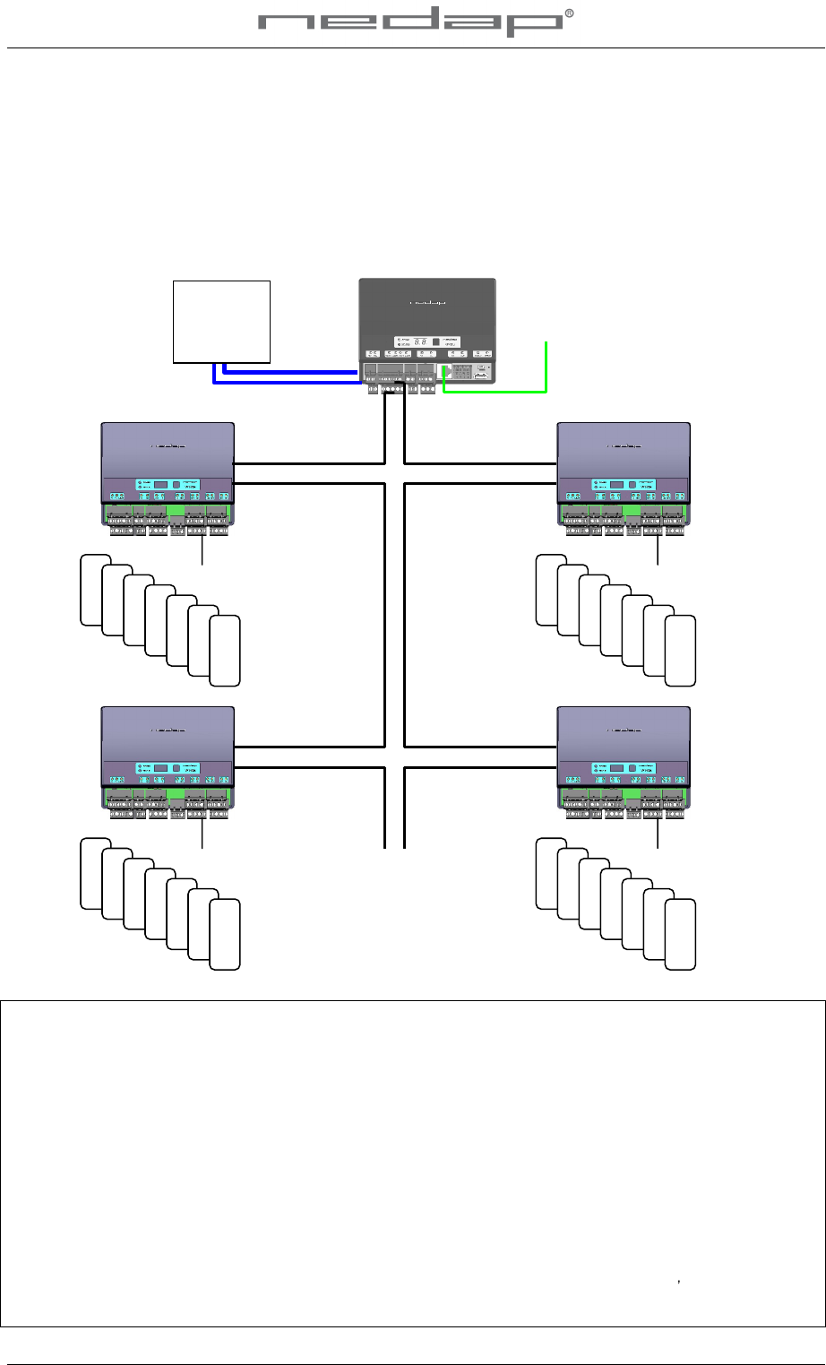
V
P8001
To PC (LAN ethernet)
Po
wer
Supply
VP2001
max 3m
V
P1004
Antenna 1
-
8
Next VP1004
V
P1004
Next VP1004
Antenna 17
-
24
V
P1004
Antenna 9
-
16
V
P1004
Antenna 25
-
32
VP
1004
-
ISO
Reader
Multiplexer
-
Quick start
9-
2011
Doc.part.
no. 5277434
45
.01
B 2/ 4
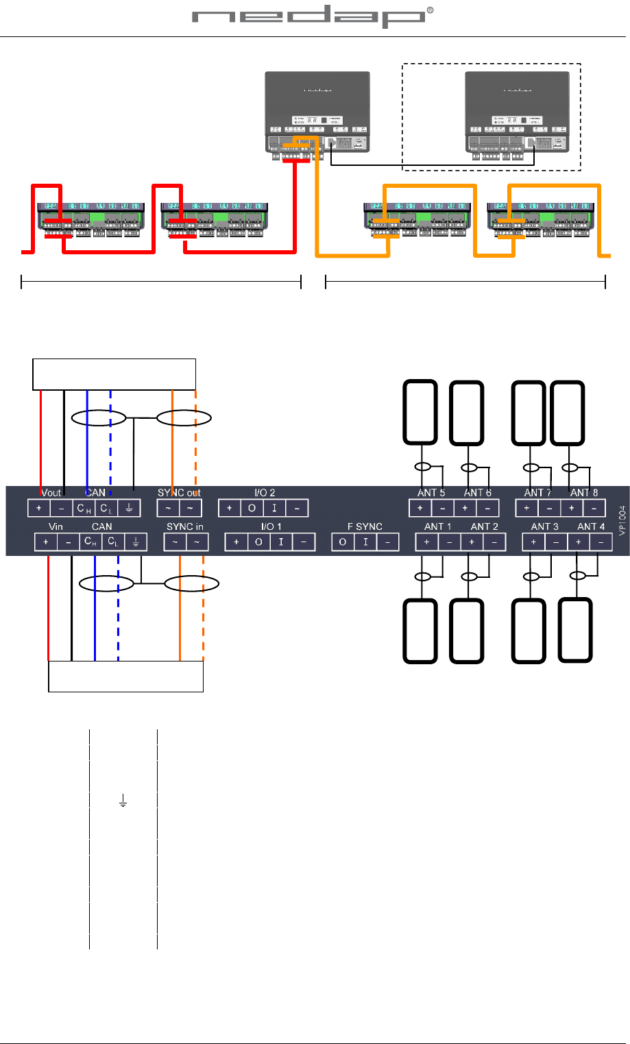
Connections
Details VP
1004
inputs and outputs
Vin
+
Input voltage 24 VDC, +20%
-
20%
-
Minus
CAN
C
H
CAN high (cable twisted pair with C
L
)
C
L
CAN low (cable twisted pair with C
H
)
Shielding of CAN
-
bus cable
SYNC
~
Synchronisation
(no plus or minus, cable must be twisted pair)
~
See above
I/O 1 ..
2 +
Output max 400
mA
O
Output max 400
mA
/ 1.7A input
-
Minus for
output (O
) and
minus
input (I)
I
Input
ANTENNA
+
Antenn
a
(core)
-
Antenn
a (shield of coax cable)
F SYNC
FI/F
O
Frequency synchronisation FI=in FO=out
VP1004
VP1004
VP1004
V
P8001
(1)
V
P8001
(2)
VP1004
LAN
o
range
blue white
blue
black
red
orange white
Velos cable
IN
Velos cable
OUT
(
to next VP1004)
antenna
o
range
blue white
blue
black
red
orange white
Velos cable
Lmax = 80m Max =
5
x VP1004
Velos cable Lmax = 80m M
ax = 5x VP1004
VP
1004
-
ISO
Reader
Multiplexer
-
Quick start
9-
2011
Doc.part.
no. 5277434
45
.01
B 3/ 4
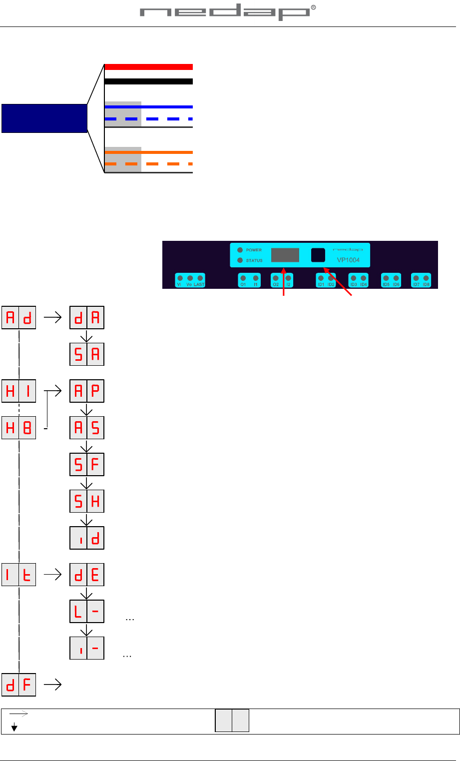
Details Velos cable
Antennas
A VP1004
has an automatic tuning module. The status is shown with LED indicators.
Only
V-
sense antennas
types can be used
.
Not all types are compati
ble, check compatibility before
use.
Display menu
display
push button
DISPLAY
ADDRESS
Shows the actual address
SET ADDRESS
Change the address
ANTENNA
POWER
Min/max 10 / 99. Normally set to 99. Possible to set a lower value.
ANTENNA
SENSITIVITY SQUELCH
Min/max 9 / 0. Normally set to 0. Poss
ible to set a lower value.
SIGNAL LEVEL FDX
Shows signal level measured by the FDX receiver
SIGNAL LEVEL HDX
Shows signal level measured by the HDX receiver
TEST IDENTIFICATION
Shows last 2 digits of a tag number
DISPLAY ERROR
Shows error code
TEST OUTPUT
L1 L5
TEST INPUT
I1 i5
SETTINGS TO DEFAULT
All HF settings back to factory settings
(enter 99)
Press button until blinking
Press button short
To leave menu:
press button until display is empty
Red (+)
Black (
-)
Blue (C
h)
Blue/white (C
l)
Shield
Orange (Sync)
Orange/white (Sync)
Shield
Power
1,5 mm
2
Communication
0,34 mm
2
Twisted pair shielded
HF Synchronisation
0,34 mm
2
Twisted pair shielded
Part No. 7705310
VP
1004
-
ISO
Reader
Multiplexer
-
Quick start
9-
2011
Doc.part.
no. 5277434
45
.01
B 4/ 4
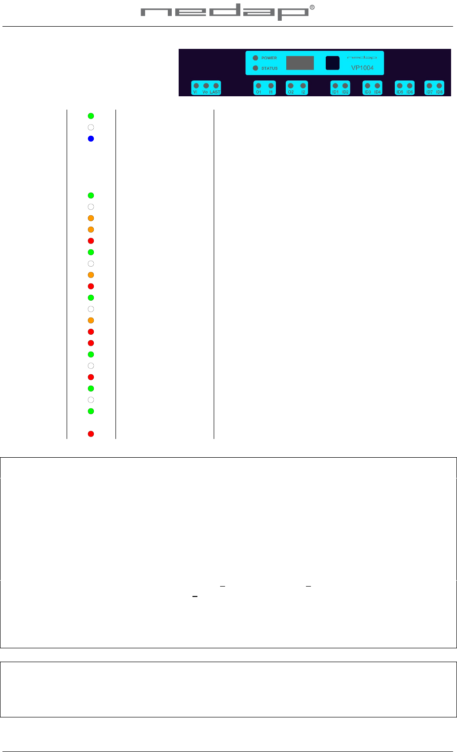
LED indicators
POWER
Green on
Power on
off
No power
STATUS
Blue
Slow breathing
Fast blinkin
g
Operating ok
Downloading or error during download
Display
on
Address indicated
No communication
off
Communication status ok
V in
Green on
Input power applied
off
No power
Orange
Low power, lower then 20V
Orange blinking
Wrong CAN
-
bus connection, Vin and Vout swapped
Red
Error, plus and minus swapped
V out
Green on
Output power
off
No power
Orange blinking
Low power
Red blinking
Error, plus and minus swapped
LAST
Green on
V-
pack is last one on the CAN
-
bus
off
V-
pack is not last one on the CAN
-
bus
Orange blinking
CAN
-
bus error and last V
-
pack on CAN
-
bus
Red
CAN
-
bus error
Red blinking
CAN
-
bus warning / wrong connected
O1 .. O
2
Green on
Output on
off
Output off
Red blinking
Output error
/ ove
rload
I1 .. I
2
Green on
Input contact open
off
Input contact closed
ID
Green one by one
Green on
Antenna ok
Antenna ok and tag identified
Red on
Antenna
error / not connected /
not tuned correctly
Specifications VP 1004
Dimensions
143 x 120 x 68 mm LxWxH (excluding mounting rail) Weight: ± 360 gr
CAN
CAN
-
bus communication
125 kBit
Power
Input voltage 25 VDC, +20%
-
20%
Min power consumption 300 mA with antenna switched on
Protected against reverse connection power supply
Software
Downloadable by the CAN network
Inputs
Reading inputs, analog (0
-
40V) and digital. Suitable for NPN and PNP sensors.
Outputs
Max. 0.4 Amp by
current limiter, short
-
circuiting protected
Antennas
800 µH. Different types possible.
Detection distance
Varies per antenna
Synchronization
Synchronization according to ISO 11785
/ 24631
-6
Environment
Temperature: Operating:
-
10
55 °C, Storage: -
25
70 °C
Relative humidity: 10
93% non condensing
IP class
IP 30. When installed in V
-
box IP 65
(cover and cables installed correctly !)
Always use a NEDAP power supply. The Nedap guarantee
-regulations are only valid when is installed as
indicated in
this manual. I
nstall data cables at a safe distance from (high) powered cables
For more detailed information contact your local Nedap supplier or check the internet site.
This information is furnished for guidance, and with no guarantee as to its accura
cy or completeness; its publication conveys no
licence under any patent or other right, nor does the publisher assume liability for any consequence of its use; specificatio
ns and
availability of goods mentioned in it are subject to change without notice; i
t is not to be reproduced in any way, in whole or in
part, without the written consent of the publisher.
© Nedap N.V., AGRI P.O. Box 104 NL
-
7140 AC GROENLO The Netherlands