Nedap N V VP1801 RFID system User Manual Product name
N. V. Nederlandsche Apparatenfabriek NEDAP RFID system Product name
Manual
Doc. part. no. 5278724 / Manual version 1.0 / 08-2016
EN
Quick start manual
VP1801 Reader Motor Control
This sheet is only intended as quick start. See service manual for detailed instructions.
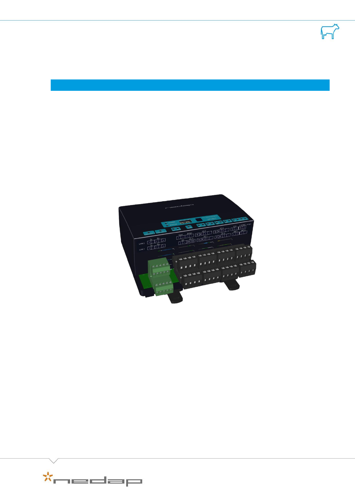
The VP1801 is a Velos component that is used to identify animals for feeding, weighing, milking,
heat detection etc. The VP1801 is equipped with an internal switch to support a double Ethernet
connection (web interface ready) and the existing VC3 interface. The Ethernet channel is used
for the main functionality and communication like software updates and service. An extra
communication channel is available for the VC3 systems. The function is the same as the existing
Single Feeder.
The VP1801 can be installed in a V-box.
Quick start manual | VP1801 Reader Motor Control
2
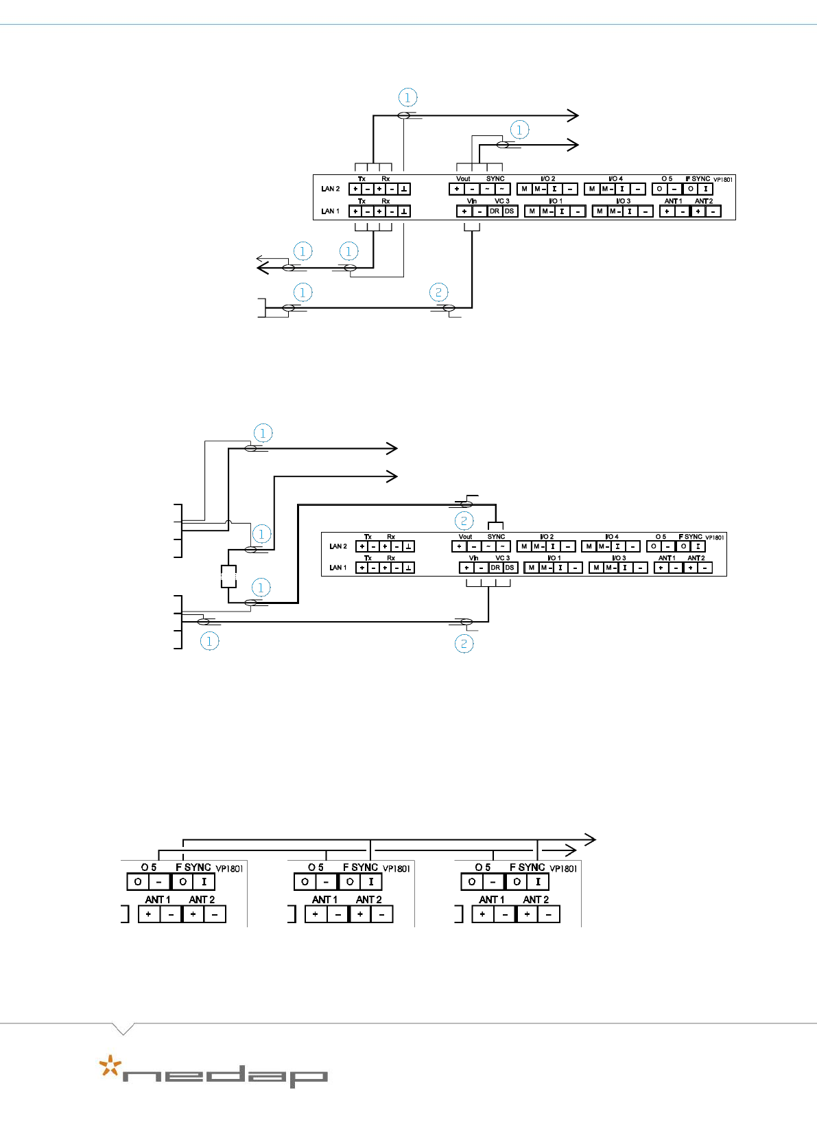
A VP1801 can be connected in different ways:
To a shielded Ethernet cable and controlled by a switch or VPU:
When connecting the Ethernet cable, the VP1801 automatically detects TX/RX , plus and minus
connections, and switches to the correct connection.
To a shielded four wire cable and controlled by a VC3 host:
The SYNC connection is necessary for HDX ISO synchronization between other readers. For FDX
a SYNC connection is possible, but not necessary if only one antenna is used. When two
antennas are used the SYNC connection is always needed, even when FDX-only (no ISO) mode is
enabled. The switching between the two antennas uses the ISO timing.
The F SYNC connection is necessary when the distance between two antennas is ≤ 3 m. Connect
the F SYNC as shown in the picture below.
+
-
1. Shielded cable
2. Shielded cable,
shield not connected
to VP1801.
LAN next VP1801
Power
supply
VC3 next VP1801
+
-
DR
DS
+
-
DR
DS
VC3
interface
bridge
Vin next VP1801
SYNC next VP1801
1. Shielded cable
2. Shielded cable,
shield not connected
to VP1801.
Switch
VPU
F SYNC I next VP1801
O5 minus next VP1801

Doc. part. no. 5278724 / Manual version 1.0 / 08-2016
3
Installation steps Ethernet
Step 1
Install the VP1801 in the V-box (or other box). See the manual of the relevant
equipment (feeding station, separation unit etc.) where is indicated how to install
the V-box.
Step 2
Connect all required wiring. See the manual of the relevant equipment and the
manual of the required behaviour component.
Step 3
Power up and check the LED indicators, see also the overview on page 9.
Step 4
When the system is equipped with the auto-addressing function, the host
computer requires the address. Select “Sp > y” in the display menu of the VP1801,
see page 6. Go to Step 8.
Step 5
When auto-addressing is not available, set the required address manually via “Ad”
in the display menu, see page 6.
Step 6
Check the ip settings via “IP” in the display menu, see page 6. Default DHCP is on.
When DHCP must be switched off, set the required ip address settings via “IP” in
the display menu. When DHCP is switched off, the default IP address is
192.168.1.100.
Step 7
Check the antenna tuning. Select “HF > H1 > tu” in the display menu to start and
enable autotune, see page 7. If external manual adjustment is used (e.g. adjustable
antenna-trafo), select “AA” in the display menu, see page 7.
Step 8
Test the functioning. See manual of the behaviour component. In case of
malfunctioning the connected devices like sensors, motors, valves can be checked
with options from menu option “It”, see page 7.
Installation steps VC3
Step 1
Install the VP1801 in the V-box (or other box). See the manual of the relevant
equipment (feeder, separation unit etc.) where is indicated how to install the V-
box.
Step 2
Connect all required wiring. See the manual of the relevant VC3 application.
Step 3
Power up and check the LED indicators, see also overview on page 9.
Step 4
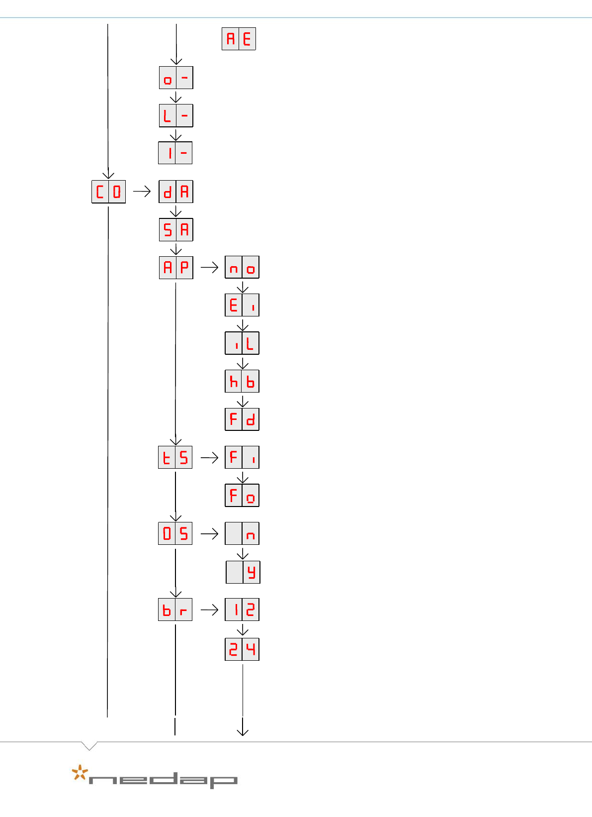
Set the required VC3 address via “CO > SA” in the display menu, see page 8.
Step 5
Select the VC3 application and other relevant VC3 settings via “CO > AP”, see page
8.
Step 5
Check the antenna tuning. Select “HF > H1 > tu” in the display menu to start and
enable autotune, see page 7. If external manual adjustment is used (e.g. adjustable
antenna-trafo), select “AA” in the display menu, see page 7.
Step 6
Test the functioning. See the manual of the VC3 application. In case of
malfunctioning of the connected devices like sensors, motors, valves execute a
test with options from menu option “It”, see page 7.

Quick start manual | VP1801 Reader Motor Control
4
Connections
See the manual of the concerning behaviour component for a detailed overview of the
connections. O5 is default controlled by the identification process of the VP1801 itself, and can
be overruled by the behaviour component. If the V-box has a signal light, connect it default to
O5.
When connecting the Ethernet cable, the VP1801 automatically detects TX/RX , plus and minus
connections, and switches to the correct connection.
Details VP1801 inputs and outputs
LAN
Tx +
Transmit (shielded CAT5E FTP (Foiled Twister Pair, also called S/UTP)
stranded AWG26 or AWG24 (preferred)). Cable length max. 100 m.
Tx -
Transmit
Rx +
Receive
Rx -
Receive
Ethernet shielding
Vin
+
Input voltage 25 VDC, +20% -20%
-
Minus
Vout
+
Output (max 4A)
-
Minus
VC3
DR
VC3 data receive. Shielded cable, cable length max. 40 m.
DS
VC3 data send
SYNC
~
Synchronisation for HDX or 2 installed antennas, AC (no plus or minus,
cable must be shielded twisted pair). Max. 20 devices parallel, total
cable length max. 300 m.
~
See above
I/O 1 .. 4
M
Motor output or normal output max 3.5A as total current for the 4
outputs. Cable length max. 3 m.
M-
Minus for motor output or normal output
I
Input of motor or normal input
-
Minus for motor input or normal input
O5
O
Output max 400mA continue. Cable length max. 3 m.
-
Minus for output (O) and minus input (I)
ANT 1
+
Antenna 1 (core of coax). Cable length max. 10 m.
-
Minus for antenna 1 (shield of coax)
ANT 2
+
Antenna 2 (core of coax). Cable length max. 10 m.
-
Minus for antenna 2 (shield of coax)
F SYNC
O
Output for FDX synchronization of the antenna signal phase (core of
coax: shield connected with minus of O5). Cable length max. 3 m.
I
Input for synchronization of antenna signal phase (core of coax: shield
connected with minus of O5). Cable length max. 3 m.

Doc. part. no. 5278724 / Manual version 1.0 / 08-2016
5
Antennas
The VP1801 has two antenna connections and one internal reader. When two antennas are
connected, the used application determines if the second antenna is used or not. In case the
reader has to control both antennas, the reader switches fast between the two antennas in a
smart way. That means the identification time is divided over the two antennas with a switching
time that can vary between 24ms and 120ms in case both antennas have the same priority.
Priority is controlled by Ethernet control like a behaviour component.
Autotune
The VP1801 is equipped with the autotune function. This means it can tune an antenna by itself
due to an integrated internal tuning-circuit on board. Tuning can be started with the display
menu “HF > H1 > tu”, remote from an external command over Ethernet or with the web-interface
of the VP1801.
Important!
Autotune works with all Nedap antennas. In case external antenna adjustment is used
(e.g. adjustable antenna-trafo), the autotune function must be switched off to achieve
the maximum reading distance. This can be done via “HF > HI > AA” in the menu
display of the VP1801, see page 6. Then the autotune function is disabled until it is
started again with the display menu “HF > H1 > tu”.
Quick start manual | VP1801 Reader Motor Control
6
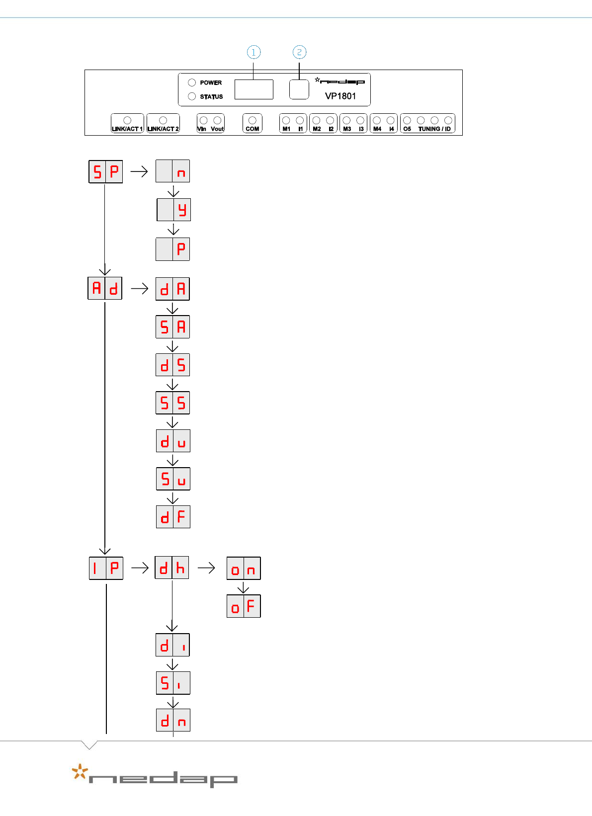
Display menu
SERIAL NUMBER
Shows last four digits of serial number
SYSTEM PING
Send system ping
PROGRAM VERSION
Shows program version
DISPLAY ADDRESS
Shows the actual address
SET ADDRESS
Change the address
DISPLAY SECTION
Show section (Default 0, enter 0 to have access to IP address settings)
SET SECTION
Change section
DISPLAY VPU UNIT ADDRESS
Shows actual VPU unit address ( Default 0)
SET VPU UNIT ADDRESS
Changes the actual unit VPU unit address
SETTINGS TO DEFAULT
All address settings back to factory settings
DHCP IS ON
Press long until blinking to turn on DHCP
DHCP IS OFF
Press long until blinking to turn off DHCP
DISPLAY IP ADDRESS
Shows actual IP address (one by one)
SET IP ADDRESS
DISPLAY NETWORK MASK (only shown in case of DHCP OFF)
Shows network mask (8=255.0.0.0, 16=255.255.0.0, 24=255.255.255.0)
1. Display
2. Push button
Doc. part. no. 5278724 / Manual version 1.0 / 08-2016
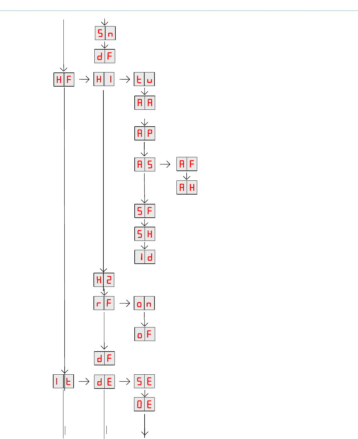
7
AUTOTUNE MODE
Starts antenna tuning
ADJUST ANTENNA
Antenna tuning level will be shown (sets autotuning
position off)
ANTENNA POWER
Min/max 10 / 99. Normally set to 25 (=25% of maximum
power).
ANTENNA SENSITIVITY SQUELCH FDX
Set squelch level FDX
ANTENNA SENSITIVITY SQUELCH HDX
Set squelch level HDX
SIGNAL LEVEL FDX
Shows signal level measured by the FDX receiver
SIGNAL LEVEL HDX
Shows signal level measured by the HDX receiver
TEST IDENTIFICATION
Shows last 2 digits of a tag number
SEE H1 MENU
RESPONDER NUMBER FILTER ON
Accepts only 999 or 984 country code responder numbers
(Nedap)
RESPONDER NUMBER FILTER OFF
Reads all responder numbers
SETTINGS TO DEFAULT
All antenna settings to default
DISPLAY ERROR
Safeguard error
DISPLAY ERROR
Output error
SET NETWORK MASK (only shown in case of DHCP OFF)
Changes network mask (8=255.0.0.0, 16=255.255.0.0, 24=255.255.255.0)
SETTINGS TO DEFAULT
All address settings back to factory settings
Quick start manual | VP1801 Reader Motor Control
8
DISPLAY ERROR
Other system errors
TEST MOTOR 1-4
M1…M4
TEST OUTPUT 1-5
L1…L5
TEST INPUT 1-4
I1…I4
VC3 DISPLAY ADDRESS
Shows the actual address
VC3 SET ADDRESS
Change the address
NO VC3 APPLICATION
Select no VC3 application
ETHERNET IDENTIFICATION
ILS PROGRAM
Select Identification Lon Standard
WHS PROGRAM
Select Walk through herringbone or side-by-side
FSS PROGRAM
Select Feed Station
TAG READER SETTING FULL ISO
Select Full ISO tag
TAG READER FDX ONLY
Select FDX only no-ISOtag
2 HOURS DATA
Do not send 2 hours data over VC3 channel
2 HOURS DATA
Send 2 hours data over VC3 channel
VC3 COMMUNICATION SPEED 1200 BAUD
Set communication speed to 1200 Baud
VC3 COMMUNICATION SPEED 2400 BAUD
Set communication speed to 2400 Baud
Doc. part. no. 5278724 / Manual version 1.0 / 08-2016
9
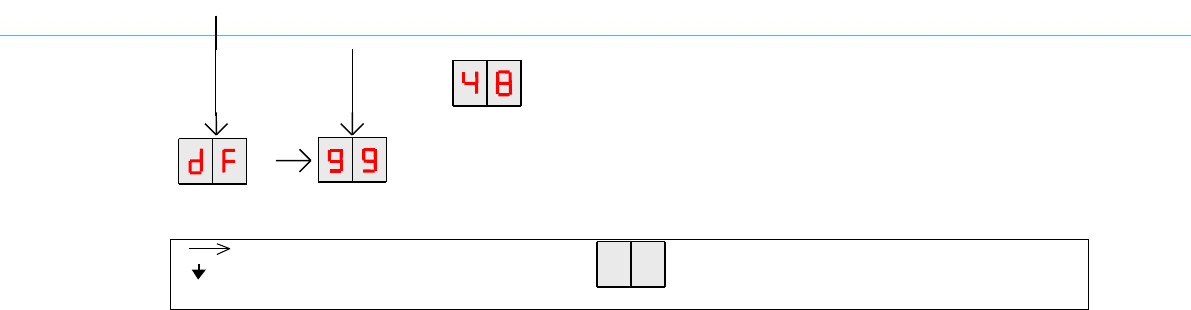
VC3 COMMUNICATION SPEED 4800 BAUD
Set communication speed to 4800 Baud
DEFAULT
Enter value 99 to return to factory defaults
Press button until blinking
Press button short
To leave menu:
press button until display is empty
How to use the display and push button
Activate the menu press short on the button, the display menu is shown
Scroll down press short
Select press until blinking
Change and store select item to change, open item by pressing till blinking, change by
pressing short, store by pressing to blinking
Check a setting select the item to check, press until blinking, first value shown is actual
setting
Quick start manual | VP1801 Reader Motor Control
10
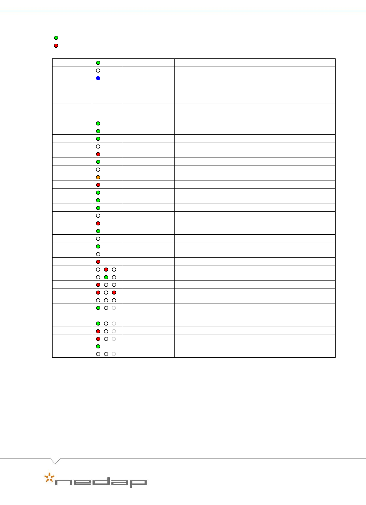
LED indicators
= OK
= not OK
POWER
Green on
Power on
off
No power
STATUS
Slow blinking
Fast blinking
Short blinking
Long blinking
Operating ok
Downloading or error during download
Not connected to the host
Connection established to the host
Display
on
Address indicated
No communication
off
Communication status ok
LINK/ACT
Green on
Connection ok
Green blinking
Data transmit
V in
Green on
Input power applied
Off
No power
Red
Error, plus and minus swapped
V out
Green on
Output power
off
No power
Orange blinking
Low power
Red blinking
Error, plus and minus swapped
COM
Green on
Connection VC3 channel
Green blinking
Data transmit VC3 channel
M1…M4
Green on
Output on
Off
Output off
Red blinking
Output error
I1….I4
Green on
Input contact closed
Off
Input contact open
O5
Green on
Output on
Off
Output off
Red blinking
Output error
Tuning/ID
Red blinking
Tuning
One antenna
Green on
Antenna tuning ok
Red on
Antenna not tuned
Red blinking
No antenna connected or low antenna signal
Off
Antenna off
Two
antennas
Green on
Antenna 1 tuning ok
Green blinking
Antenna 1 tag identified
Red on
Antenna 1 not tuned
Red/green
blinking
Antenna 1 tag identified + not tuned
Off
Antenna 1 off
The described LED indicators apply to antenna 1 (left LED indicator). The same indicators are
used for antenna 2 (right LED indicator).

Doc. part. no. 5278724 / Manual version 1.0 / 08-2016
11
Specifications VP 1801
Dimensions
143 x 120 x 68 mm LxWxH (excluding mounting rail) Weight: ± 430 gr
Power
Input voltage 25 VDC, +20% -20%
Max current consumption without connected I/O = 300 mA
Maximum (total) motor output current 3,5 A
Protected against reverse connection power supply
Software
Check for available updates
Inputs I1 – I4
0V – 35V DC
Suitable for NPN sensors
Outputs O1 – O4
In total max. 3.5 Amp continue, short-circuiting and overload protected
O5
Max. 400mA continue, short-circuiting and overload protected
V out
Max. 4A continue, short-circuiting and overload protected
Synchronization
Synchronization according to ISO 11785
Environment
Temperature: Operating: -10 – 50 °C, Storage: -25 – 50 °C
Relative humidity: 10 – 93% non condensing
Maximum noise level: 10 dBµA/m quasi peak, according CISPR 16-1-1
Conducted noise: according EN55022
IP class
IP 30. When installed in V-box IP 65 (cover and cables installed correctly !)
Always use a NEDAP power supply. The Nedap guarantee-regulations are only valid when is installed as indicated in this manual. Install data cables at
a safe distance from (high) powered cables. For more detailed information contact your local Nedap supplier or check the internet site.
Declaration of Conformity

Quick start manual | VP1801 Reader Motor Control
12
FCC ID : CGDVP1801
IC : 1444A-VP1801
FCC and IC Compliance statement
This device complies with part 15 of the FCC Rules and to RSS210 of Industry Canada. Operation is subject to the following two
conditions:
(1) this device may not cause harmful interference, and
(2) this device must accept any interference received, including interference that may cause undesired operation.
Changes or modifications not expressly approved by the party responsible for compliance could void the
user’s authority to operate the equipment.
Cet appareil se conforme aux normes RSS 210 exemptés de license du Industry Canada. L’opération est soumis aux deux
conditions suivantes:
(1) cet appareil ne doit causer aucune interférence, et
(2) cet appareil doit accepter n’importe quelle interférence, y inclus interférence qui peut causer une opération non pas voulu
de cet appareil.
Les changements ou modifications n’ayant pas été expressément approuvés par la partie responsable de la conformité
peuvent faire perdre à l’utilisateur l’autorisation de faire fonctionner le matériel.
FCC and ISED Radiation Exposure Statement
This equipment complies with FCC and Canadian radiation exposure limits set forth in RSS-102 for a controlled environment.
This equipment should be installed and operated with a minimum distance of 20 cm between the radiator and your body. This
transmitter must not be co-located or operating in conjunction with any other antenna or transmitter.
Cet équipement est conforme a RSS-102 limites énoncées pour un environne- ment non contrôlé. Cet équipement doit être
installé et utilisé avec une distance minimale de 20 cm entre le radiateur et votre corps.
ISED EMC Declaration
This Class B digital apparatus complies with Canadian ICES-003.
Cet appareil numérique de Classe B est conforme à la norme Canadienne ICES-003.
FCC Information to the user
Note: This equipment has been tested and found to comply with the limits for a class B digital devices, pursuant to part 15 of
the FCC Rules. These limits are designed to provide reasonable protection against harmful interference in a residential
installation. This equipment generates, uses and can radiate radio
frequent energy and, if not installed and used in accordance with the instructions, may cause harmful interference to radio
communications.
However, there is no guarantee that interference will not occur in a particular installation. If this equipment does not cause
harmful interference to radio or television reception, which can be determine by turning the equipment off and on, the user is
encouraged to try to correct the interference by one or more of the following measures:
Reorient or relocate the receiving antenna.
Increase the separation between the equipment and receiver.
Connect the equipment into an outlet on a circuit different from that to which the receiver.
Any changes or modifications not expressly approved by the party responsible for compliance could void the user's
authority to operate the equipment.
To ensure compliance with FCC regulations, use only the shielded interface cables provided with the product, or
additional specified components or accessories that can be used with the installation of the product.
This information is furnished for guidance, and with no guarantee as to its accuracy or completeness; its publication conveys no licence under
any patent or other right, nor does the publisher assume liability for any consequence of its use; specifications and availability of goods
mentioned in it are subject to change without notice; it is not to be reproduced in any way, in whole or in part, without the written consent of the
publisher.
© Nedap N.V., Livestock management P.O. Box 104 NL-7140 AC GROENLO The Netherlands.