Nedap N V VP1910 Inductive Card Reader User Manual
N. V. Nederlandsche Apparatenfabriek NEDAP Inductive Card Reader
UserManual.wiki
>
Nedap N V
>
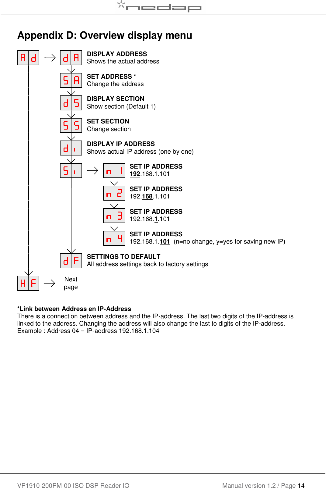
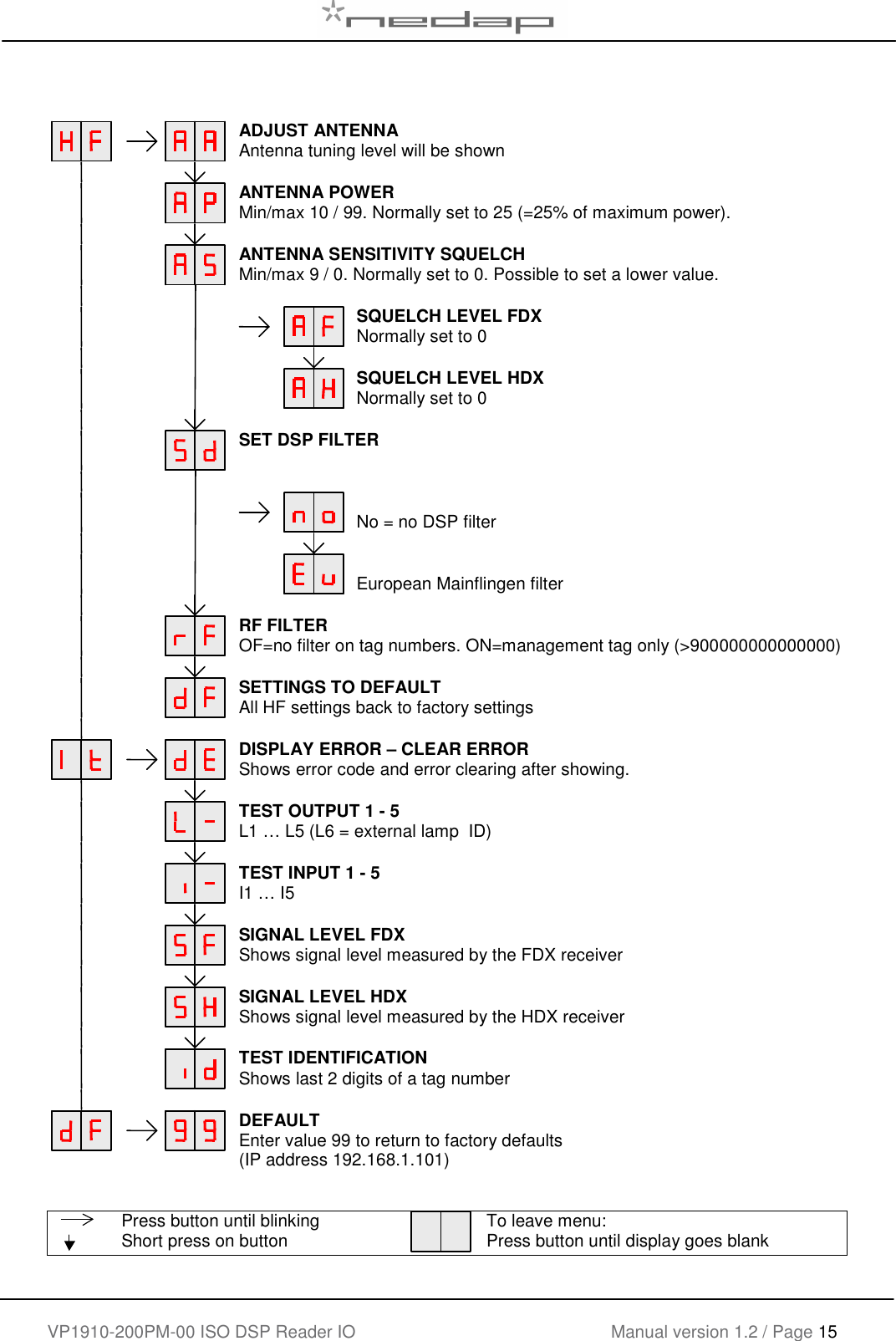
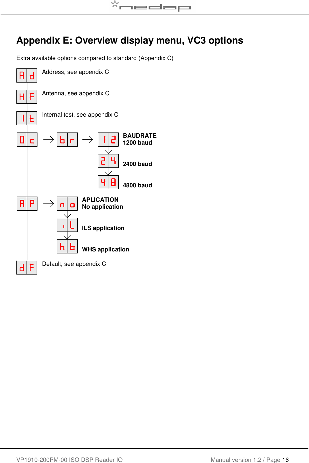
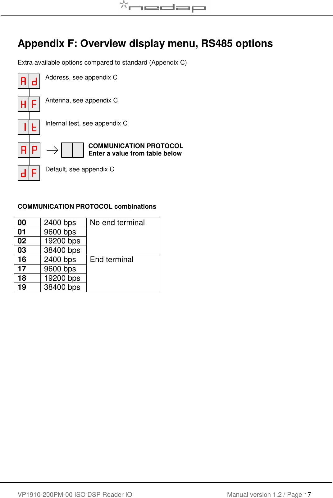
VP1910 User Manual
User Manual
Navigation menu
Upload a User Manual
Namespaces
Wiki Guide
HTML
PDF
Info
Views
User Manual
Discussion / Help
Navigation