Nedap N V VP1910 Inductive Card Reader User Manual
N. V. Nederlandsche Apparatenfabriek NEDAP Inductive Card Reader
User Manual
Service manual
For installation, operation and service
ISO DSP Reader IO
.
VP1910
9 - 2012 / Manual version 1.2
Manual part no. 5278503

VP1910-200PM-00 ISO DSP Reader Manual version 1.2
Version overview
Manual version 1
.0 /
10
-
2011
First release
Manual version 1.1 / 12
-
2011
New menu options described and appendixes added.
Manual version 1.2 / 9
-
2012
FCC and industry Canada text added. Max. antenna power level added for USA/Canada and Europe.
Compliance statement (part15.19)
This device complies with part 15 of the FCC Rules and to RSS210 of Industry Canada.
Operation is subject to the following two conditions:
(1) this device may not cause harmful interference, and
(2) this device must accept any interference received, including interference that may cause undesired
operation.
Déclaration Conformité
Cet appareil se conforme aux normes RSS210 exemptés de license du Industry Canada. L'opération
est soumis aux deux conditions suivantes:
(1) cet appareil ne doit causer aucune interférence, et
(2) cet appareil doit accepter n'importe quelle interférence, y inclus interférence qui peut causer une
opération non pas voulu de cet appareil.
Warning (part15.21)
Changes or modifications not expressly approved by party responsible for compliance could void the
user’s authority to operate the equipment.
This information is furnished for guidance, and with no guarantee as to its accuracy or completeness; its publication conveys no
license under any patent or other right, nor does the publisher assume liability for any consequence of its use; specifications and
availability of goods mentioned in it are subject to change without notice; it is not to be reproduced in any way, in whole or in
part, without the written consent of the publisher.
© Nedap N.V., AGRI P.O. Box 104 NL-7140 AC GROENLO The Netherlands
VP1910-200PM-00 ISO DSP Reader Manual version 1.2
VP1910 DSP ISO Reader
Contents
1 Introduction 1
2 Description and functioning 2
3 Safety 2
4 Installation 2
4.1 Mounting 2
4.2 Connections 3
5 Adjustments 4
5.1 Check after power up 4
5.2 Communication 4
5.3 Address 4
5.4 Antenna tuning 5
5.5 Antenna power 6
5.6 Software setup 6
6 Advanced 7
6.1 Testing inputs and outputs 7
6.2 Advanced antenna adjustment 7
6.3 Identification test options 9
7 Trouble shooting 10
8 Maintenance, cleaning and disposal 10
Appendix A: Specifications 11
Appendix B: Display and push button 13
Appendix C: Overview display menu 14
Appendix D: Overview display menu, GEA options 16
Appendix E: Overview display menu, RS485 options 17
Appendix F: LED indicator overview 18
Appendix G: VP1910 connected to a Velos VP8001 (VPU) 19
Appendix H: LAN Ethernet crossover cable 20
Appendix I: LAN Ethernet straight cable 21
Appendix J: Antenna connection 22
Appendix K: Velos cable 23
Appendix L: Two antennas < 3m distance 24

VP1910-200PM-00 ISO DSP Reader Manual version 1.2
VP1910-200PM-00 ISO DSP Reader IO Manual version 1.2 / Page 1
Preface
This manual is part of the service documentation for Nedap Velos. Reference is also made to other
manuals that are part of the Nedap Velos documentation. For an overview of available Nedap Velos
manuals see the manual “Nedap Velos General Description”, or visit the Nedap Agri website
www.nedap-agri.com.
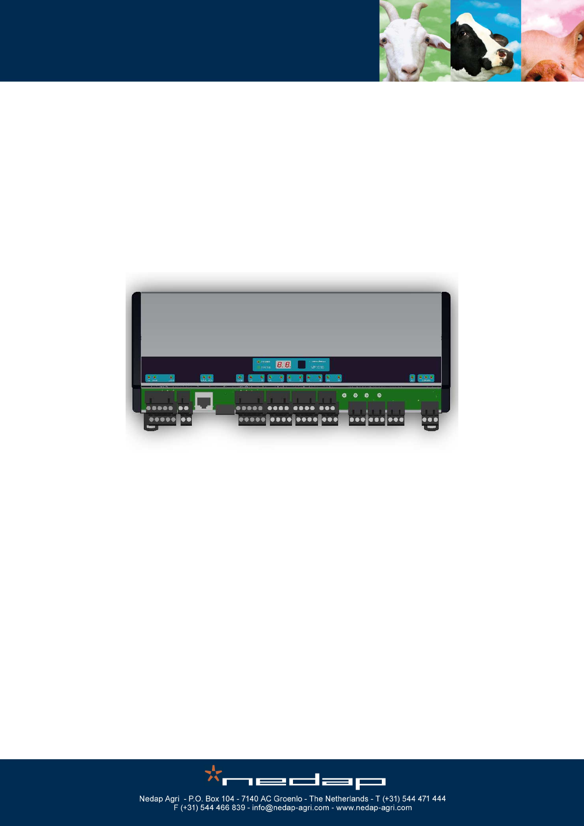
1 Introduction
The Velos VP1910 is used for identification of animals and for controlling processes. The VP1910 must
be connected to a computer (controller) and can communicate by a LAN, CAN, RS485 or VC3
protocol. The connected computer must give controlling commands to the VP1910 to operate inputs,
outputs and identification.
The VP1910 has the following main tasks:
- Identification of tags (ISO 134.2 kHz FDX/HDX)
- Controlling outputs - 5 outputs are available to activate e.g. lights, valves, relays
- Reading inputs - 5 inputs available for e.g. sensors, switches
- Digital noise filtering (European Burg Mainflingen filter)
Following antenna types can be used:
- V-sense antennas with auto tuning
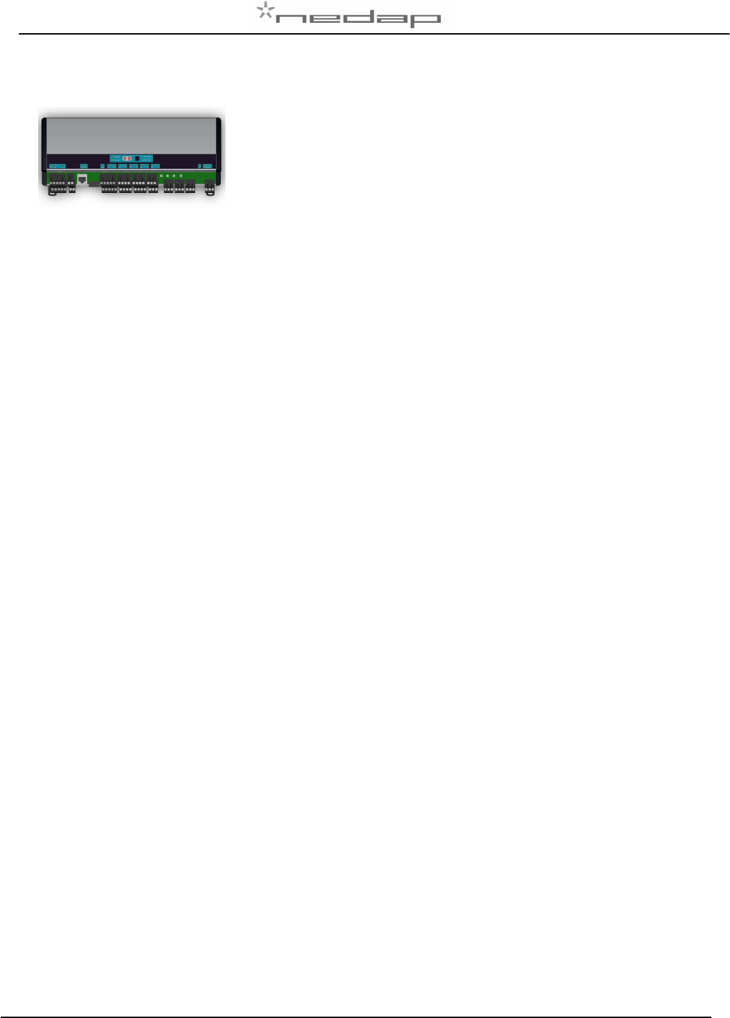
The VP1910 must be installed in a housing suitable for farm conditions, for example in a V-box.
Figure : V-box2 with a VP1910 reader
VP1910-200PM-00 ISO DSP Reader IO Manual version 1.2 / Page 2
2 Description and functioning
A VP1910 has 5 inputs used for reading e.g. sensors or switches.
There are also 5 outputs available to activate e.g. lights, valves or relays.
The VP1910 can read tags FDX/HDX 134.2 kHz.
In case installing in or near Germany there is a filter available to reduce disturbance for transmitters
near Burg and Mainflingen.
The VP1910 must be connected to a computer and can communicate by a LAN, CAN, RS485 or VC3
protocol. The connected computer must give controlling commands to the VP1910 to operate inputs,
outputs and identification.
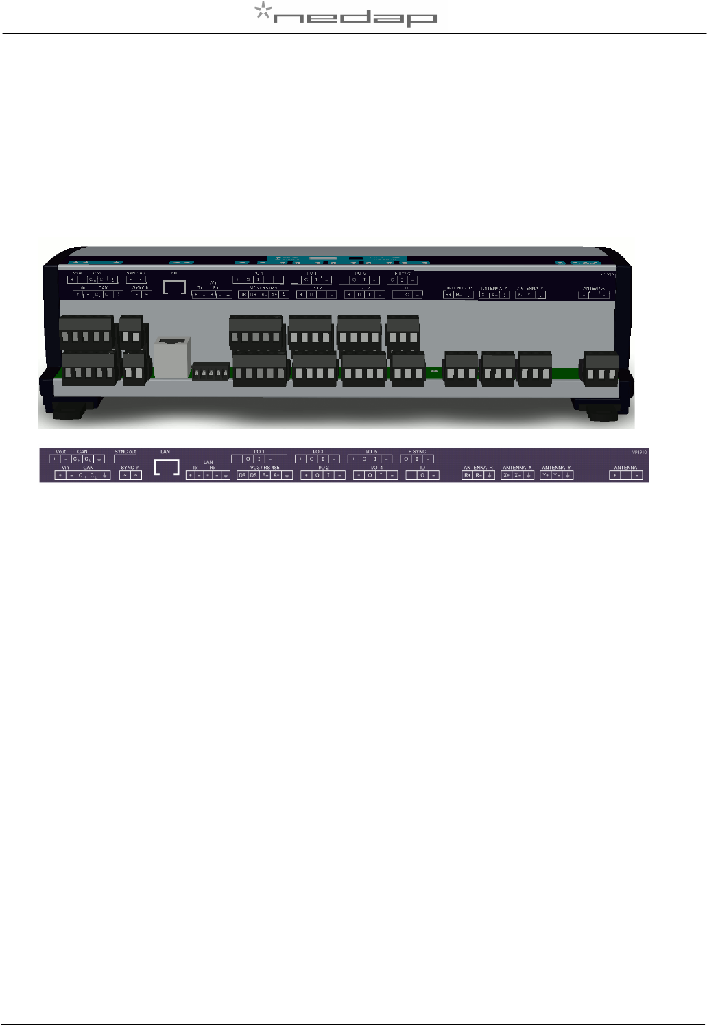
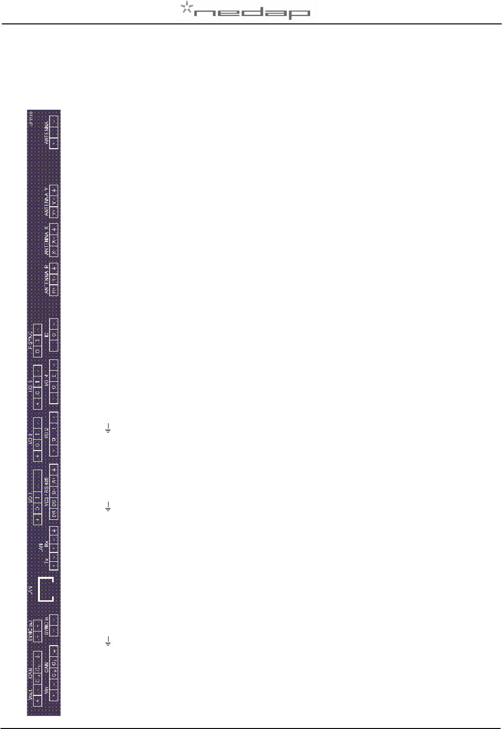
Figure : Sticker on the VP1910 with indication of the connections
Operation of the VP1910
Antenna : for reading tags, normally on
Inputs : read continuously with status change sent to the controller
Outputs : switched on or off by commands from the controller
LEDs : switched on or off by the VP1910 according to the status
Error : errors are sent to the controller
All inputs and outputs can be tested by the use of the push button and display. For operation of the
push button and display see appendix B.
3 Safety
Installation and service only by trained personnel.
Always turn off the main power when working on the electrical installation.
4 Installation
Installation consits of the following steps:
1. Mounting
2. Installation of all wiring (connections)
3. Power up
4. Set address (when more than one VP1910)
5. Check and set required settings
6. Antenna adjustment (green LED on)
7. Checking the connected equipment like lamps, sensors etc.
8. Configuration in the PC
Follow this manual to complete the steps.
4.1 Mounting
See the relevant equipment manual relating to where the VP1910 is to be installed.
VP1910-200PM-00 ISO DSP Reader IO Manual version 1.2 / Page 3
4.2 Connections
See the relevant equipment manual relating to where the VP1910 is to be installed. See also appendix
E, F and G for the different connection possibilities.
-
+
-
o
-
I
o
-
I
+
O
A-
B-
DS
DR
RX-
RX+
TX-
TX+
~
~
CL
CH
-
+
Antenna
Antenna (shield of coax)
Antenna (core of coax)
Antenna Y X Z
Not used
ID (external lamp to indicate ID)
Minus
Plus
F-sync (antenna frequency synchronisation)
Minus
In
Out
I1 – I5 (I=input)
Minus
Input contact
O1 – O5 (O=output)
plus
Output
VC3 / RS485
Ground
RS485
RS485
VC3 data send
VC3 data receive
LAN
Ground
Receive
Receive
Transmit
Transmit
Sync in/out (ISO sync)
Antenna synchronisation (twisted pair)
Antenna synchronisation (twisted pair)
Velos CAN
Ground
CAN high (wire is twisted pair with CL)
CAN low (wire is twisted pair with CH)
V in / V out
Minus
Input voltage 24 VDC

VP1910-200PM-00 ISO DSP Reader IO Manual version 1.2 / Page 4
5 Adjustments
Before starting with adjustments first install all components and wiring. Follow the sequence as
indicated in this chapter.
5.1 Check after power up
Check if the VP1910 has power after power up.
For more details about the LED indicators see Appendix D.
If LED’s are green, continue with address settings
5.2 Communication
Check if the VP1910 has communication leds switched on.
5.3 Address
Each VP1910 requires a unique address on the communication bus. Use the display and push button
to set the address. How to use the display and push button is shown in appendix B. See appendix C
for the complete overview of the display menu.
The display will indicate the actual address at startup (01 for a new unit). If an address is accepted by
the communication bus the display goes blank. If there is no communication with the controller also the
address is shown. If the address is not accepted, the display will show the address.
How to change an address (for example set address to 12)
1. Short press on the button. Ad will appear.
2. Now hold the button till the display starts blinking. dA will appear.
3. Short press on the button. SA will appear.
4. Now hold the button until the display starts blinking. 0- will appear.
5. Short press on the button. The 0- is now changed into 1-.
6. Hold the button until the display starts blinking. 10 will appear.
7. Short press on the button. The 10 is now changed into 11.
8. Short press on the button again. The 11 is now changed into 12.
9. Hold now the button until the display starts blinking. The 12 is now stored in the memory.
10. There will now be 12 blinking on the display now. If the address is accepted by the process
unit the display goes blank.
How to check the address
1. Short press the button. Ad will appear.
2. Now hold the button until the display starts blinking. dA will appear.
3. Hold the button again until the display starts blinking. The actual address will be shown.
4. Leave the menu by pressing the button until the display goes blank.
If the display does not go blank (address remains on the display), the address in not accepted.
When the address setting is ok continue with the antenna adjustment.

VP1910-200PM-00 ISO DSP Reader IO Manual version 1.2 / Page 5
5.4 Antenna tuning
After the first time power up the antenna tuning must be checked. Check the TUNING LED, green is
OK and means the antenna is correctly tuned.
Green on Antenna tuning ok
Red blinking Antenna resistance too high, in case of EWA readjust.
Red on Antenna out of range
Red on Antenna out of range
Red blinking No antenna connected or low antenna signal
All off Antenna switch off by the software
See also the manual of the antenna being used for information about tuning
Two parrallel auto tune antenna's
In situations where two auto tune antenna's are installed in parrallel of each other, the minimal
distance must be at least 200cm measured from center to center.
Before powering up the readers, the antenna's must be locked and both ISO and FSYNC cabels must
be installed. Both antenna's must have the same polarity (faces in the same direction).
1. After power up and a few seconds, one or more tuning leds will toggle.
2. Unlock the first antenna's for 10 seconds and lock again.
3. Wait for 5 seconds and unlock the second antenna for 10 seconds and lock again.
4. Wait for 10 to 60 seconds to get both readers in the mode where the center green leds are
continuously on.
5. If the center green leds are not continuously on after 60 seconds, restart with step 2.
6. Verify the valid power level on both readers, and adjust if neccesary. The displayed level is the
current level and is subject to rounding errors and the measured antenna impedance. If the displayed
value is outside 10% tolerance, the level must be adjusted.
7. Unlock the first antenna for 5 seconds and lock again.
8. Unlock second antenna for 5 seconds and lock again.
9. Power off both readers.
10. Power on both readers and verify after a few seconds that both readers has their center tuning led
continuously on and that the power levels are within 10% tolerance of the programmed level.
VP1910-200PM-00 ISO DSP Reader IO Manual version 1.2 / Page 6
5.5 Antenna power
The antenna power default is set to 25% (max 99) and can be set higher for more antenna power.
Lowering the antenna power will reduce the reading distance of the antenna. See table below for
maximum power level.
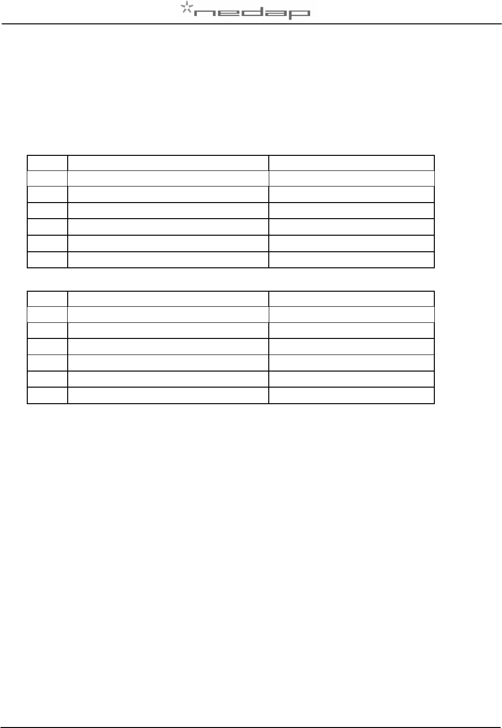
Max antenna power USA and Canada
Antenna Model Power setting of the VP1910 (%)
1 VP6150 60
2 VP6151 66
3 EWA Walk Through Loop antenna 37
4 VP6154 Walk Through Loop antenna 26
5 EWA Walk Over Loop antenna 55
6 VP6154 Walk Over Loop antenna 39
Max antenna power Europe
Antenna Model Power setting of the VP1910 (%)
1 VP6150 99
2 VP6151 99
3 EWA Walk Through Loop antenna 89
4 VP6154 Walk Through Loop antenna 63
5 EWA Walk Over Loop antenna 99
6 VP6154 Walk Over Loop antenna 93
Check the antenna power
level
The antenna power level is shown on the display in the service menu at HF option AP (Adjust Power)
1. Select menu option AP (Adjust Power) on the display by using the push button
2. Push the button until the display starts to blink, a value will appear on the display
3. The value on the display is the actual power setting. 99 is the default factory setting.
4. To leave the menu without modifying the settings press the button until the display goes blank
(press about 4 seconds)
Modify the antenna power level
1. Select the actual antenna power on the display (see above antenna power check)
2. Short press on the button and the first digit of the value will change
3. Continue to press until the desired value, then hold the button until blinking
4. The second digit can be changed in the same way
5. When the desired value is on the display, press until the display blinks
6. The next menu item AS is now indicated.
7. To leave the service menu and return to normal operation, press the button until the display
goes blank (press about 4 seconds)
5.6 Software setup
The software in the connected controller determines how the inputs and outputs on the VP1910 are
controlled. See manual with the relevant settings to configure the software for this VP1910.
When the software setup is done the VP1910 is ready for use.

VP1910-200PM-00 ISO DSP Reader IO Manual version 1.2 / Page 7
6 Advanced
Tests and adjustments described in this chapter are not used for a standard startup and configuration
of the VP1910.
6.1 Testing inputs and outputs
There are two types of output tests. An output test to switch the output on and off. There is also
available an input test for checking connected equipment like switches and sensors.
Use the display and push button for testing, see appendix B how to use it.
Output test
Use the test L1, L2, .. L6 to test the connected equipment e.g. lights, valves or relays. This test will
switch on the selected output. The test is stopped by a short press on the button.
Example of a light test (connected to output 6)
1. Short press on the button until “It” appears.
2. Now hold the button until the display starts blinking. “dE” will appear.
3. Short press on the button until “L6” appears.
4. Now hold the button until the display starts blinking. Output 6 will be switched on. To switch off,
a short press on the button.
Input test
Use the test i1, i2, .. i5 to test the connected equipment e.g. switches and sensors. This test will read
the selected input. The results are indicated with a “0” or “1”. Open or closed depends on the settings
from the behavior component. The test is stopped by a short press on the button.
Example of a switch test (connected to output 5)
1. Short press on the button until “It” appears.
2. Now hold the button till the display starts blinking. “dE” will appear.
3. Short press on the button until “i5” appears.
4. Now hold the button until the display starts blinking. Input 5 will be read.
5. Activate the switch on and off. If ok, the display value will show zero and one
6.2 Advanced antenna adjustment
Antenna squelch
Antenna squelch is a possibility to set a threshold for the ID level of a tag. It means the antenna power
is still the same, but the software will not transfer weak received tag numbers.
The antenna squelch default is set to minimum (-0). This means no threshold. Maximum is -9.
There is squelch setting for FDX and HDX.
Check the antenna squelch level
The antenna squelch level is shown on the display in the service menu at HF, option AS (Adjust
Squelch)
1. Select menu option AS (Adjust Squelch) on the display by using the push button
2. Select menu option AF (FDX) or AH (HDX) on the display by using the push button
3. Push the button until the display starts to blink, a value will appear on the display
4. The value on the display is the actual setting. -0 is the default factory setting.
5. To leave the menu without modifying the settings press the button until the display goes blank
(press about 4 seconds)
Modify the antenna squelch level
1. Select the actual antenna squelch level on the display (see above squelch level check)
2. Short press on the button and the value will change
3. Continue to press until the desired value, then hold the button until blinking
4. The next menu item “df” is now indicated.
5. Hold a tag in the antenna and determine the maximum reading distance

VP1910-200PM-00 ISO DSP Reader IO Manual version 1.2 / Page 8
6. If reading distance is ok leave the menu. If not ok try another level.
7. To leave the service menu and return to normal operation, press the button until the display
goes blank (press about 4 seconds)

VP1910-200PM-00 ISO DSP Reader IO Manual version 1.2 / Page 9
Antenna tuning with option “AA”
With HF menu option “Adjust Antenna (AA)”, it is possible to see the antenna tuning on the display.
The display value is an indication and shows minimal value when tuned ok.
Return iden
ti
ficatio
n settings to factory defaults
There is an option available called “dF” to set the antenna settings back to factory settings.
How set back to factory defaults
1. Select the option “dF” on the display.
2. Press button until blinking. “OF” will appear now.
3. Short press on the button, “On” will appear. Press until blinking. The defaults are now restored.
“OF will now be on the display.
4. To leave the service menu and return to normal operation, press the button until the display
goes blank (press about 4 seconds)
6.3 Identification test options
Identification test
with option “id”
When a tag is in the antenna field, the green LED used for ID will be on. There is also a test in the
internal test menu called “id”. This test will also show the green LED on but also shows the last two
digits of the tag number on the display.
Signal
level indication
option “SF” and “SH
”
There is a test available to give an indication about the signal received on the reader of the VP1910.
This test is separated in a FDX (SF) and HDX (SH) noise indication test. This test is mainly used for
HDX because at HDX there is a greater risk of external influence on the antenna field.
How to use the signal level test
1. Select option “SH” on the display and press the button until the display starts to blink. A value
will appear on the display.
2. Now move a HDX tag slowly into the antenna field. The display value will normally increase
when getting closer to the antenna. If there is negligible or little increase in display value this is
an indication something external is causing noise.
The possible cause of noise can be frequency controlled electric motors or a transmitter operating on
or close to 134.2 kHz

VP1910-200PM-00 ISO DSP Reader IO Manual version 1.2 / Page 10
7 Trouble shooting
Errors / malfunctioning is indicated by the indicator LED’s or the display.
Error by indicator LED
Indicator LED’s are normally green or switched off. A red or orange indicator LED means normally
there is something not ok. See Appendix D for the explanation of the different colors.
E
rrors indicated at
m
enu option “dE”
In menu option “dE” it is possible to see actual error codes. When entering the display menu option
“dE” the errors code will be shown and the error will be cleared. If the error is not cleared it means
there is still an error. There can be more than one error. Further errors are displayed one after another
with a short delay between each code.
“dE” code on the display Description
- - No errors
Identification performance and disturb
ance
Identification performance can be reduced by disturbance caused by variable-frequency drives used
for ventilation, milk pumps, vacuum pumps, etc. Also ballasts used for fluorescent tube lighting may
interfere. If there is interference one can locate the source by switching off all the equipment on a farm
and then switch them on again one by one. Most of the time when a variable-frequency drive is
causing a problem it is due to bad installation or without the mandatory main filters.
8 Maintenance, cleaning and disposal
Maintenance
No regular maintenance required.
Software update
A VP1910 is equipped with software to activate inputs and outputs, display / push button and a motor
safeguard. This software is called firmware. During manufacturing the firmware is programmed and
ready for use. In case of an update it is possible to download new firmware thru the CAN-bus. In the
Velos system the web browser interface of the VPU (VP8001) is used to handle this. For more details
about downloading new firmware see also the manual of the VPU (VP8001).
Cleaning
A VP1910 must be installed in a suitable housing (V-box) so cleaning of the VP1910 is not required.
Disposal
Discard according to the regulations prevailing at the time of disposal

VP1910-200PM-00 ISO DSP Reader IO Manual version 1.2 / Page 11
Appendix A: Specifications
Specifications VP
1910
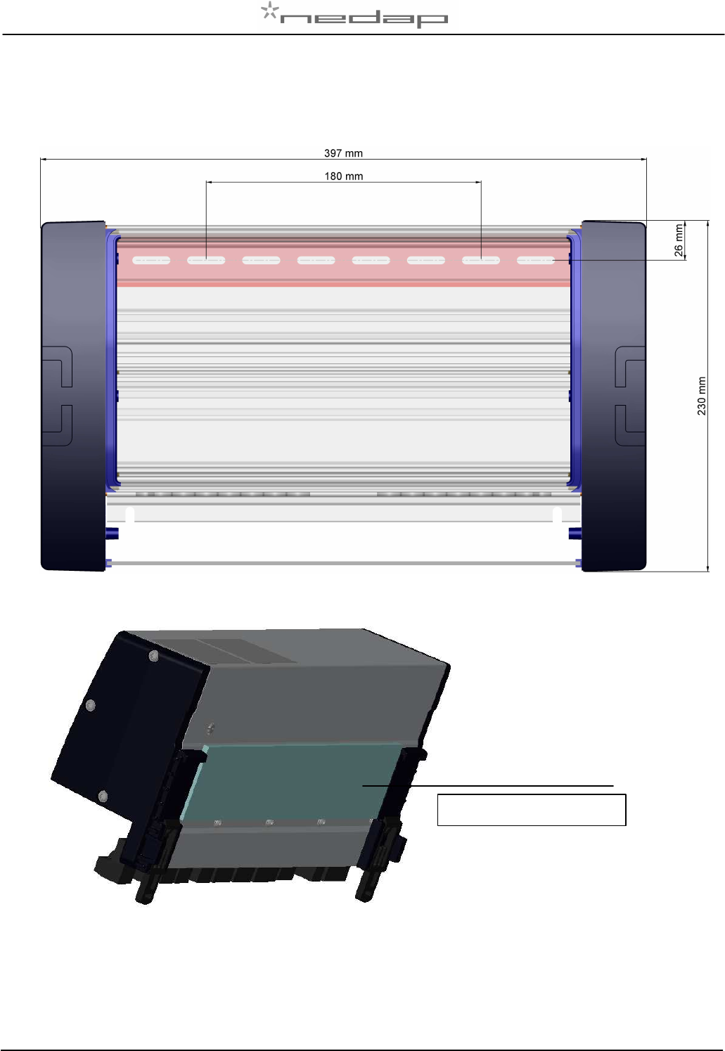
Dimensions 290 x 128 x 70 mm LxWxH (excluding mounting rail) Weight: ± 1200 gr
Power Input voltage 25 VDC, +20% -20%
Power consumption minimum 7 Watt / maximum 35 Watt
Protected against reverse connection power supply
Communication Ethernet, CAN, RS485 and VC3 (slave)
Software Downloadable thru network CAN and Ethernet
Inputs Reading inputs digital.
Suitable for NPN sensors en switches to ground.
Outputs Max. 0.4 Amp per output short-circuiting en terminal protected.
Total output current limited to 3A.
Antennas Antennas with autotune, check antenna manual
Detection distance Varies per antenna
Synchronisation Synchronization according to ISO 11785
Environment Temperature: Operating: -10 – 50 °C, St orage: -25 – 70 °C
Relative humidity: 10 – 93% non condensing
IP class IP 30. When installed in V-box IP 65 (cover and cables installed correctly!)
Cable specifications
Power
CAN-bus Min. 1.5 mm
2
Min. 0.34 mm2 twisted pair shielded
Antenna Coax RG58. Max. length depending on antenna type.
Outputs CE approved at cable length < 3m
Inputs CE approved at cable length < 3m
Frequency Sync Coax RG 58 < 3m
ISO Synchronisation Twisted pair min. 0.34mm
2
shielded Total max. 500m
Always use a NEDAP power supply
The Nedap guarantee-regulations are only valid when is installed as indicated in this manual.
Install data cables at a safe distance from (high) powered cables
More information
For more detailed information contact your local Nedap supplier or check the internet site.
VP1910-200PM-00 ISO DSP Reader IO Manual version 1.2 / Page 12
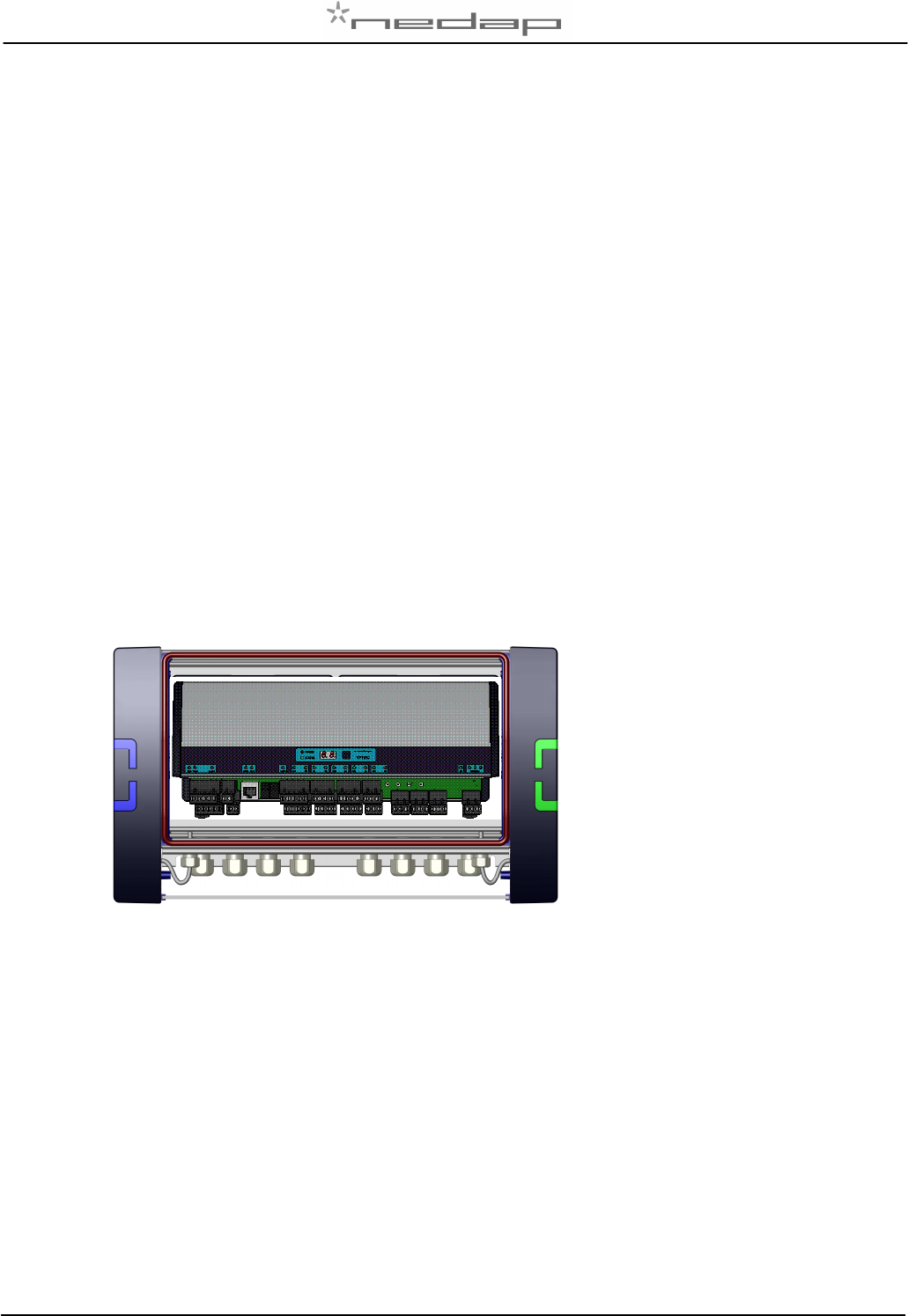
Appendix B: Installation in V-box
remove protective film
VP1910-200PM-00 ISO DSP Reader IO Manual version 1.2 / Page 13
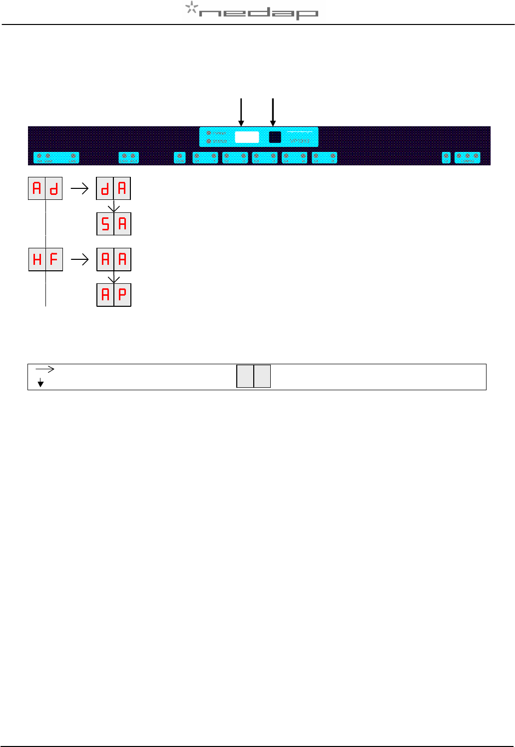
Appendix C: Display and push button
DISPLAY ADDRESS
Shows the actual address
SET ADDRESS
Change the address
ADJUST ANTENNA
ANTENNA POWER
Figure: a section of a display menu
Press button until blinking
Short press on button
To leave menu:
Press button until display goes blank
How to use the display and push button
Normally the display is off. If there is no connection to the VPU the address is shown. It is also possible
some program states of a behavior component are shown during operation.
Activate the menu short press on the button, the display menu is shown
Scroll down short press on the button
Select press button until blinking
Change and store select item to change, open item by pressing button until blinking, change by
short press on button, store by pressing button until blinking
Check a setting select the item to check, press button until blinking, first value shown is actual
setting
The display is normally automatically switched off after 30 minutes.
Display Push button
VP1910-200PM-00 ISO DSP Reader IO Manual version 1.2 / Page 14
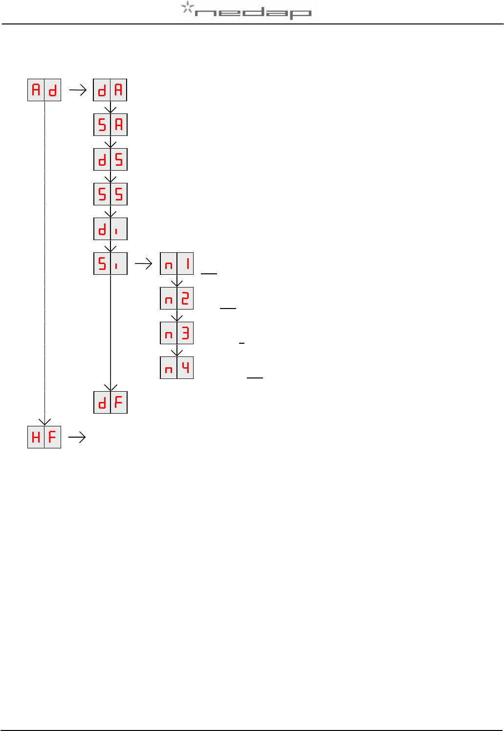
Appendix D: Overview display menu
DISPLAY ADDRESS
Shows the actual address
SET ADDRESS *
Change the address
DISPLAY SECTION
Show section (Default 1)
SET SECTION
Change section
DISPLAY IP ADDRESS
Shows actual IP address (one by one)
SET IP ADDRESS
192.168.1.101
SET IP ADDRESS
192.168.1.101
SET IP ADDRESS
192.168.1.101
SET IP ADDRESS
192.168.1.101 (n=no change, y=yes for saving new IP)
SETTI
NGS TO DEFAULT
All address settings back to factory settings
Next
page
*Link between Address en IP-Address
There is a connection between address and the IP-address. The last two digits of the IP-address is
linked to the address. Changing the address will also change the last to digits of the IP-address.
Example : Address 04 = IP-address 192.168.1.104
VP1910-200PM-00 ISO DSP Reader IO Manual version 1.2 / Page 15
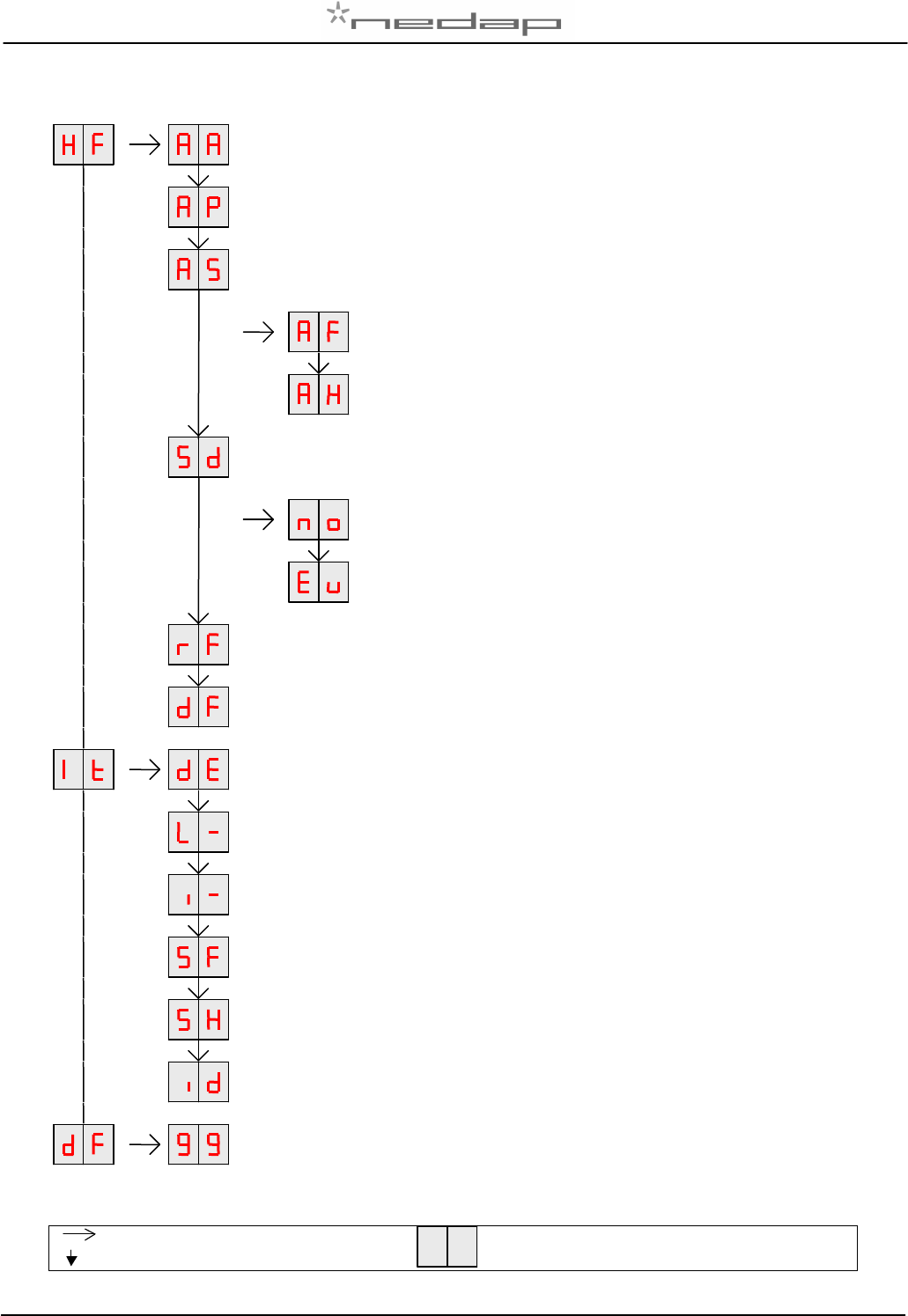
ADJUST
A
NTENNA
Antenna tuning level will be shown
ANTENNA
POWER
Min/max 10 / 99. Normally set to 25 (=25% of maximum power).
ANTENNA
SENSITIVITY SQUELCH
Min/max 9 / 0. Normally set to 0. Possible to set a lower value.
SQUELCH
LEVEL
FDX
Normally set to 0
SQUELCH LEVEL H
DX
Normally set to 0
SET DSP FILTER
No = no DSP filter
European Mainflingen filter
RF FILTER
OF=no filter on tag numbers. ON=management tag only (>900000000000000)
SETTINGS TO DEFAULT
All HF settings back to factory settings
DISPLAY ERROR
–
CLEAR ERROR
Shows error code and error clearing after showing.
TEST OUTPUT 1
-
5
L1 … L5 (L6 = external lamp ID)
TEST INPUT 1
-
5
I1 … I5
SIGNAL LEVEL FDX
Shows signal level measured by the FDX receiver
SIGNAL LEVEL HDX
Shows signal level measured by the HDX receiver
TEST IDENTIFICATION
Shows last 2 digits of a tag number
DEFAULT
Enter value 99 to return to factory defaults
(IP address 192.168.1.101)
Press button until blinking
Short press on button
To leave menu:
Press button until display goes blank
VP1910-200PM-00 ISO DSP Reader IO Manual version 1.2 / Page 16
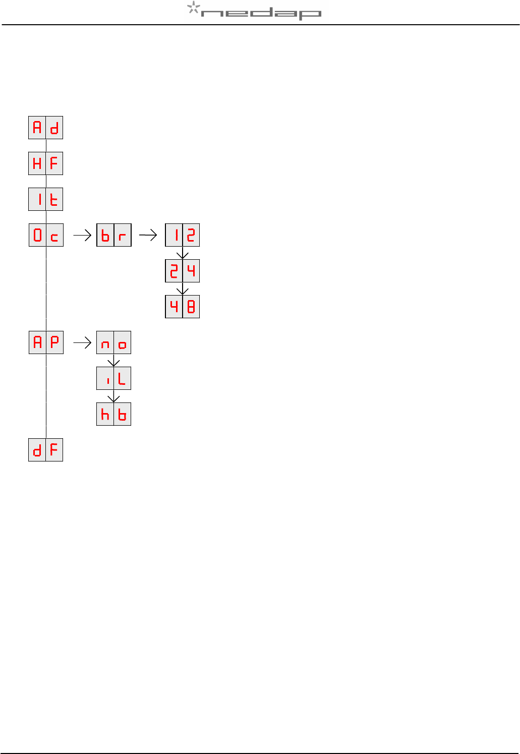
Appendix E: Overview display menu, VC3 options
Extra available options compared to standard (Appendix C)
Address, see appendix C
Antenna, see appendix C
Internal test, see appendix C
BAUDRATE
1200 baud
2400 baud
4800 baud
APLICATION
No application
ILS application
WHS application
Default, see appendix C
VP1910-200PM-00 ISO DSP Reader IO Manual version 1.2 / Page 17
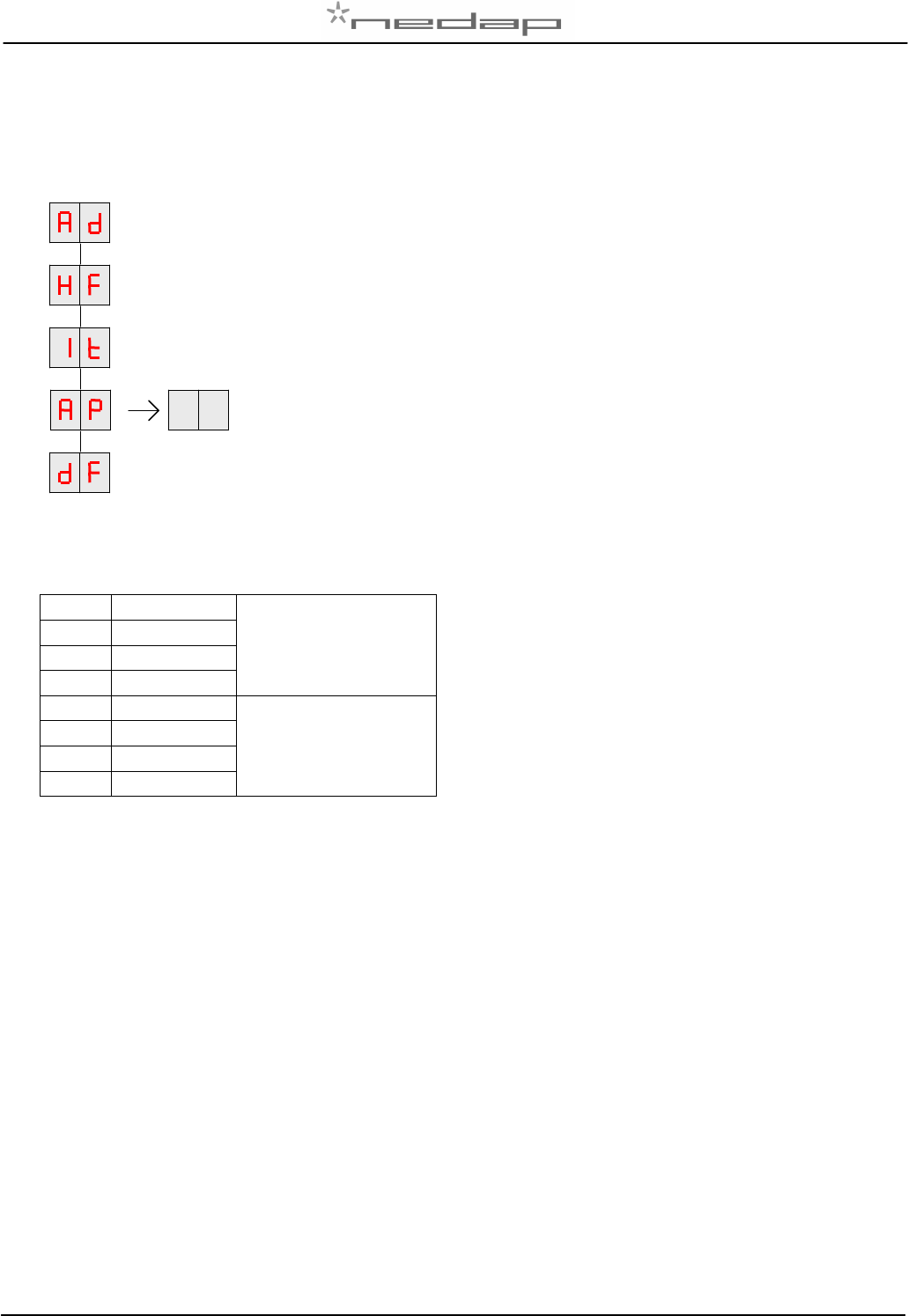
Appendix F: Overview display menu, RS485 options
Extra available options compared to standard (Appendix C)
Address, see appendix C
Antenna, see appendix C
Internal test, see appendix C
COMMUNICATION PROTOCOL
Enter a value from table below
Default, see appendix C
COMMUNICATION PROTOCOL combinations
00
2400 bps No end terminal
01
9600 bps
02
19200 bps
03
38400 bps
16
2400 bps End terminal
17
9600 bps
18
19200 bps
19
38400 bps
VP1910-200PM-00 ISO DSP Reader IO Manual version 1.2 / Page 18
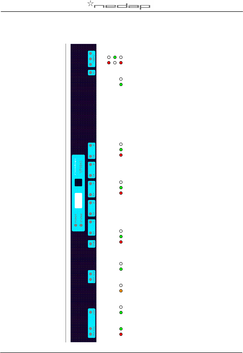
Appendix G: LED indicator overview
Tuning
Antenna tuning OK
No antenne connected of out of range
ID
No tag identified
Tag identified
I1 – I5 (I=input)
Input contact open
Input contact closed
Error
O1 – O5 (O=output)
Output not active
Output switched on
Error
COM (RS485 – VC3)
No communication
Communication
Error
ACT (LAN)
No communication
Communication
LAN
No communication
Communication 100mps
LAST (can bus)
Not last on CAN bus
Last on CAN bus
Vin - Vout (Power IN - OUT)
Power on
Error
VP1910-200PM-00 ISO DSP Reader IO Manual version 1.2 / Page 19
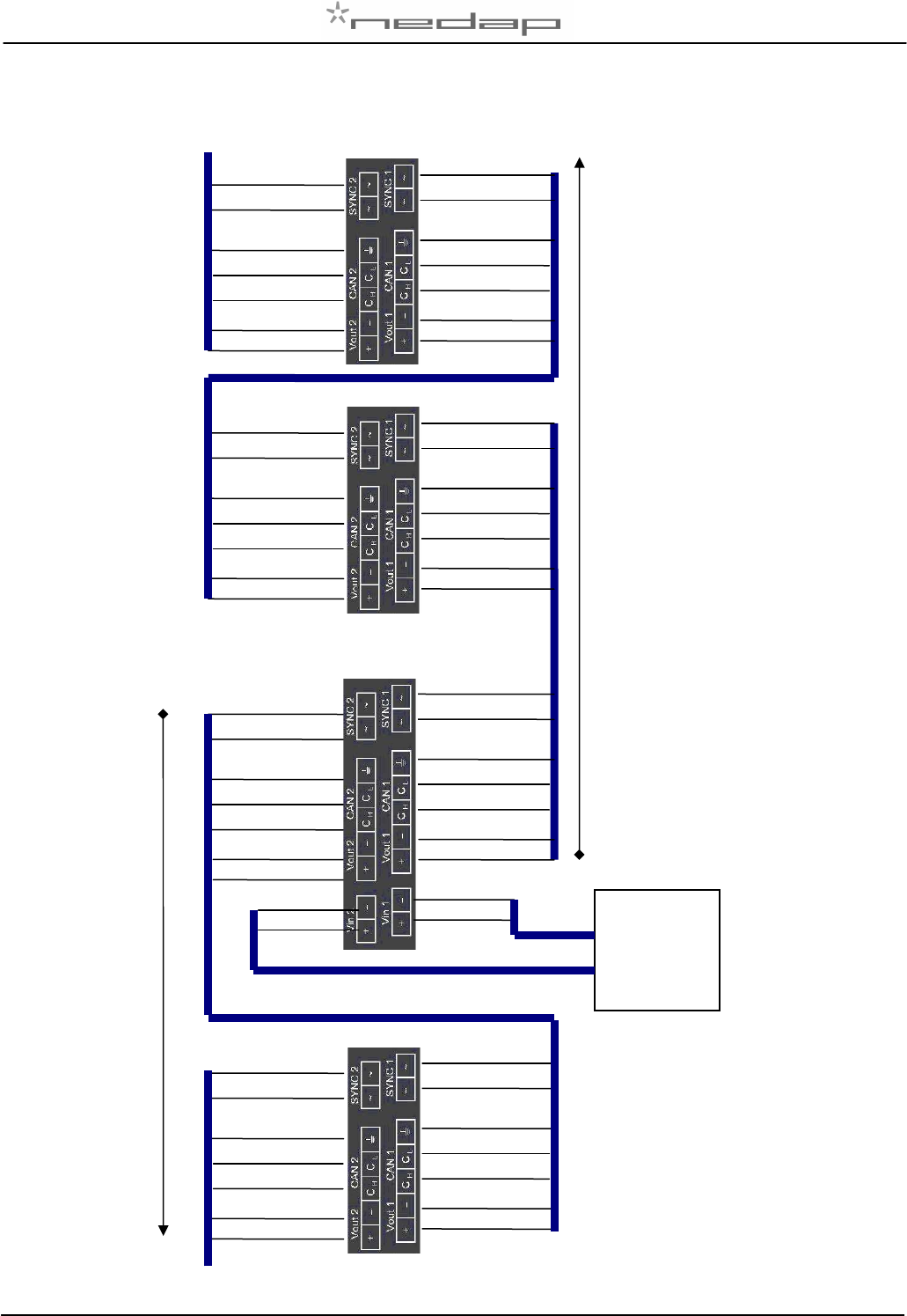
Appendix H: VP1910 connected to a Velos VP8001 (VPU)
VP8001
(V-pu) VP1910
VP1910
VP1910
next
next
red
black
orange
orange/white
blue
blue/white
red
black
orange
orange/white
blue
blue/white
shield
shield
red
black
orange
orange/white
blue
blue/white
shield
red
black
orange
orange/white
blue
blue/white
shield
red
black
orange
orange/white
blue
blue/white
red
black
orange
orange/white
blue
blue/white
shield
shield
CAN channel 2
CAN channel 1
red
black
orange
orange/white
blue
blue/white
red
black
orange
orange/white
blue
blue/white
shield
shield
red
black
Power
supply
(VP2001)
red
black
VP1910-200PM-00 ISO DSP Reader IO Manual version 1.2 / Page 20
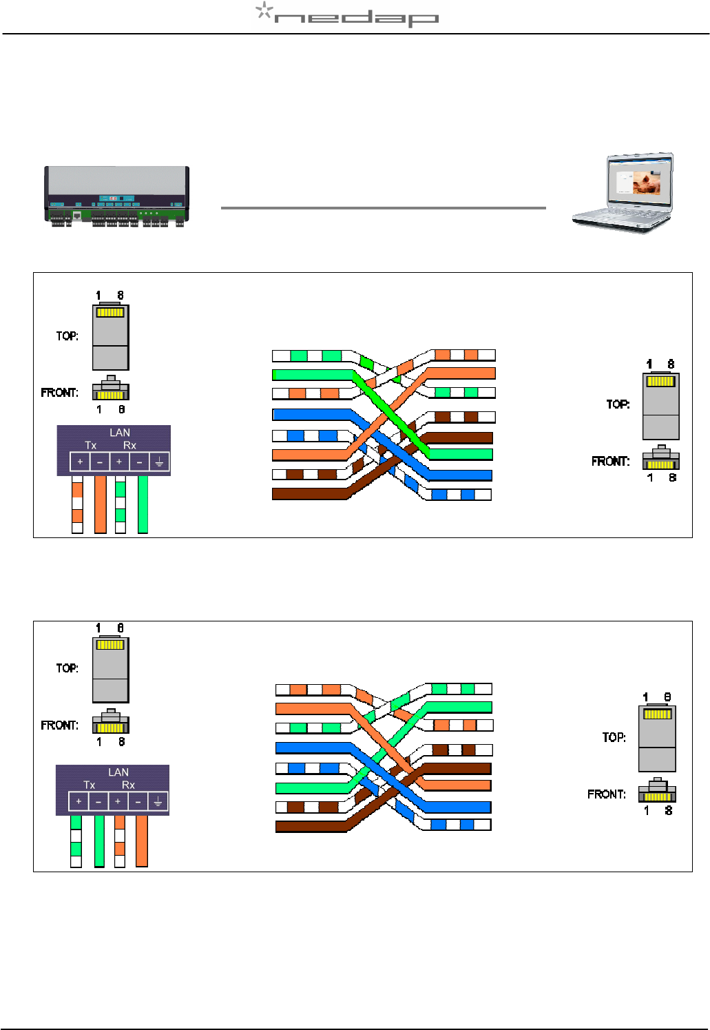
Appendix I: LAN Ethernet crossover cable
LAN Ethernet crossover cable (TIA/EIA 568A)
LAN Ethernet crossover cable (TIA/EIA 568 B)
White - Green
White - Blue
White - Orange
White - Green
Brown
1
2
3
2
4
5
6
7
8
6
Blue
Orange
White
-
Brown
Green
1
2
3
4
5
7
8
Blue
-
White
White
-
Brown
White - Orange
Green
Blue
Orange
Brown
1
2
3
4
5
6
7
8
6
Blue
White - Green
White - Orange
Brown
Green
White - Brown
Orange
1
2
3
4
5
7
8
Blue
-
White
White
-
Brown
White - Orange
White - Green
White - Blue
Orange
Blue
Green
Brown
Cross cable (max 100m)
VP1910-200PM-00 ISO DSP Reader IO Manual version 1.2 / Page 21
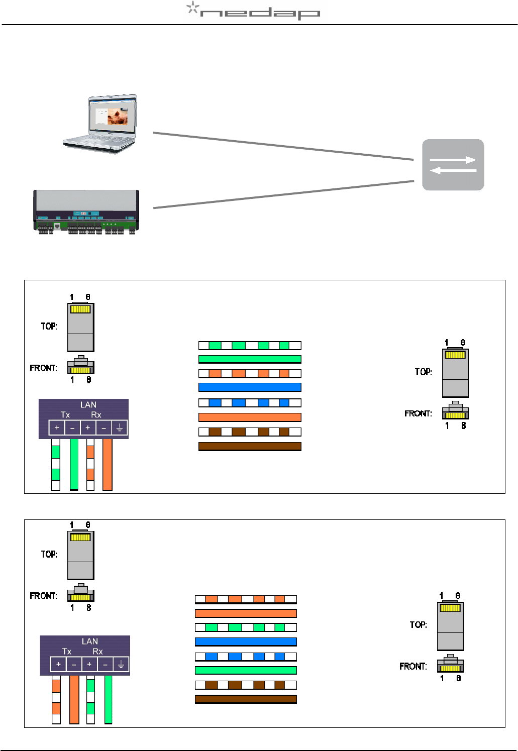
Appendix J: LAN Ethernet straight cable
LAN Ethernet straight cable (TIA/EIA 568A)
LAN Ethernet straight cable (TIA/EIA 568 B)
1
2
3
2
4
5
6
7
8
6
White
-
Brown
White - Green
White - Orange
White - Blue
Green
Blue
Orange
1
2
3
2
4
5
7
Brown
1
2
3
2
4
3
5
6
8
Orange
Blue
Green
White
-
Brown
1
2
3
2
4
3
5
6
7
8 Brouwn
White - Orange
White - Green
White - Blue
7
Straight cable (max 100m)
Straight cable (max 100m)
Switch
VP1910-200PM-00 ISO DSP Reader IO Manual version 1.2 / Page 22
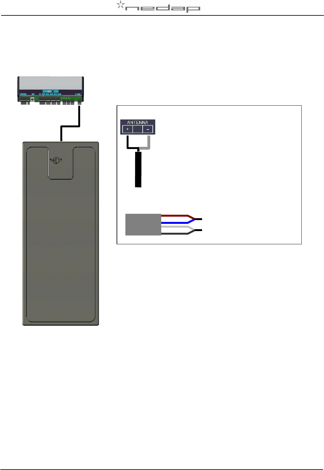
Appendix K: Antenna connection
VP6150 antenna connection
Antenna HF+
(Brown / Blue)
Antenna HF- (Black / White)
VP1910-200PM-00 ISO DSP Reader IO Manual version 1.2 / Page 23
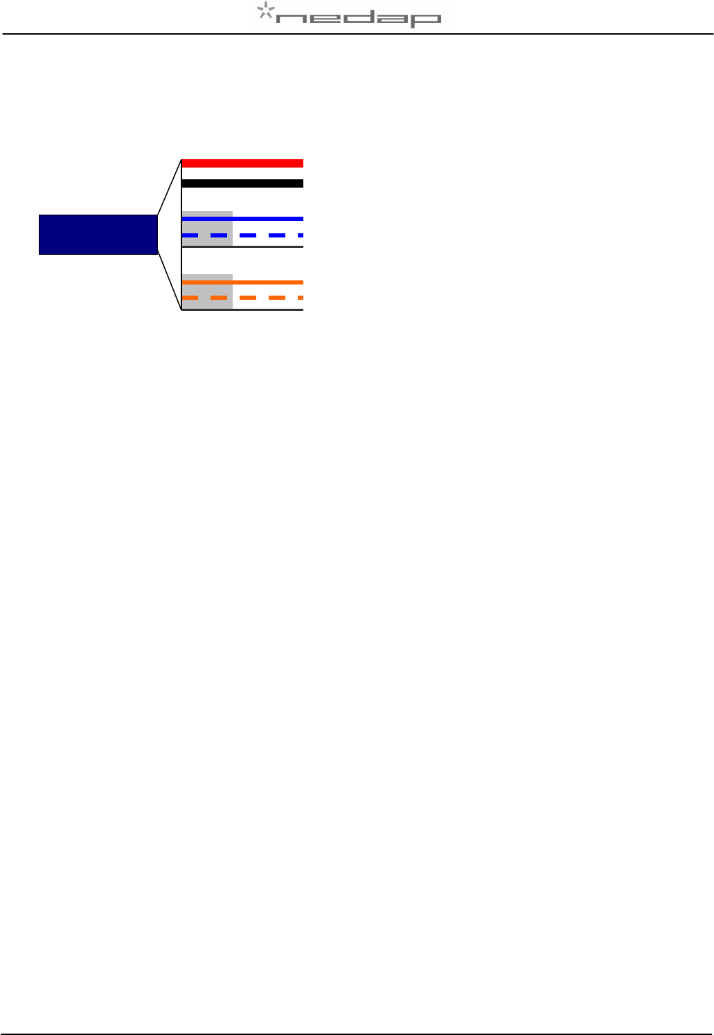
Appendix L: Velos cable
Details Velos cable
Red (+)
Black (-)
Blue (Ch)
Blue/white (Cl)
Shield
Orange (Sync)
Orange/white (Sync)
Shield
Power
1,5 mm2
Communication
0,34 mm2
Twisted pair shielded
HF Synchronisation
0,34 mm2
Twisted pair shielded
Part No. 7705310
VP1910-200PM-00 ISO DSP Reader IO Manual version 1.2 / Page 24
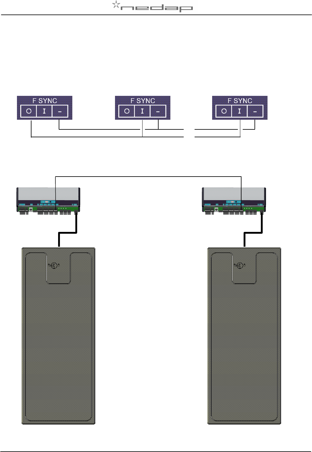
Appendix M: Two antennas < 3m distance
Use a F-sync cable to sync both readers.
master
Coax RG58
F
-
sync kabel