Nedap N V XQMK2 Anti-Pilferage Device User Manual 14 Users Manual CGDXQMK2
N. V. Nederlandsche Apparatenfabriek NEDAP Anti-Pilferage Device 14 Users Manual CGDXQMK2
UserManual.wiki
>
Nedap N V
>
XQMK2 User Manual
>
User manual
Contents
1.
Advertising literature
2.
User manual
3.
Installation manual
4.
Product literature
User manual
Navigation menu
Upload a User Manual
Namespaces
Wiki Guide
HTML
PDF
Info
Views
User Manual
Discussion / Help
Navigation
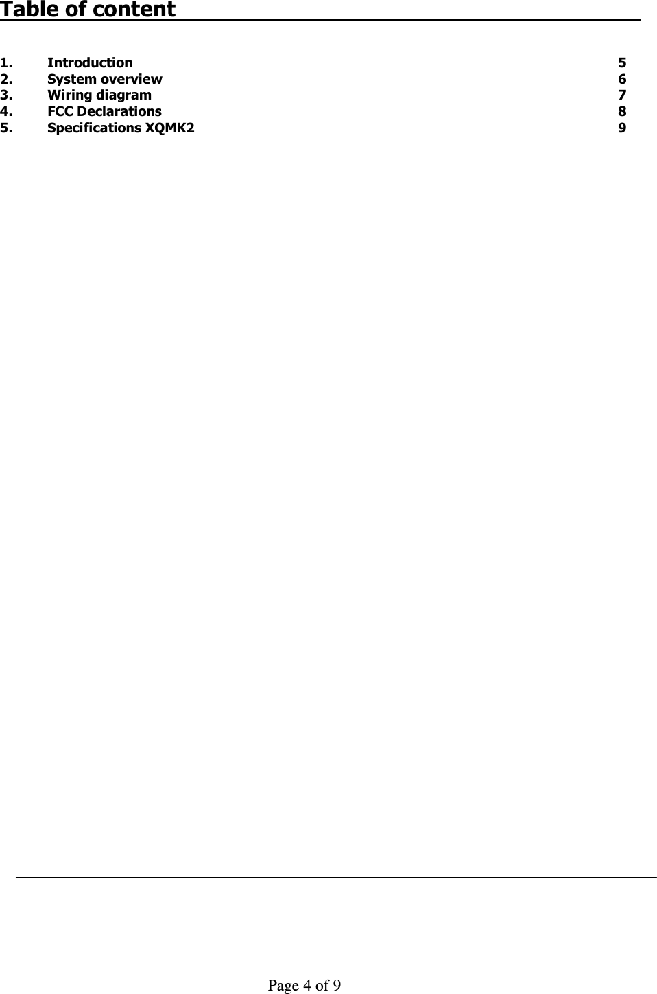
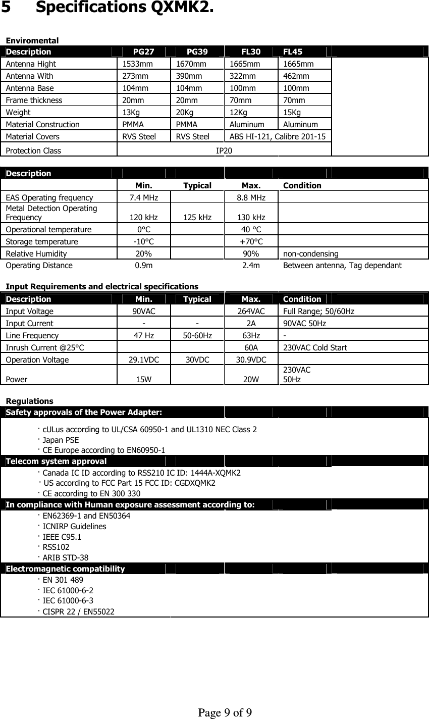
![Page 6 of 9 2 System overview Figure 1 Functional system overview The XQMK2 system consists of the following components: 1. XQMK2 Tx Unit 2. XQMK2 Rx Unit 3. NCC unit for communication 4. Power inserter 5. Antenna frame 27 cm Model: PG27 6. Antenna frame 39 cm Model: PG39 7. Antenna frame 30 cm Model: FL30 8. Antenna frame 45 cm Model: FL45 9. Customer Counting unit including Lighting 10. Customer counting unit Rx 11. Customer counting unit RxTx 12. Customer counting unit Tx 13. Optional communication units: a. PSTN: MT5600SMI-92 by Multitech CE approved, Canada IC: 125 11142A and USA FCC complies with 47 CFR Part 68: AU7USA-46014-MD-E or any other CE, FCC and IC approved PSTN. b. GSM/GPRS: MTSMC–G-F4 by Multitech CE approved, Canada IC: 125A-0027 and USA FCC ID: AU79U07A31817 or any other approved FCC or IC approved GSM c. LAN: XPORT by Lantronix d. WiFi: IEEE 802.11b WiPort 485 by Lantronix FCC ID: R68WIPORTG IC-ID:3867A-WIPORTG The XQMK2 system is complete wired up and ready for use. You only have to follow up the next steps. o Install the XQMK2 system according the: XQMK2 installation guide lines; o Power up the XQMK2 system; o Check the functionality; o Call Nedap Customer Support for quick hands-on problem solution in case of unforeseen problems [see Technical Support]; o Distance between two antennas when using hard tags Ø50 mm and FL30 antennas is: 2.2 m; o Distance between two antennas when using paper tags 4x4 and FL30 antennas is: 1.7 m; o Distance between two antennas when using hard tags Ø50 mm and FL45 antennas is: 2.45 m; o Distance between two antennas when using paper tags 4x4 and FL45 antennas is: 2.0 m; o Distance between two antennas when using hard tags Ø50 mm and PG27 antennas is: 2.30m; o Distance between two antennas when using paper tags 4x4 and PG27 antennas is: 1.80 m;](https://usermanual.wiki/Nedap-N-V/XQMK2.User-manual/User-Guide-1526096-Page-6.png)
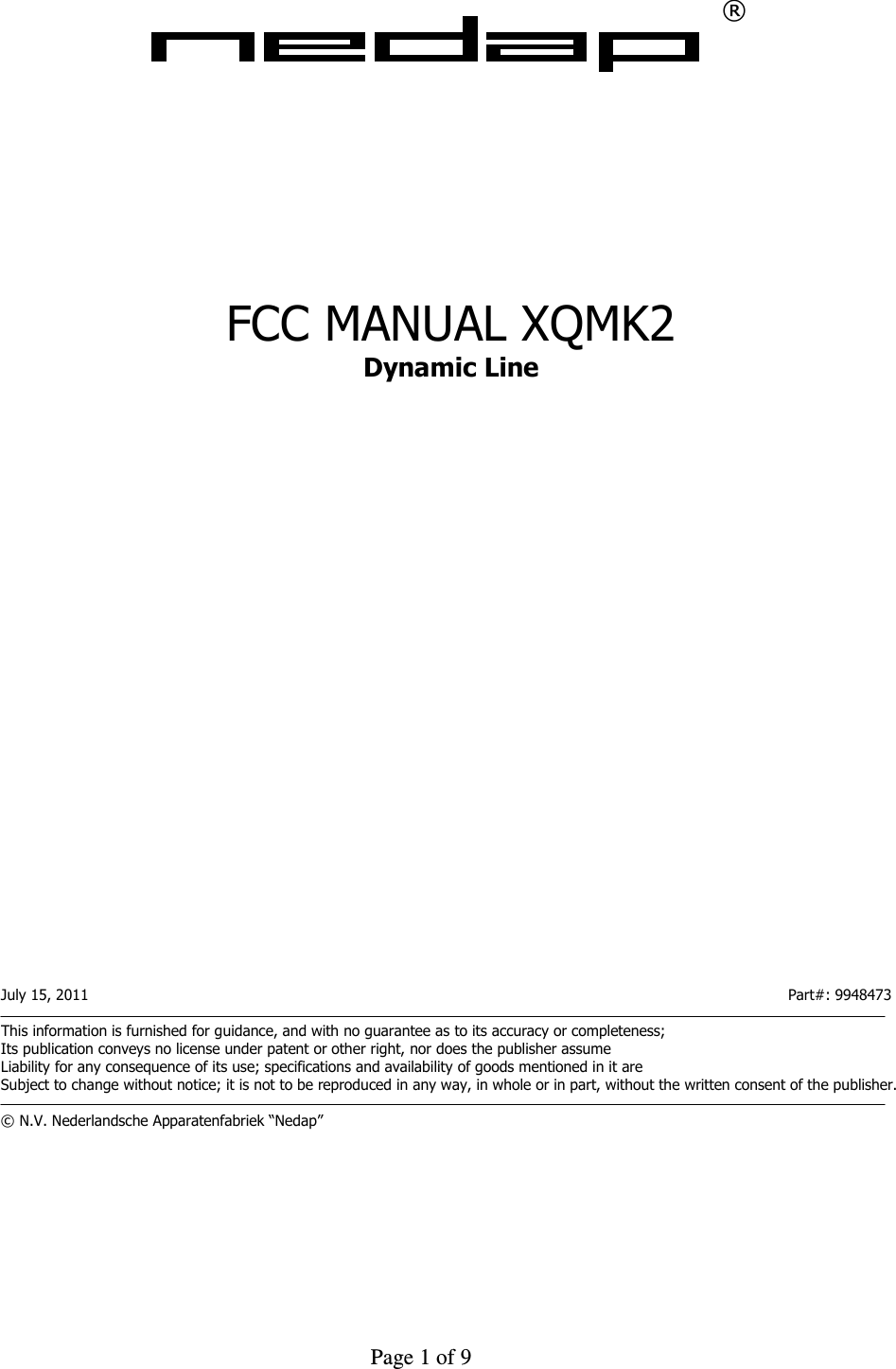
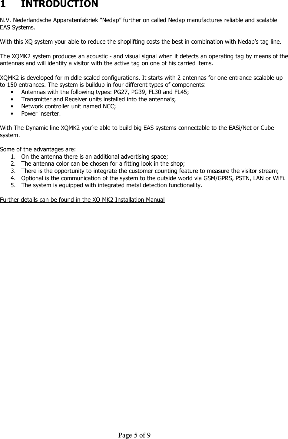
![Page 7 of 9 o Distance between two antennas when using hard tags Ø50 mm and PG39 antennas is: 2.60 m; o Distance between two antennas when using paper tags 4x4 and PG39 antennas is: 2.20 m; o Distance between an antenna and a wall, door, sliding door etc. must be at least 200 mm; o Distance between an antenna and the nearest tagged item must be at least 2000 mm. 3 Wiring diagram Schematically diagrams below shows an example of the connections between used modules. The picture shows the full configuration that can be built up. Ant.Ant.Ant.Ant.Ant. Figure 2 Example full configuration The connections for a full configuration are: 1. Datacom cable for NCC to Unit XQMK2 Connects Data communication and power from NCC [9203508] to a Unit XQMK2 Tx [8018464] or Unit XQMK2 Rx [8018472]. NOTE: The distance between the NCC and the transmitter antenna shall 4 meters or more. 2. Datacom cable for NCC to Unit XQMK2 Connects the data and power between the XQMK2 Tx or Rx Units. 3. Tx or Rx coax cable Connects the antenna input/output XQMK2 Tx [8018464] or Rx [8018472] to the EAS antenna loops PG27, PG39, FL30, FL45. 4. Rx or Tx cable for Metal detection Connects the metal detection antenna input/output from XQMK2 Tx [8018464] or Rx [8018472] to the Metal detection antenna loop PG27, PG39, FL30, FL45. 5. Cable for Customer counting and lighting unit PG27/PG39 Connects the XQMK2 Tx [8018464] or Rx [8018472]to the Customer Counter and lighting unit [7833342]. 6. Cable for Cusomer counting and lighting unit FL30/FL45 Connects the XQMK2 Tx [8018464] or Rx [8018472] to one of the Customer counter units [9923373, 9928529, 9936114, 9935207]. 7. Cable for lighting module FL30/FL45 Connects the XQMK2 Tx [8018464] or Rx [8018472] to the lighting module. 8. DC cable from Power adapter to NCC electronics Connects the Power-adapter [9651543] to the NCC main board [7824785] and carries 33V DC power. 9. Mains cable Connects the Mains power to the Power-adapter [9651543]. 10. Coax cable for GSM antenna Connects the GSM module to the GSM external antenna to contact the GSM network. 11. Datacom cables to slave NCC’s Connects a NCC with the behavior “Master” to NCC devices with the behavior “Slave”. 12. Datacom cables for system expansion Connects more antenna strings up to 16 devices with the same function as Wire 1 and 2.](https://usermanual.wiki/Nedap-N-V/XQMK2.User-manual/User-Guide-1526096-Page-7.png)