Neptune Technology Group CMIU-VZW-1 Water meter reading equipment User Manual FCC Part 15
Neptune Technology Group Inc. Water meter reading equipment FCC Part 15
Manual

2320 Presidential Drive, Suite 101, Durham, NC 27703 USA Voice: 919-381-4235 Fax: 770-831-8598
Certification Exhibit
FCC ID: P2SCMIU-VZW-1
FCC Rule Part: 15.247
ACS Project Number: 15-3049
Manufacturer: Neptune Technology Group
Model: CMIU
Manual
E-Cod
E-Cod
CELLULAR MIU INSTALLATION AND MAINTENANCE GUIDE
Celluar MIU Installation and Maintenance Guide

Cellular MIU Installation and Maintenance Guide

Copyright
This manual is an unpublished work and contains the trade secrets and confidential information of
Neptune Technology Group Inc., which are not to be divulged to third parties and may not be reproduced or transmitted in
whole or part, in any form or by any means, electronic or mechanical for any purpose, without the express written permission
of Neptune Technology Group Inc. All rights to designs or inventions disclosed herein, including the right to manufacture, are
reserved to Neptune Technology Group Inc.
The information contained in this document is subject to change without notice. Neptune reserves the right to change the
product specifications at any time without incurring any obligations.
Trademarks used in this manual
R900, ARB, ProRead, and E-Coder are registered trademarks of Neptune Technology Group Inc. Other brands or product
names are the trademarks or registered trademarks of their respective holders.
FCC Notice
This device complies with Part 15 of the FCC Rules. Operation is subject to the following two conditions:
1 This device may not cause harmful interference,
2 This device must accept any interference received, including interference that may cause undesired operation.
Any Change or modification to the product is not expressly approved by Neptune and could void the user's authority to oper-
ate the device.
This equipment complies with the FCC radiation exposure limits set forth in an uncontrolled environment.
This equipment should be installed and operated with minimum distance 20cm between the equipment and the user's body.
NOTE: This equipment has been tested and found to comply with the limits for a Class B digital device, pursuant to part 15 of
the FCC Rules. These limits are designed to provide reasonable protection against harmful interference in a residential
installation. This equipment generates, uses and can radiate radio frequency energy and, if not installed and used in accor-
dance with the instructions, may cause harmful interference to radio communications. However, there is no guarantee that
interference will not occur in a particular installation. If this equipment does cause harmful interference to radio or television
reception, which can be determined by turning the equipment off and on, the user is encouraged to try to correct the interfer-
ence by one or more of the following measures:
• Reorient or relocate the receiving antenna.
• Increase the separation between the equipment and receiver.
• Connect the equipment into an outlet on a circuit different from that to which the receiver is connected.
• Consult the dealer or an experienced radio/TV technician for help.
.
Changes or modifications not expressly approved by the party responsible for compliance could void the
user's authority to operate the equipment.
Cellular MIU Installation and Maintenance Guide
Literature No. IM CMIU 11.15
Part No. XXXXX-XXX
Neptune Technology Group Inc.
1600 Alabama Highway 229
Tallassee, AL 36078
Tel: (800) 633-8754
Fax: (334) 283-7293
Copyright © 2015
Neptune Technology Group Inc.
All Rights Reserved.

Contents
CMIU Installation and Maintenance Guide iii
1Product Description
2Specifications
Electrical Specifications. . . . . . . . . . . . . . . . . . . . . . . . . . . . . . . . . . . . . . . . . . . . . . . . . . . . . . . . . . . . . . . . . . 2
Encoder Register Interface . . . . . . . . . . . . . . . . . . . . . . . . . . . . . . . . . . . . . . . . . . . . . . . . . . . . . . . . . . . . . . . 2
Specifications - CMIU MIU . . . . . . . . . . . . . . . . . . . . . . . . . . . . . . . . . . . . . . . . . . . . . . . . . . . . . . . . . . . . . . . 2
Environmental Conditions . . . . . . . . . . . . . . . . . . . . . . . . . . . . . . . . . . . . . . . . . . . . . . . . . . . . . . . . . . . . 2
Functional Specifications . . . . . . . . . . . . . . . . . . . . . . . . . . . . . . . . . . . . . . . . . . . . . . . . . . . . . . . . . . . . . 2
3General Installation Guidelines
Tools and Materials. . . . . . . . . . . . . . . . . . . . . . . . . . . . . . . . . . . . . . . . . . . . . . . . . . . . . . . . . . . . . . . . . . . . . 3
Safety and Preliminary Checks . . . . . . . . . . . . . . . . . . . . . . . . . . . . . . . . . . . . . . . . . . . . . . . . . . . . . . . . . . . . 4
Verifying/Preparing the Encoder Register. . . . . . . . . . . . . . . . . . . . . . . . . . . . . . . . . . . . . . . . . . . . . . . . . . . . 4
Installation of a Register (Non Pre-Wired or Potted Only). . . . . . . . . . . . . . . . . . . . . . . . . . . . . . . . . . . . . . . . 5
4Wall Installation
Installing the Cellular MIU . . . . . . . . . . . . . . . . . . . . . . . . . . . . . . . . . . . . . . . . . . . . . . . . . . . . . . . . . . . . . . . . 8
Removing the Main Housing . . . . . . . . . . . . . . . . . . . . . . . . . . . . . . . . . . . . . . . . . . . . . . . . . . . . . . . . . . 8
Applying the Scotchloks. . . . . . . . . . . . . . . . . . . . . . . . . . . . . . . . . . . . . . . . . . . . . . . . . . . . . . . . . . . . . . 9
Activating and Completing the Installation . . . . . . . . . . . . . . . . . . . . . . . . . . . . . . . . . . . . . . . . . . . . . . . 10
5Contact Information
By Phone. . . . . . . . . . . . . . . . . . . . . . . . . . . . . . . . . . . . . . . . . . . . . . . . . . . . . . . . . . . . . . . . . . . . . . . . . . . . 11
By Fax . . . . . . . . . . . . . . . . . . . . . . . . . . . . . . . . . . . . . . . . . . . . . . . . . . . . . . . . . . . . . . . . . . . . . . . . . . . . . . 11
By Email . . . . . . . . . . . . . . . . . . . . . . . . . . . . . . . . . . . . . . . . . . . . . . . . . . . . . . . . . . . . . . . . . . . . . . . . . . . . 11

Notes:
Contents
iv CMIU Installation and Maintenance Guide

CMIU Installation and Maintenance Guide v
Figures
Figure Title Page
1 Cellular MIU . . . . . . . . . . . . . . . . . . . . . . . . . . . . . . . . . . . . . . . . . . . . . . . . . . . . . . . . . . . . . . . . . .1
2 Wiring a Neptune Encoder Register . . . . . . . . . . . . . . . . . . . . . . . . . . . . . . . . . . . . . . . . . . . . . . . .5
3 MIU Color Code for Wires. . . . . . . . . . . . . . . . . . . . . . . . . . . . . . . . . . . . . . . . . . . . . . . . . . . . . . . .6
4 Cable Threaded Around Strain Relief Posts . . . . . . . . . . . . . . . . . . . . . . . . . . . . . . . . . . . . . . . . . .6
5 Application of the Sealant . . . . . . . . . . . . . . . . . . . . . . . . . . . . . . . . . . . . . . . . . . . . . . . . . . . . . . . .7
6 Covering the Terminal Screws . . . . . . . . . . . . . . . . . . . . . . . . . . . . . . . . . . . . . . . . . . . . . . . . . . . .7
7 Wall MIU Main Housing. . . . . . . . . . . . . . . . . . . . . . . . . . . . . . . . . . . . . . . . . . . . . . . . . . . . . . . . . .8
8 Mounting Adapter . . . . . . . . . . . . . . . . . . . . . . . . . . . . . . . . . . . . . . . . . . . . . . . . . . . . . . . . . . . . . .8
9 Gel Cap Connections . . . . . . . . . . . . . . . . . . . . . . . . . . . . . . . . . . . . . . . . . . . . . . . . . . . . . . . . . . .9
10 MIU Color Code for Wires. . . . . . . . . . . . . . . . . . . . . . . . . . . . . . . . . . . . . . . . . . . . . . . . . . . . . . . .9
11 Cable in Back of Mounting Adapter. . . . . . . . . . . . . . . . . . . . . . . . . . . . . . . . . . . . . . . . . . . . . . . . .9
12 Cable Exit Notch . . . . . . . . . . . . . . . . . . . . . . . . . . . . . . . . . . . . . . . . . . . . . . . . . . . . . . . . . . . . . .10
13 Securing Mounting Adapter. . . . . . . . . . . . . . . . . . . . . . . . . . . . . . . . . . . . . . . . . . . . . . . . . . . . . .10
14 Activating the MIU. . . . . . . . . . . . . . . . . . . . . . . . . . . . . . . . . . . . . . . . . . . . . . . . . . . . . . . . . . . . .10

vi CMIU Installation and Maintenance Guide
Notes:
Figures

CMIU Installation and Maintenance Guide vii
Tables
Table Title Page
1 Recommended Tools . . . . . . . . . . . . . . . . . . . . . . . . . . . . . . . . . . . . . . . . . . . . . . . . . . . . . . .3
2 Recommended Materials. . . . . . . . . . . . . . . . . . . . . . . . . . . . . . . . . . . . . . . . . . . . . . . . . . . . .4

viii CMIU Installation and Maintenance Guide
Notes:
Tables
CMIU Installation and Maintenance Guide 1
1 Product Description
This section provides a general description of the Neptune Technology Group cellular
meter interface unit (subsequently referred to as CMIU).
The CMIU by Neptune is a compact electronic device that collects meter reading data
from an encoder register. It then transmits the data for collection. The collected data is
stored and downloaded into the utility billing system for processing.
The CMIU is easily installed and operates within the cellular frequencies.
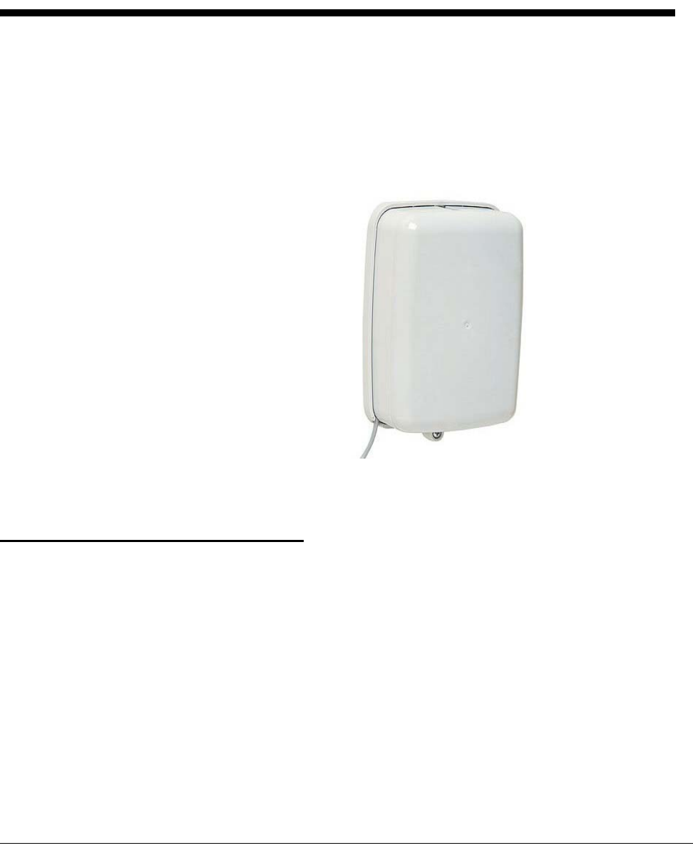
Figure 1 Cellular MIU
The CMIU does require field programming.
Product Description
CMIU Programming
The CMIU does require field programming.
Low Battery Emissions
The CMIU stops RF transmissions when the battery discharges below normal the
operating voltage.

2CMIU Installation and Maintenance Guide
2 Specifications
This section provides you with the specifications for the CMIU.
Electrical Specifications
The power is supplied by a Lithium battery.
Encoder Register Interface
Specifications - CMIU
Environmental Conditions
Functional Specifications
Supported Encoder Maximum Cable Length
Neptune ARB® V1300 feet (91 meters)
Neptune ProRead™ and E-Coder® 500 feet (152 meters)
Sensus Protocol registers 200 feet (61 meters)
1 Meets manufacturer’s published specifications for wire length between encoder and remote receptacle. The length is
based on solid three conductor wire, 22 AWG.
Operating Temperature -22° to 149°F (-30° to 65°C)
Storage Temperature -40° to 158°F (-40° to 70°C)
Operating Humidity 0 to 100% Condensing
Register Reading 8 digits
MIU ID 10 digits
CMIU Installation and Maintenance Guide 3
3 General Installation Guidelines
This section describes tools, materials, and general installation information for the CMIU.
Tools and Materials
Tables 1 and 2 show the recommended tools and materials you need to successfully install
the CMIU.
It is possible that some items do not apply to your specific installation, or the list does not contain
all required tools or materials.
Table 1 Recommended Tools
Item Description/Recommendations Use
Took Kit Contains standard tools including:
• Assorted screwdrivers
• Needle-nose pliers
• Wire stripper
• Diagonal cutters
• Electrician’s knife
• Hammer
• Crimping tool
Part # 5500-158
Perform various installation
procedures.
Magnet 6 lb. force
Part # 12287-001 Activating the MIU.

General Installation Guidelines
4CMIU Installation and Maintenance Guide
Safety and Preliminary Checks
Observe the following safety and preliminary checks before and during
each installation.
• Verify that you are at the location specified on the site work order.
• Verify that the site is safe for you and your equipment.
• Notify the customer of your presence and tell the customer that you
need access to the water meter.
• Write in the ID number(s) of the MIU you are about to install, if the
site work order does not have an MIU ID number.
• Verify that the ID number(s) matches the ID number(s) on the MIU
you are about to install, if the site worker already has an MIU ID
number.
Verifying/Preparing the Encoder Register
The CMIU is designed for use with the following encoder registers:
• ARB V
• ProRead
• ProRead AutoDetect
•E-Coder
• Competitive registers using Sensus which include: Sensus ECRII,
ICE, iPerl, OMNI and electronic register; also Hersey/Mueller
Translator, Badger ADE, and HR E|LCD.
Before installing an MIU, the encoder register must be correctly wired
and/or programmed to work with the MIU. E-Coder registers do not
require programming.
Table 2 Recommended Materials
Item Description/Recommendation Use
Cable Solid 3 conductor #22 AWG (black/
green/red) Part # 6431-352 Connect MIU to encoder
register.
Moisture Protection
Compound Novaguard sealant
Part # 96018-072 Cover exposed wires
and terminal screws on
register and MIU.
Scotchloks Part # 8138-125 Connect wall MIU or
replacement pit MIU to
encoder register.
Site Work Order Documentation provided by your
utility Receive and record
information about the
work site.
General Installation Guidelines
CMIU Installation and Maintenance Guide 5
If connecting the MIU to a new ProRead encoder register, or if a three-
conductor cable is already connected to a ProRead encoder register,
ensure that the ProRead register is programmed for three-wire mode
using the ProRead programmer and its RF/MIU 6, 8, or 10ID TDI
format. This can be accomplished through the ProRead receptacle
before removing the receptacle.
Installation of a Register (Non Pre-Wired or Potted Only)
1 Before wiring the pit encoder register, make sure the cable is long
enough. When the installation is complete, the pit lid can be
removed easily without straining the cable.
2 Use only 22 AWG cable to make the connection from the encoder
register to the MIU.
3 Remove the terminal screw cover from the encoder register.
4 Strip off ¾ inch of jacket from the cable, leaving only the three
insulated wires.
5 Take precautions not to nick or cut the insulation on the three wires,
strip off ½ inch of insulation from each of the three wires.
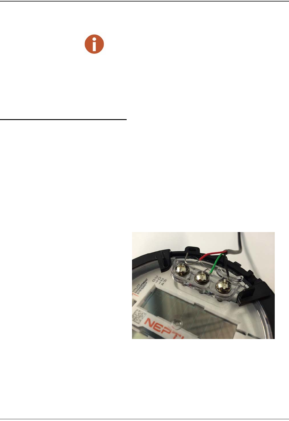
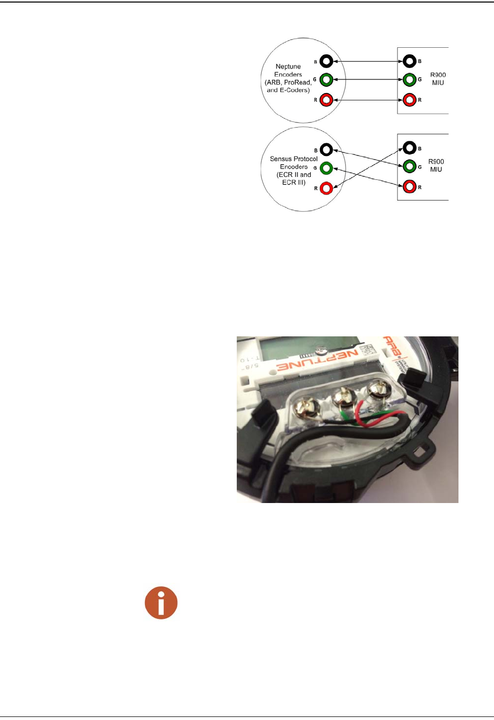
Figure 2 Wiring a Neptune Encoder Register
When a ProRead encoder register is used, the non-AutoDetect ProRead
register must be programmed for three-wire mode.
General Installation Guidelines
6CMIU Installation and Maintenance Guide
Figure 3 MIU Color Code for Wires
6 If required, connect the three conductor wires to the encoder
register’s terminals per the manufacturer’s instructions. See Figure
2 and Figure 3.
7 Thread the cable around the strain relief posts of the encoder. See
Figure 4.
Figure 4 Cable Threaded Around Strain Relief Posts
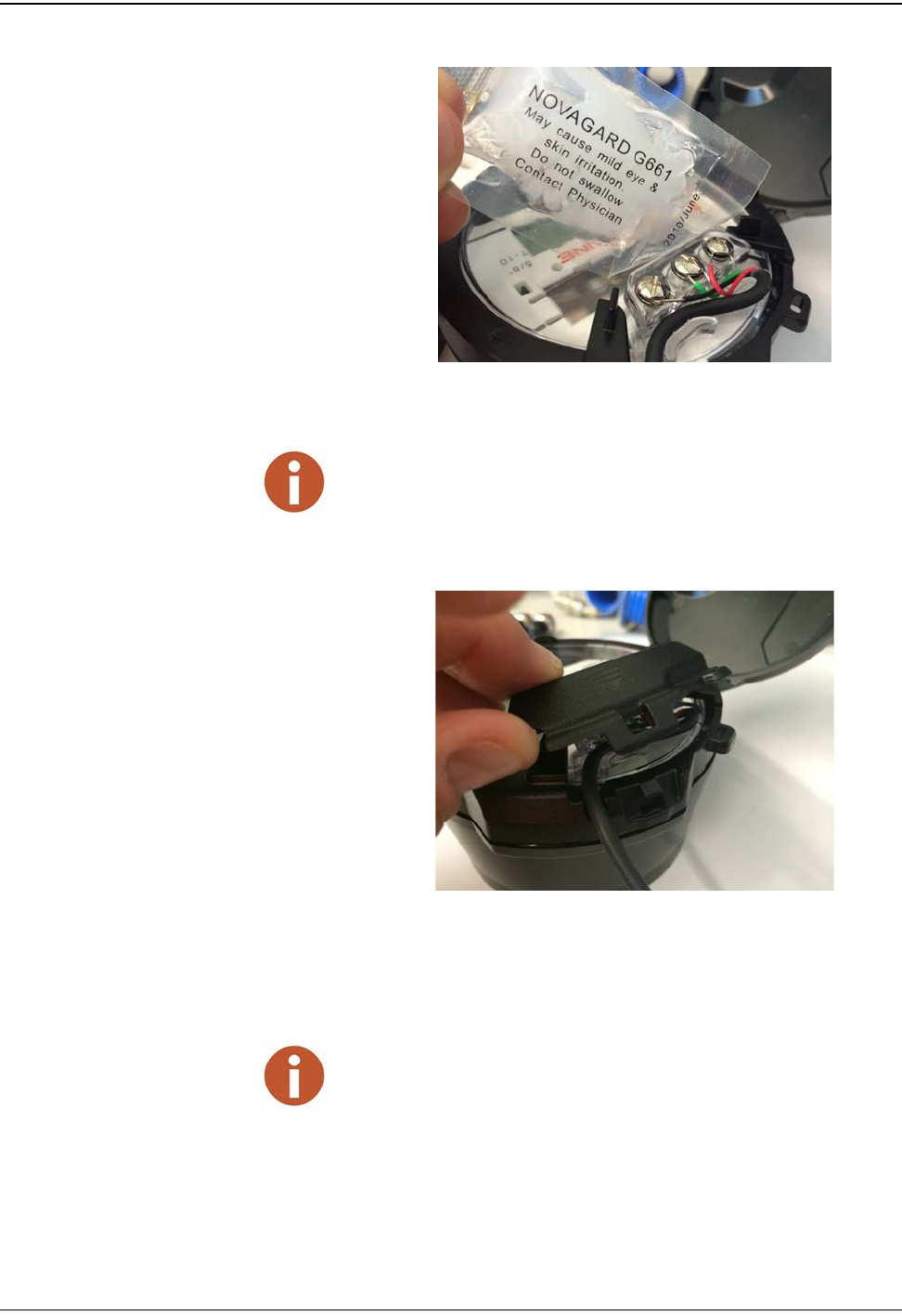
8 Apply sealant liberally and ensure that it encapsulates the terminal
screws and exposed wires. See Figure 5.
Neptune requires Novaguard G661 sealant or Dow Corning compound 4.
General Installation Guidelines
CMIU Installation and Maintenance Guide 7
Figure 5 Application of the Sealant
9 Snap the cover onto the encoder register. See Figure 6.
Figure 6 Covering the Terminal Screws
10 Run the cable to the MIU and fasten it securely.
Any leak point can cause a reading failure in a submerged meter setting.
• Do not exceed maximum cable lengths as defined in “Specifications -
CMIU” on page 2.
• If the encoder register is prewired and potted, use Scotchloks for con-
necting the register to the MIU.
8CMIU Installation and Maintenance Guide
4 Wall Installation
This chapter provides instructions for installing the CMIU.
Installing the Cellular MIU
Removing the Main Housing
Complete the following steps to install the wall MIU.
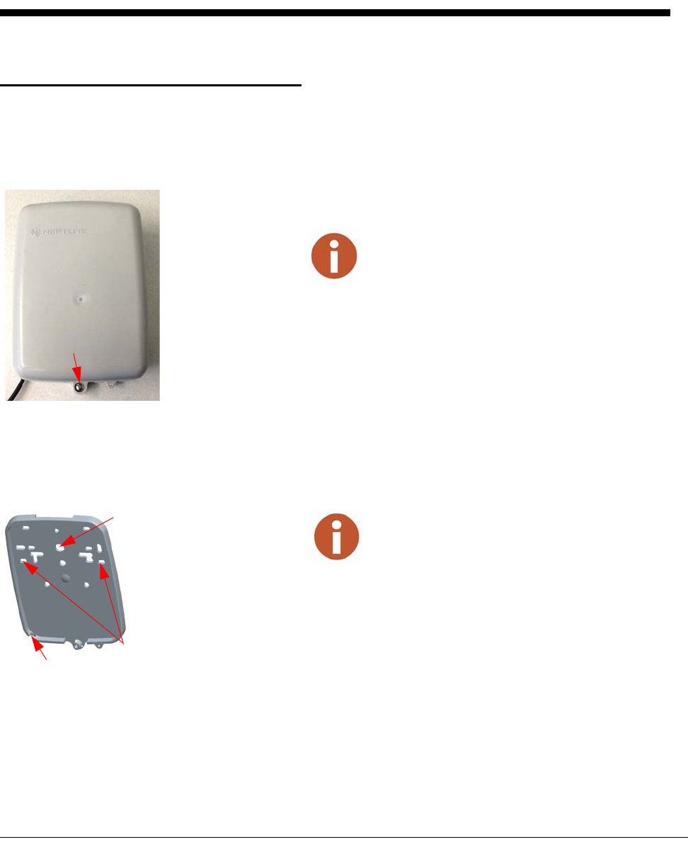
1 Remove the main housing from the mounting adapter.
Figure 7 Wall MIU Main Housing
2 StudyFigure 8 and the location requirements, then decide how to install the MIU and
mount the adapter with set screw positioned at bottom.
• The cable enters through the bottom or rear cable entry of the mounting adapter.
• When the MIU replaces a receptacle, use the appropriate holes to allow reuse of
the receptacle’s original mounting holes. SeeFigure 8.
• When mounting the MIU to a pipe, use the bolt hole for pipe mounting to bolt the
mounting adapter to a pipe clamp.
Figure 8 Mounting Adapter
The Hi-Lo fastener for securing the main MIU housing
to the adapter plate is shipped separately.
Set screw
A variety of holes in the mounting adapter allows for a
quick and easy installation.
Cable entry
Pipe clamp
Cable exit notch
Wall Installation
CMIU Installation and Maintenance Guide 9
Applying the Scotchloks
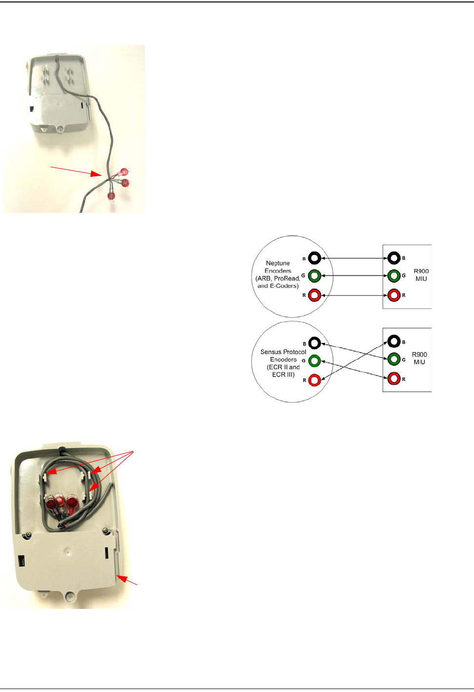
1 Using Scotchloks Gel Caps, connect the register wires to the pigtail
from the MIU. SeeFigure 9.
2 Pair the wires according to the color diagram in Figure 10.
Figure 9 Gel Cap Connections
Figure 10 MIU Color Code for Wires
3 Slide the paired wires into the grooves provided until they seat into
the back of the gel cap.
4 Using an appropriate crimping tool, firmly squeeze the gel cap to
ensure a good connection.
5 Repeat this process until all connections are complete.
6 For rear cable entry, store excess wire and Scotchloks in the hollow
cavity in the back of the MIU using the strain relief guides as shown
inFigure 11.
Figure 11 Cable in Back of Mounting Adapter
Gel caps
Strain relief guide
Cable exit notch
Wall Installation
10 CMIU Installation and Maintenance Guide
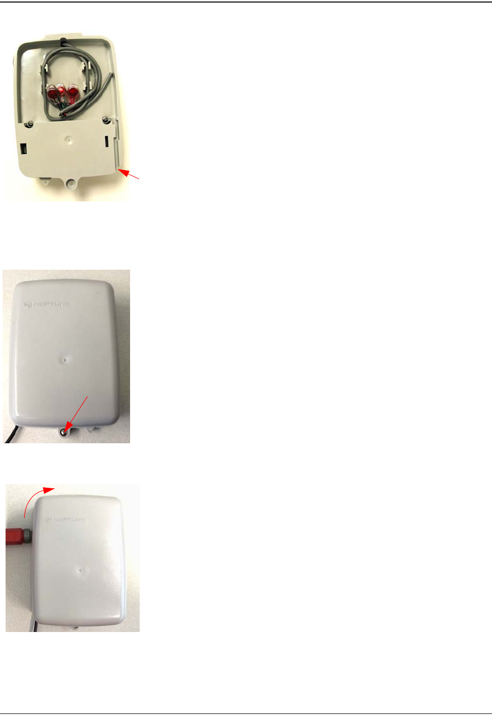
7 Continue to guide the remaining wire through the cable exit notch
at the bottom right side of the MIU as shown inFigure 12.
Figure 12 Cable Exit Notch
Activating and Completing the Installation
1 Slide the tongue on the top of the MIU into the groove on the top of
the mounting adapter.
2 Secure the MIU to the mounting adapter using the set screw.
SeeFigure 13.
Figure 13 Securing Mounting Adapter
3 Position the magnet against the left side of the MIU directly in line
with the Neptune logo, and swipe it bringing it from the side and
around the corner to the top to activate the MIU. SeeFigure 14.
Figure 14 Activating the MIU
Cable exit notch
Set screw
End swipe here

CMIU Installation and Maintenance Guide 11
5 Contact Information
Within North America, Neptune Customer Support is available Monday through Friday,
7:00 AM to 5:00 PM Eastern Standard Time by telephone, email, or fax.
By Phone
To contact Neptune Customer Support by phone, complete the following steps.
1 Call (800) 647-4832.
2 Select one of the following options:
•Press 1 if you have a Technical Support Personal Identification Number (PIN).
•Press 2 if you do not have a Technical Support PIN.
3 Enter the six-digit PIN number and press #.
4 Select one of the following options.
•Press 2 for Technical Support.
•Press 3 for maintenance contracts or renewals.
•Press 4 for Return Material Authorization (RMA) for Canadian Accounts.
You are directed to the appropriate team of Customer Support Specialists. The
specialists are dedicated to you until the issue is resolved to your satisfaction. When
you call, be prepared to give the following information.
• Your name and utility or company name.
• A description of what occurred and what you were doing at the time.
• A description of any actions taken to correct the issue.
By Fax
To contact Neptune Customer Support by fax, send a description of your problem to
(334) 283-7497. Please include on the fax cover sheet the best time of day for a Support
Specialist to contact you/
By Email
To contact Customer Support by email, send your email message to
hhsupp@neptunetg.com.

Contact Information
Notes:
12 CMIU Installation and Maintenance Guide

neptunetg.com
TAKE CONTROL
IM CMIU 11.15 Part No. XXXXX-XXX © Copyright 2015, Neptune Technology Group Inc. Neptune is a registered trademark of Neptune Technology Group Inc.
Neptune Technology Group Inc.
1600 Alabama Highway 229
Tallassee, AL 36078
USA
Tel: (800) 633-8754
Fax: (334) 283-7293
Neptune Technology Group (Canada) Ltd.
7275 West Credit Avenue
Mississauga, Ontario
L5N 5M9
Canada
Tel: (905) 858-4211
Fax: (905) 858-0428
Neptune Technology Group Inc.
Ejército Nacional No. 418
Piso 12, Desp. 1201-1202
Col. Chapultepec Morales
Delegación Miguel Hidalgo
11570 México, Distrito Federal
Tel: (525) 55203 5294 / (525) 55203 5708
Fax: (525) 55203 6503