Neptune Technology Group L900M2 900 MHz water meter transmitter. User Manual IM L900 MIU
Neptune Technology Group Inc. 900 MHz water meter transmitter. IM L900 MIU
Contents
- 1. User Manual Part A
- 2. User Manual Part B
- 3. User Manual_Part I
- 4. User Manual_Part II
User Manual Part B

This page intentionally left blank.
Chapter 4: Wall Installation
22 L900 MIU Pit and Wall Installation and Maintenance Guide
L900 MIU Pit and Wall Installation and Maintenance Guide 23
Chapter 5: Pit Installation
This chapter describes storage and unpacking instructions, preliminary tests, tools,
materials, site selection, and pit installation of the L900 MIU.
Prior to Installation
Storage
Upon receipt, inspect shipping containers and contents for damage prior to storage.
After the inspection is complete, store the cartons in a clean, dry environment.
Keep in mind that the L900 MIU has an internal battery. Storage for more than one
year can affect product life. Be sure to use a first-in first-out inventory control
system. See "Environmental Conditions" on page4
Unpacking
As with all precision electronic instruments, the L900 MIU must be handled
carefully; however, no additional special handling is required.
After unpacking the L900 MIU, inspect it for damage. If the L900 MIU appears to
be damaged or proves to be defective upon installation, notify your Neptune sales
representative. If one or more items requires reshipment, use the original cardboard
box and packing material.
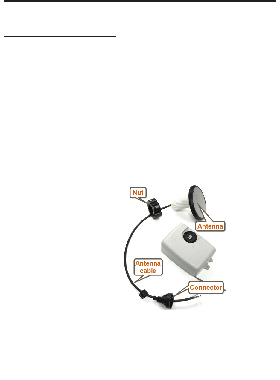
Figure 23 – L900 MIU Kit
Tools and Materials
Table 8 on page 9 and Table 9 on page 10 show the
recommended tools and materials you need to successfully install
the L900 MIU.
Some items may not apply to your specific installation, or the
list may not contain all required tools or materials.
Site Selection
Always follow your company's safety practices and
installation guidelines when installing an L900 MIU. Never
perform an installation during a lightening storm or under
excessively wet conditions.
Installation and operation in moderate temperatures increase
reliability and product life. See "L900 MIU Pit Environmental
Conditions" on page4.
Follow these guidelines when selecting a location to install the
L900 MIU.
lFor best results, select a location where there is no chance that
another object can be set over the antenna.
lAvoid installing the L900 MIU behind metal fences or walls.
lMake sure the pit location gives adequate room for installing
both the L900 MIU and the pit antenna.
For maximum performance, the flange of the pit antenna
needs to be located above the pit lid.
lFor maximum performance, Neptune recommends that pit
antennas be installed above the lid as illustrated in Figure 24.
Figure 24 – Antenna Placement for Low Traffic Areas
24 L900 MIU Pit and Wall Installation and Maintenance Guide
Chapter 5: Pit Installation

lWhen installing in a high traffic area, Neptune recommends
that the dome of the antenna be recessed in the pit lid as
shown in Figure 25.
lRecessing the installation reduces the range of the antenna.
Figure 25 – Antenna Placement for High Traffic Areas
lFor best results, Neptune recommends installing the L900 MIU
in a location that provides a direct line of site to the path of
the meter reader.
lAlthough the L900 MIU has a cable already attached (2 feet
or 6 feet), some installations can require additional cable. In
these cases, the maximum cable length between the encoder
register and L900 MIU depends on the register's manufacturer
and model. Refer to Table 11 for maximum cable lengths.
Encoder Register Maximum Cable Length
Neptune ARB V* 300 feet (91 meters)
Neptune ProRead / E-CODER 500 feet (152 meters)
Sensus Protocol Register 200 feet (61 meters)
* Meets manufacturer's published specification for wire length
between encoder and remote receptacle.
Table 11 – Cable Length and Manufacturer
L900 MIU Pit Installation
The following section describes how to install a single L900 MIU
in a pit location.
L900 MIU Pit and Wall Installation and Maintenance Guide 25
Chapter 5: Pit Installation
Select a location for the L900 MIU that meets the
recommendations in "Site Selection" on page24.
Installing the Antenna
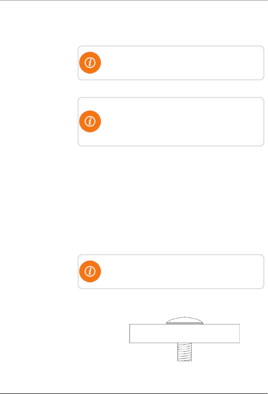
Figure 26 – Inserting the Antenna
into the Pit Lid
1. Insert the antenna cable and housing through the 1¾-
inch hole in the meter pit lid. See Figure 26.
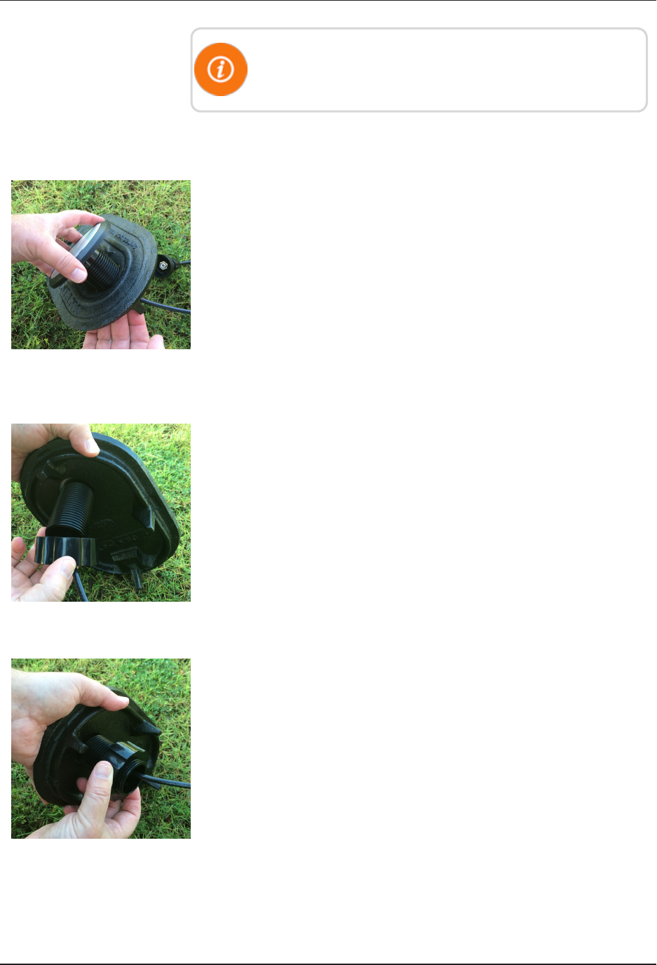
Figure 27 – Locking Nut on Antenna
2. Thread the locking nut onto the antenna (unthreaded
end towards lid). See Figure 27.
Figure 28 – Securing the Locking Nut
3. Hand tighten the nut securely to the lid. See Figure 28.
26 L900 MIU Pit and Wall Installation and Maintenance Guide
Chapter 5: Pit Installation
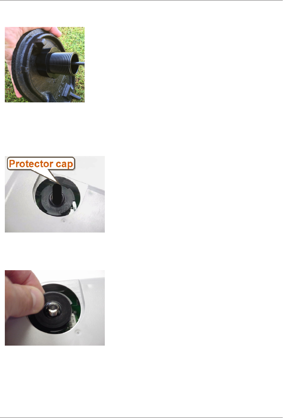
Figure 29 – Installation Completed
Figure 29 shows a completed installation of the antenna.
Begin the Installation
Complete the following steps to install the L900 MIU in a pit.
Figure 30 – Black Thread Guard from
Male F-Connector
1. Remove black plastic thread protector cap from the
male F-connector on the L900 MIU.
Figure 31 – Seating Washer
2. Place the flat black rubber washer around the male F-
connector on the L900 MIU as shown in Figure 31.
L900 MIU Pit and Wall Installation and Maintenance Guide 27
Chapter 5: Pit Installation
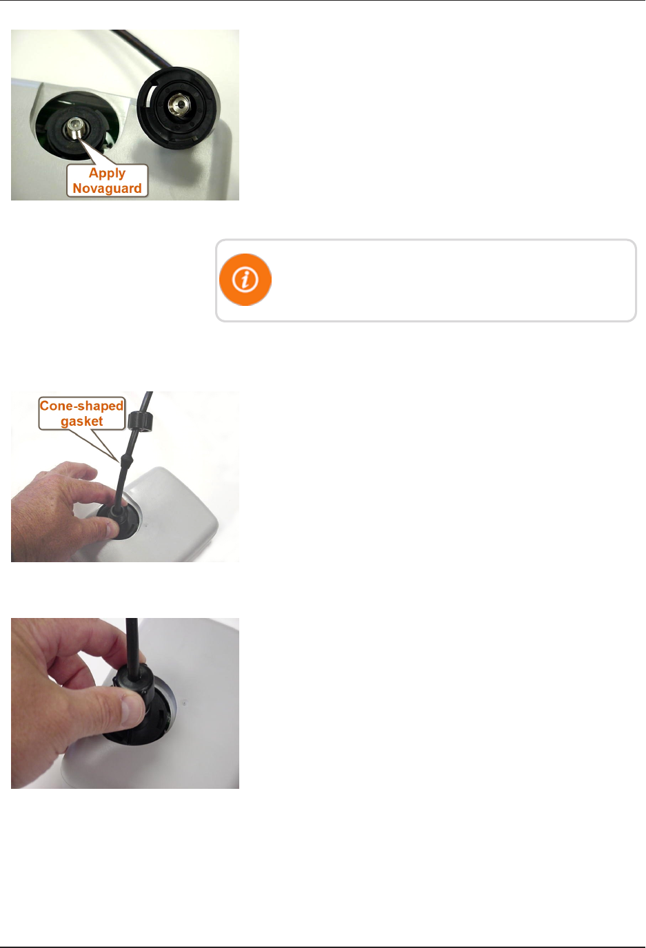
Figure 32 – Apply Novaguard
3. Apply a coating of Novaguard around the base of the
F-connector and on the flat rubber washer. See Figure
32.
4. Using a torque wrench, connect the coaxial cable
connector to the F-connector on the L900
MIU/housing, tightening it to 15 inch-pounds.
Antenna connection should have Novaguard applied
inside the connector.
Threading the F-Connector
Complete the following steps to thread the F-connector.
Figure 33 – Tightening Connector
1. Make sure the flat washer is properly seated, and then
connect the black plastic cable connector housing to
the three-lobed plastic latch plate.
2. Tighten the connector by making a ¼ turn to the right
as shown in Figure 33.
3. Slide the black cone-shaped gasket down the cable
until it seats against the connector housing.
Figure 34 – Gasket and Connector
4. Slide the black plastic female-threaded connector down
the coax cable.
5. Seat on top of cone-shaped rubber gasket and thread
onto the three-lobed plastic latch plate as shown in
Figure 34.
6. Finger-tighten the connector to depress cone-shaped
rubber gasket.
This seals the coax cable from moisture intrusion.
28 L900 MIU Pit and Wall Installation and Maintenance Guide
Chapter 5: Pit Installation
Installing the Scotchloks
Complete the following steps to install the Scotchloks.
Figure 35 – Scotchloks Connector
1. Complete steps outlined in "L900 MIU Pit Installation"
on page25 to install the L900 MIU through the lid.
2. Use 3MScotchloks type UR connector to connect the
L900 MIU wires to the encoder wires.
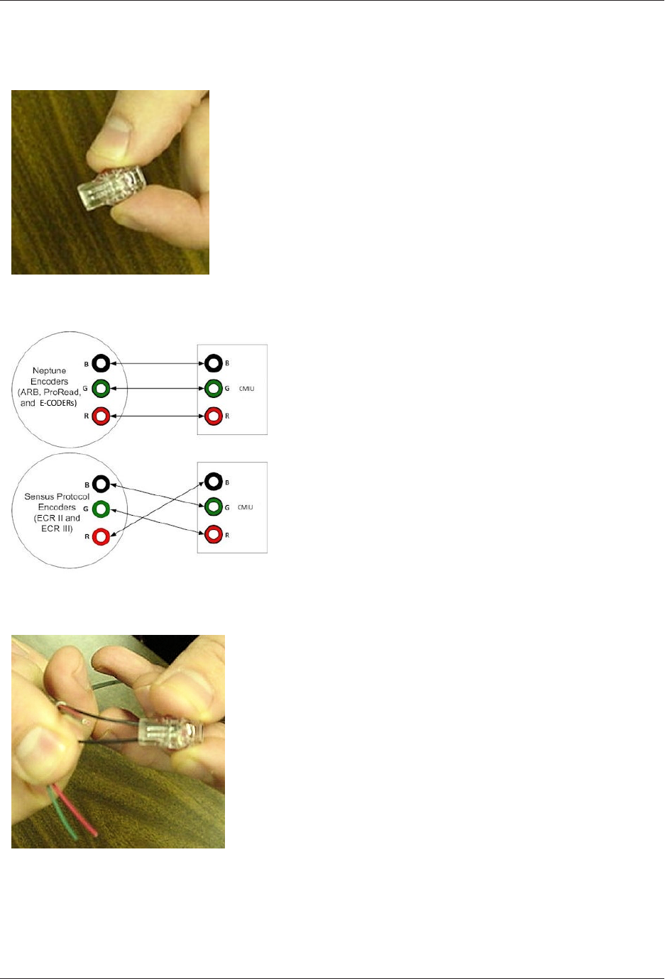
3. Hold the Scotchloks connector between the index
finger and thumb with the red cap facing down. See
Figure 35.
Figure 36 – Color Code for Wires
4. Pair the wires according to the color diagram. See Figure
36.
Figure 37 – Seating Connector Wires
5. Take a non-stripped black wire from the pigtail and a
non-stripped black wire from the L900 MIU and insert
wires into the Scotchloks connector until fully seated
in the connector. See Figure 37.
L900 MIU Pit and Wall Installation and Maintenance Guide 29
Chapter 5: Pit Installation
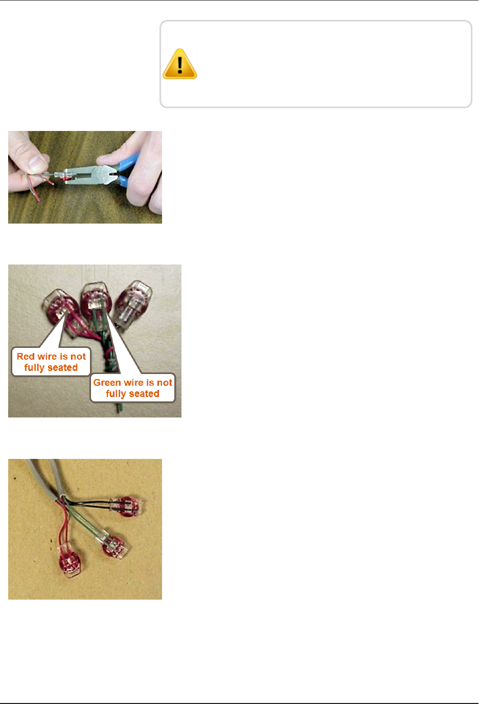
Do not strip colored insulation from wires, or strip and
twist bare wires prior to inserting in a connector. Insert
insulated colored wires directly into the Scotchloks
connector.
Figure 38 – URCrimping Tool
6. Place the connector (red cap side down) between the
jaws of the UR crimping tool as shown in Figure 38.
Figure 39 – Improper Connections
7. Check to ensure the wires are still fully seated before
crimping the connector. Figure 39 illustrates improper
connections due to wires not fully seated.
Figure 40 – Three Color Wires
Connected
8. Squeeze the connector firmly with the proper crimping
tool until you hear a pop and gel leaks out of the end of
the connector.
9. Repeat steps two through seven for each color wire. See
Figure 40.
10. After all three color wires have been connected, go to
"Wall Installation" on page15 to ensure proper
connections and the L900 MIU is functioning properly.
30 L900 MIU Pit and Wall Installation and Maintenance Guide
Chapter 5: Pit Installation
Connecting the Splice Tube
To finish the installation of the Scotchloks, complete the
following steps to install the connector king splice tube.
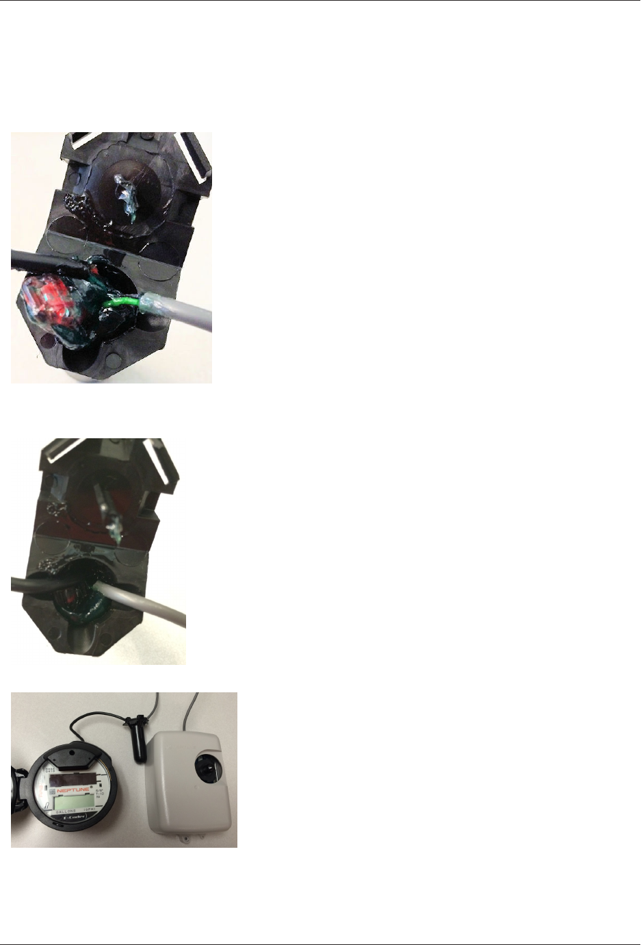
Figure 41 – Splice Tube
1. Take all three connected Scotchloks and push into the
splice tube until fully encapsulated by the silicone
grease. See Figure 41
Figure 42 – Gray Wire in Slots
2. Separate each gray wire and place in the slots on each
side as shown in Figure 42.
Figure 43 – Cover in Place
3. Snap cover closed to finish the installation as shown in
Figure 43.
L900 MIU Pit and Wall Installation and Maintenance Guide 31
Chapter 5: Pit Installation
Tying the Cable and Magnet Swiping the L900 MIU
Complete the following steps to tie the cable and magnet swipe
the .L900 MIU.
1. Place the L900 MIU in the pit location using the
following suggestions.
lIn a shallow pit application, you can place the L900
MIU beside the meter.
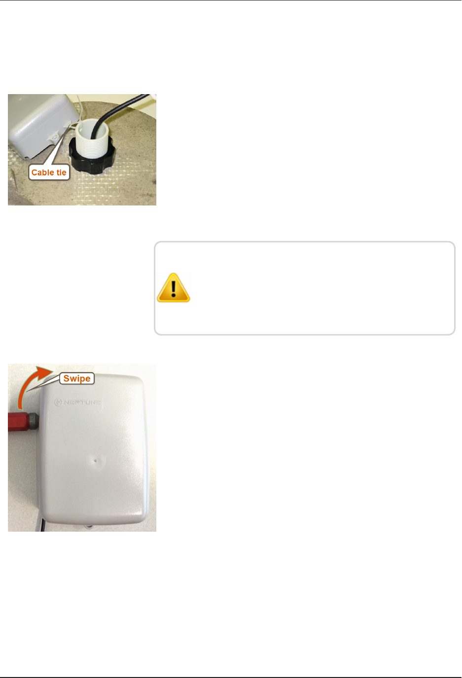
lIn deep pit applications, use a cable tie to suspend the
L900 MIU from the antenna shaft, as shown in Figure
44.
Figure 44 – L900 MIU Attached to Antenna
Be careful not to lodge the L900 MIU between the meter
box and any components inside the box.
Make sure the L900 MIU is placed in such a way that it
does not lodge itself when the pit lid is removed.
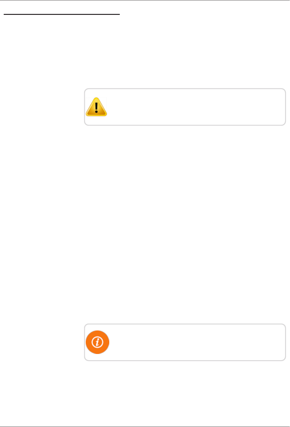
Figure 45 – Magnet Swipe the L900
MIU
2. Swipe the L900 MIU with a magnet.
lPosition the magnet against the left side of the L900
MIU directly in line with the Neptune logo.
lMove the magnet up and over the top left corner of
the L900 MIU. See Figure 45.
32 L900 MIU Pit and Wall Installation and Maintenance Guide
Chapter 5: Pit Installation
Testing the Installation
If the L900 MIU is connected to an E-CODER register or another
register with an eight-digit output, the L900 MIU will transmit an
eight-digit read. For example, read 12345678 (E-CODER or other
eight-digit register output).
To test the installation, complete the following steps.
To avoid RF signal saturation of the HHU, position yourself at
least two to three feet from the L900 MIU.
1. Power up the HHU test device and start the testing programs
provided.
2. When the L900 MIU is installed correctly, its ID number(s)
and meter reading(s) appear on the display of the HHU. Verify
the correct meter reading(s) by comparing it to the meter’s dial.
If the reading(s) is the same, proceed to the next section.
3. If a meter reading does not appear on the HHU display, or the
meter reading in the HHU display is not the same as the
reading on the meter’s dial:
lMagnet swipe the L900 MIU using the magnet.
lVerify all electrical connections.
lTest the installation again.
4. If a ProRead encoder register is used:
lEnsure the unit is programmed in three-wire mode.
lVerify all electrical connections.
lMagnet swipe the L900 MIU. (See Step 1.)
If a problem still exists, contact your Neptune sales
representative.
L900 MIU Pit and Wall Installation and Maintenance Guide 33
Chapter 5: Pit Installation

This page intentionally left blank.
Chapter 5: Pit Installation
34 L900 MIU Pit and Wall Installation and Maintenance Guide
L900 MIU Pit and Wall Installation and Maintenance Guide 35
Chapter 6: Data Logging Extraction
About Data Logging
The L900 MIU is capable of storing interval data for data logging. The L900 MIU
is activated using the Trimble®Nomad®and R900®Belt Clip Transceiver
(R900 BCT) and is explained in more detail in the following section.
The L900 MIU stores consumption in hourly intervals for a rolling total of 96 days.
This is equal to 2,304 hourly intervals of consumption. The data logging data is
extracted through RF activation. The RF activation allows the utility workers to
visit the location and extract the data without physically interacting with the meter
itself. This limits the worker’s exposure to animals or other dangerous situations.
The extraction process, once started, takes approximately 30 seconds. The
activation is done through the HHU connected to the R900 BCT via Bluetooth.
The activation signal is sent by the R900 BCT to the L900 MIU which in turn
sends the data intervals to the R900 BCT and are saved in the HHU.
Accessing Data Logging
Complete the following steps for data logging.
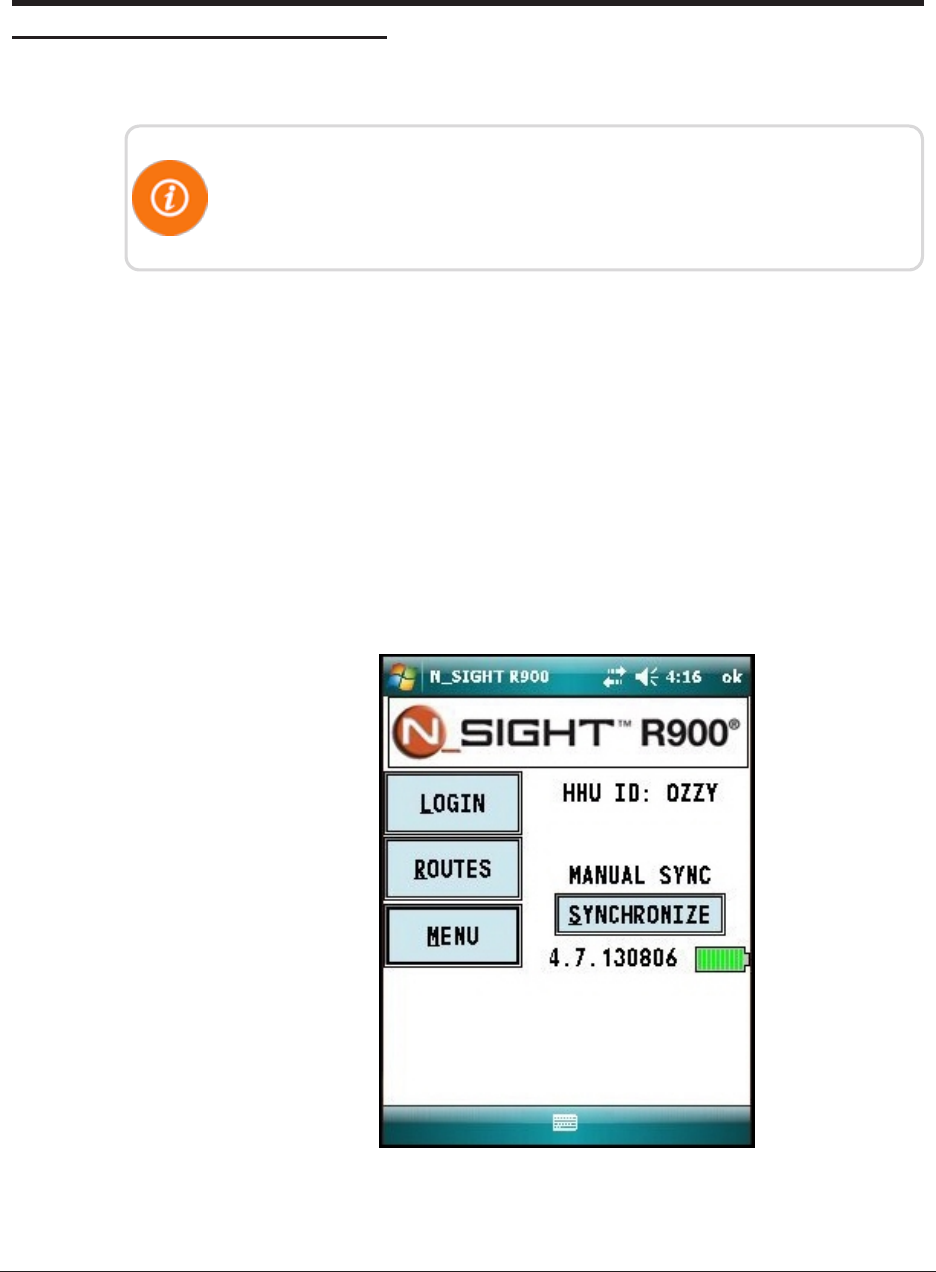
1. From the host software home screen on the HHU, click MENU. See Figure 46.
Figure 46 – HHU Home Screen
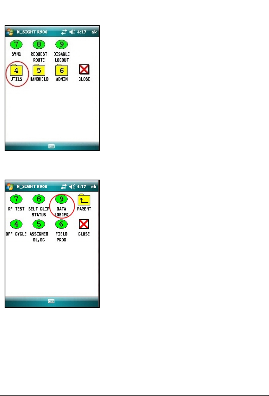
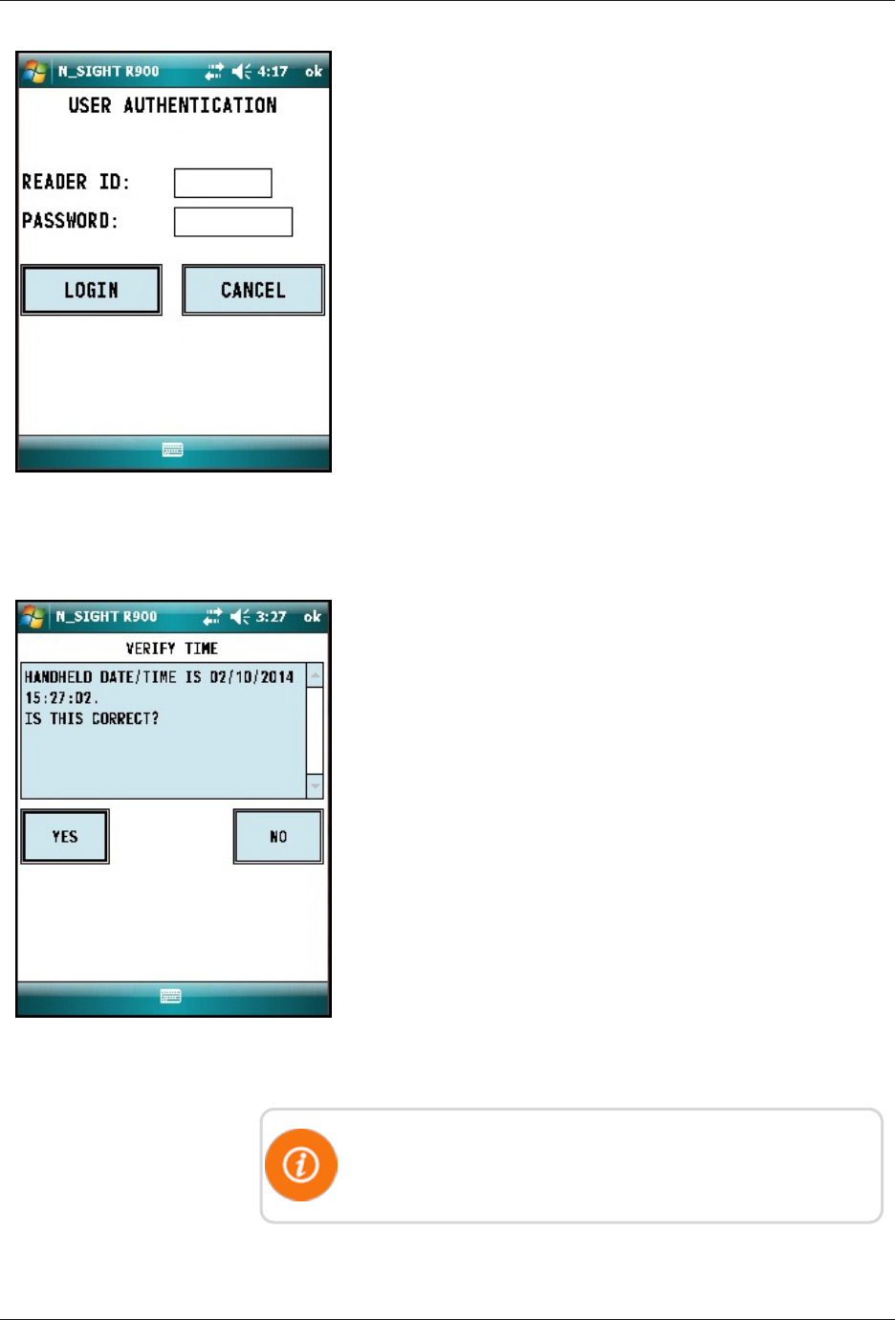
Figure 49 – Reader ID Input
4. Type your reader ID and password (if applicable) for the
host software. Click LOGIN. See Figure 49.
Initializing the Data Logger
Figure 50 – HHU Time
Confirmation
1. Verify the time is correct, and click YES. See Figure 50.
The HHU must be synchronized prior to data logging in order
to set the clock.
L900 MIU Pit and Wall Installation and Maintenance Guide 37
Chapter 6: Data Logging Extraction
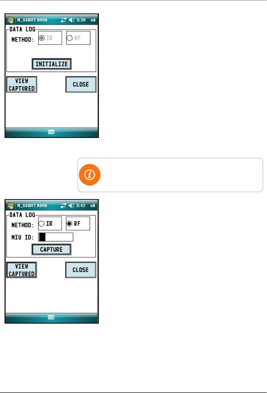
Figure 51 – Initialize RF Device
2. The Initialize Device screen appears if you are not
connected or you are not in range of your R900 BCT. Click
INITIALIZE. See Figure 51.
You must initialize the R900 BCT each time you attempt to
data log.
Figure 52 – L900 MIU ID Entry
3. Select RF and type the L900 MIU ID. See Figure 52.
38 L900 MIU Pit and Wall Installation and Maintenance Guide
Chapter 6: Data Logging Extraction
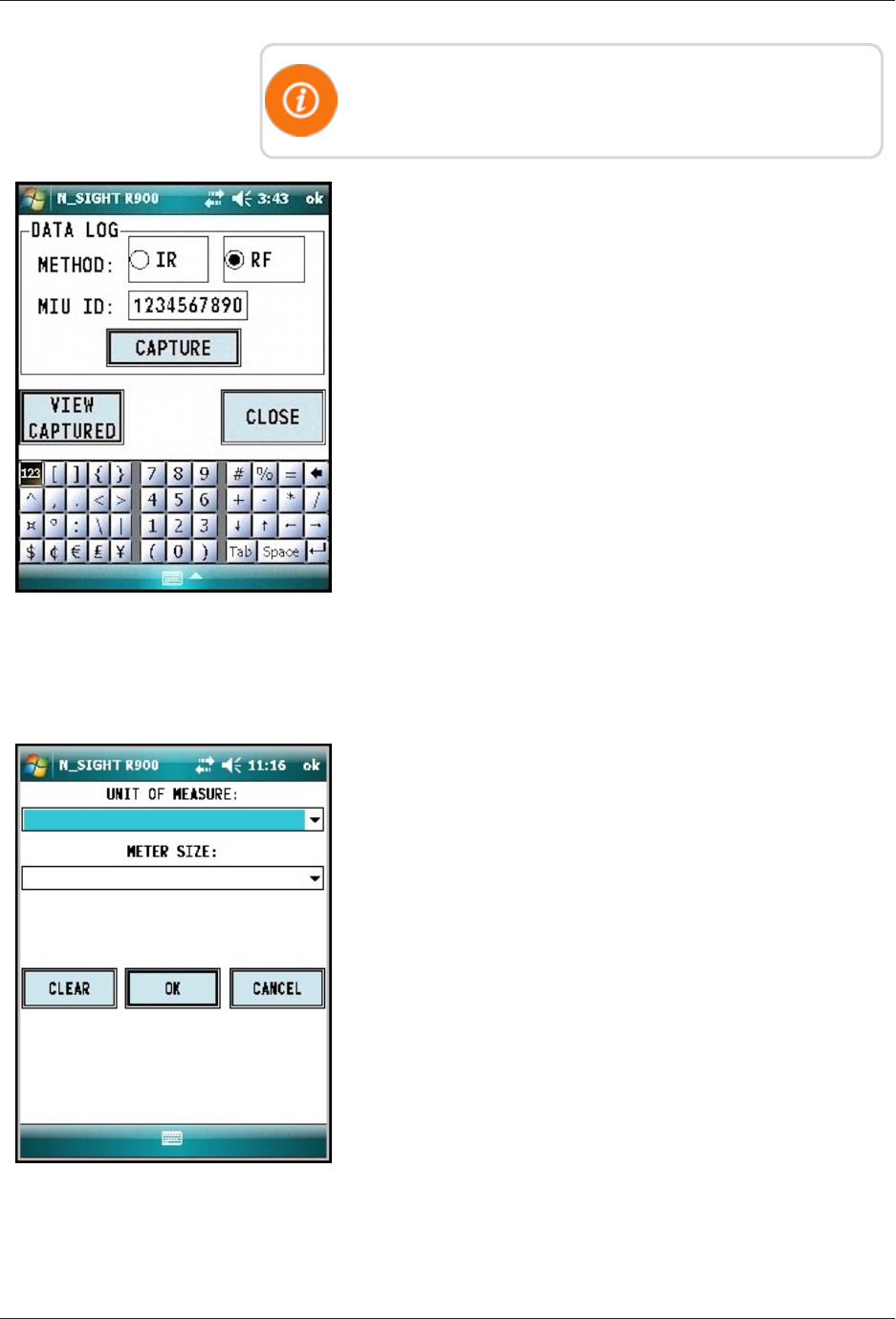
You can type the L900 MIU ID with the number pad keys or
expand the on-screen keyboard.
Figure 53 – Capture Button
4. After you type the L900 MIU ID, click CAPTURE. See
Figure 53.
Figure 54 – Meter Size Selection
5. You are prompted to provide meter size and unit of measure.
You can type this information now and click OK or after
the data logging has completed. See Figure 54.
L900 MIU Pit and Wall Installation and Maintenance Guide 39
Chapter 6: Data Logging Extraction
Initiating RF-Activated Data Logging
Complete the following steps to initiate RF-activiated data
logging.
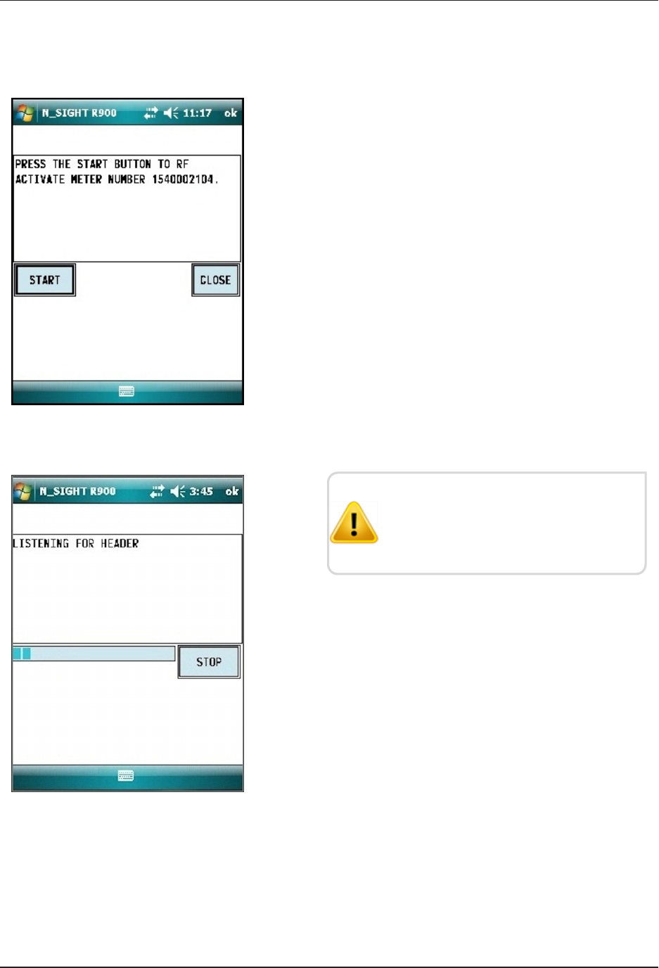
Figure 55 – Start Button
1. Click START to initiate RF-activated data logging. See
Figure 55.
Figure 56 – Listening for Data
The R900 BCT activates the L900 MIU
and listens for the data logger to start
transmitting. See Figure 56.
40 L900 MIU Pit and Wall Installation and Maintenance Guide
Chapter 6: Data Logging Extraction
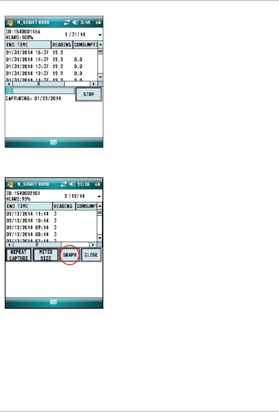
Figure 57 – Receiving Data
The data appears on the screen. See Figure 12.
Figure 58 – Graph Button
1. After the data logging process is completed, choose the
meter size (see Step 5 on page 33).
2. Click GRAPH (see Figure 56) to display the data in a
graph. Examples of graphs are shown in Figure 59 on the
next page.
The HHU processes and saves the data. After closing the
data logging screen, the unit performs a backup.
Sample Data Logging Graphs
The following are two examples of the graphs that can be produced with data
logging.
L900 MIU Pit and Wall Installation and Maintenance Guide 41
Chapter 6: Data Logging Extraction
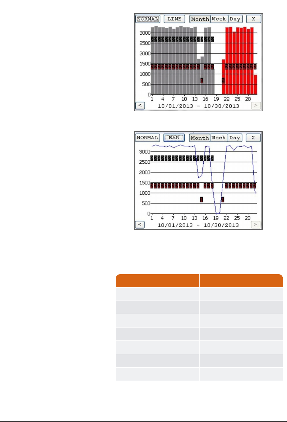
Figure 59 – Examples of Data Logging Graphs
Color Code Description
1 red Intermittent Leak
2 red Continuous Leak
1 gray Minor Backflow
2 gray Major Backflow
Blue bars No Flags
Red bars Leak
Gray bars * Backflow
* If the Backflow flag and the Leak flag appear at the same time,
Backflow (Gray bars) has precedence over Leak.
Table 12 – Data Logging Graph Legend
42 L900 MIU Pit and Wall Installation and Maintenance Guide
Chapter 6: Data Logging Extraction
Off-Cycle Data Extraction
Off-cycle reads are 96 days of daily reads. These are to allow
utilities to retrieve move-out reads or monitor vacant usage to
prevent theft.
To navigate to off cycle, complete the following steps.
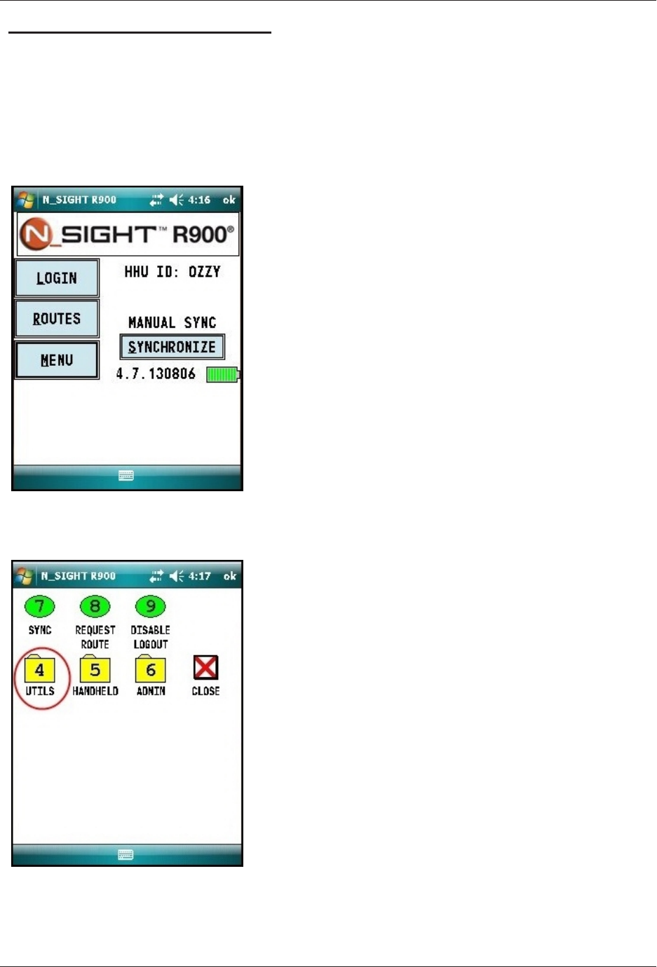
Figure 60 – HHU Home Screen
1. From the host software home screen on the HHU, click
MENU. See Figure 60.
Figure 61 – HHU Menu Screen
2. From the HHU Menu screen, click UTILS (option 4). See
Figure 61.
L900 MIU Pit and Wall Installation and Maintenance Guide 43
Chapter 6: Data Logging Extraction
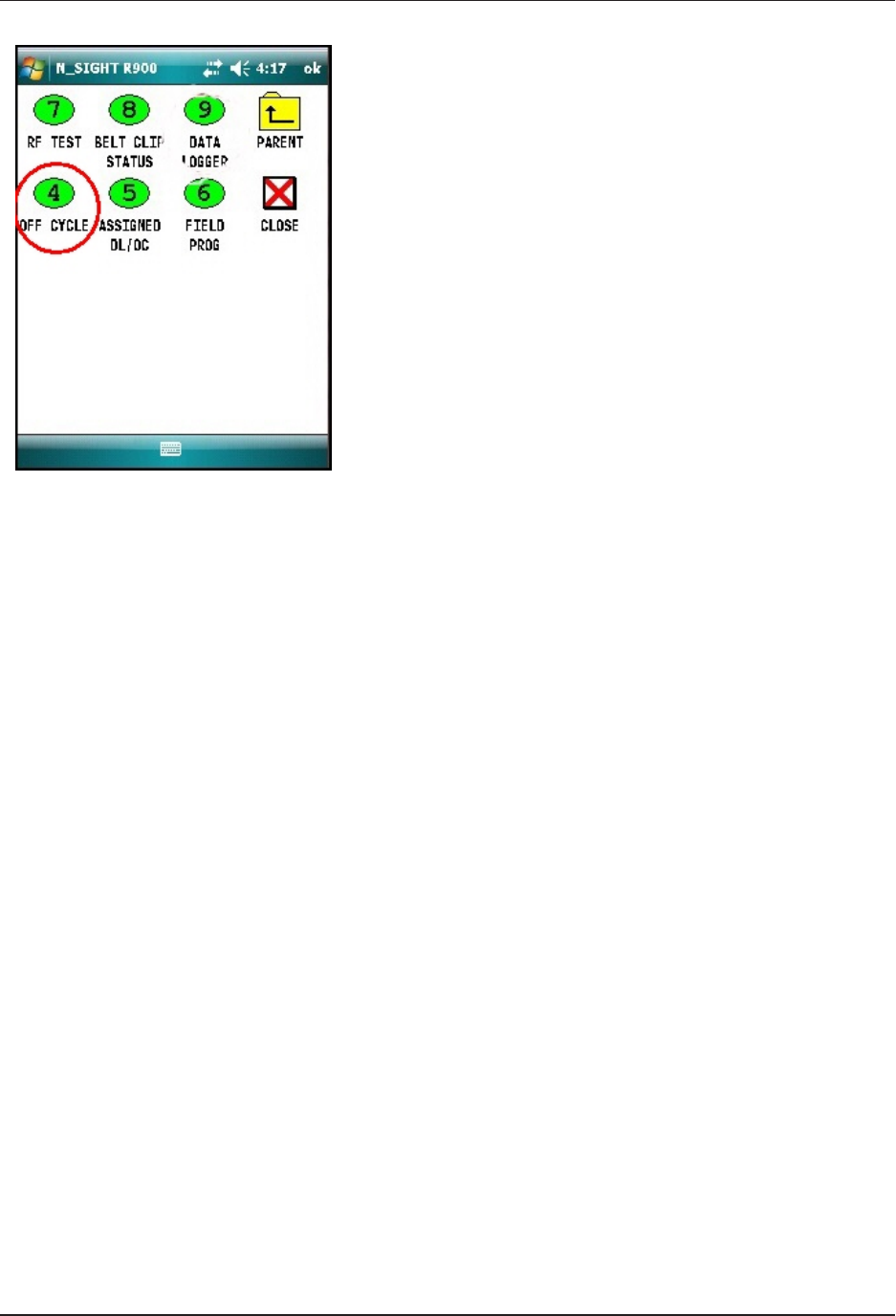
Figure 62 – Off-Cycle Option
3. Click OFF CYCLE (option 4). See Figure 62.
4. Type the read ID and/or the password.
5. Click LOGIN.
6. Confirm date and time are correct.
7. Click YES.
R900 Belt Clip Transceiver
To pair with R900 BCT, complete the following steps.
1. Change date if you have a specific day to target.
2. Click INITALIZE to pair with R900 BCT.
3. Type the L900 MIU ID.
4. Click CAPTURE.
The reads come in just like the data logger reads. The data
logger has 96 days of hourly reads and off cycle has 96 days
of daily reads.
44 L900 MIU Pit and Wall Installation and Maintenance Guide
Chapter 6: Data Logging Extraction
L900 MIU Pit and Wall Installation and Maintenance Guide 45
Chapter 7: Maintenance and Troubleshooting
This chapter takes you through maintenance and troubleshooting procedures for the
L900 MIU.
Six- and Four-Wheel Encoders
Six-Wheel Encoders Normal Operation
If the odometer reads 123456, the display should show 1 2 3 4 5 5 0 0.
The sixth digit displayed is a five if the last digit on the odometer is five through
nine. The sixth digit is a zero if the last digit on the odometer is zero through
four. The L900 MIU adds an additional two zeros on the end to provide an eight-
digit reading to the host software.
Four-Wheel Encoders Normal Operation
If the odometer reads 1234, the display should show 1 2 3 4 0 0 0 0.
The L900 MIU adds an additional four zeros on the end to provide an eight-digit
reading to the host software.

Troubleshooting
This section provides examples of possible reading values, and what they indicate.
Reading
Value Definition Troubleshooting
:::::::: Failure to retrieve reading lUsually indicates a cut wire. Check the
connection between the register and L900
MIU.
lIf using a non-autodetect ProRead
register, verify that it has been
programmed for three-wire mode.
???????? lIndicates an ambiguous, bad read
lReplaces -------- and HHHHHHHH
Table 13 – Examples of Reading Values
Replacement Parts
Table 14 lists the available replacement parts for the L900 MIU.
Part Name Part Number
Solid 3 Conductor Wire, 22 awg (1000 ft.) 6431-352
Dow Corning #4 compound (5.3 oz tube) 96018-064
GE Novaguard (4cc packet) 96018-072
Scotchloks (UG) 8138-125
Mounting Adapter for ProRead Register 12539-001
Mounting Bracket for E-CODER Register 13443-000
Fastener Screw 8328-302
Magnet 12287-001
Antenna 12527-000
Flat Washers 8340-054
Table 14 – Available Replacement Parts
46 L900 MIU Pit and Wall Installation and Maintenance Guide
Chapter 7: Maintenance and Troubleshooting

L900 MIU Pit and Wall Installation and Maintenance Guide 47
Chapter 8: Contact Information
Within North America, Neptune Customer Support is available Monday
throughFriday, 7:00 AM to 5:00 PM Central Standard Time by telephone, email,
or fax.
By Phone
To contact Neptune Customer Support by phone, complete the following steps.
1. Call (800) 647-4832.
2. Select one of the following options.
lPress 1if you have a Technical Support Personal Identification Number (PIN).
lPress 2if you do not have a Technical Support PIN.
3. Enter the six-digit PIN number and press #.
4. Select one of the following options.
lPress 2for Technical Support.
lPress 3for maintenance contracts or renewals.
lPress 4for Return Material Authorization (RMA) for Canadian Accounts.
You are directed to the appropriate team of Customer Support Specialists. The
specialists are dedicated to you until the issue is resolved to your satisfaction.
When you call, be prepared to give the following information.
lYour name and utility or company name.
lA description of what occurred and what you were doing at the time.
lA description of any actions taken to correct the issue.
By Fax
To contact Neptune Customer Support by fax, send a description of your problem
to (334) 283-7497. Please include on the fax cover sheet the best time of day for a
Support Specialist to contact you.
By Email
To contact Customer Support by email, send your email message to
hhsupp@neptunetg.com.

This page intentionally left blank.
Chapter 8: Contact Information
48 L900 MIU Pit and Wall Installation and Maintenance Guide

Glossary
A
antenna (pit)
L900 MIU antenna used for pit installations.
C
conical-shaped gasket
Cone-shaped rubber gasket on antenna cable used to seal cable at top of connector
housing.
connector housing
Black plastic 1/4-turn connector for waterproofing antenna cable connection to L900 MIU pit.
connector nut
Black plastic nut used to depress conical-shaped gasket and seal antenna cable at the top of
connector housing.
F
flat washer
Washer used to seal cable connector housing to L900 MIU pit.
L
L900 MIU
Term used for meter interface unit.
LoRa
Term that stands for Long Range; a technology that uses unlicensed spectrum below 1GHz
along with a form of direct sequence spread spectrum modulation that provides signal
detection below the noise level.
L900 MIU Pit and Wall Installation and Maintenance Guide 49

M
main housing
Main body of the L900 MIU that attaches to the mounting adapter.
main housing fastener screw
Set screw (Hi-Lo fastener) that holds the main housing to the mounting adapter.
maximum cable length
Length set by the manufacturer for the wire between the encoder and the remote receptacle.
The specifications for this length are based on a solid 3-conductor wire.
MIU
See L900 MIU.
mounting adapter
Back plate of the L900 MIU that is attached to the wall.
N
Novaguard sealant
Moisture protection compound.
P
potting
Covering of an electronic or electrical device to protect it from the surrounding environment.
R
register read time
Default time for all registers is 15 minutes. Custom time is not available.
50 L900 MIU Pit and Wall Installation and Maintenance Guide
Glossary

S
Scotchloks
Gel caps used to connect the register to the pigtail from the L900 MIU.
seal wire
Wire inserted into the seat holes adjacent to the main housing fastner screw. This seal must
be broken to remove the main housing from the mounting adapter.
serial number
Unique identification number given to each L900 MIU at the factory. Custom serial numbers
are not available.
splice tube
Device used to join two pieces of wire.
strain relief posts
Posts located on the encoder register and the back of the main L900 MIU housing.
T
terminal screw
Screws on the encoder register face that are used to connect and anchor the three (3)
conductor wire to the register.
terminal screw cover
Plastic cover on the encoder register that protects the terminal screws and exposed wires.
transmission time
Time between L900 MIU transmissions. The default is approximately fourteen (14) seconds.
Custom time is not available.
L900 MIU Pit and Wall Installation and Maintenance Guide 51
Glossary

This page intentionally left blank.
52 L900 MIU Pit and Wall Installation and Maintenance Guide

A
access
data loggng 35
HHU home screen 35
activate
L900 MIU 20, 35
with magnet 32
with Nomad 35
active L900 MIU 9
adapter 20
antenna
cable 26
shaft 32
B
battery 3, 15
black cone-shaped gasket 28
C
cable 3, 10
22 AWG 4, 11
exit notch 19
maximum length 3
coaxial cable 28
color diagram, wire 29
conditions, functional 4
conductor wire 4, 12
connector
female-threaded 28
housing 28
Scotchloks 29
contact information 47
by email 47
by fax 47
by phone 47
crimping tool 9, 30
D
data logging 35
extraction 35
graphs 41
RF activated 40
dimensions 4, 6
E
E-CODER 4, 11
electrical specifications 3
encoder register interface 3
encoders
four wheel 45
six wheel 45
environmental conditions 4
extraction
data logging 35
off-cycle data 43
L900 MIU Pit and Wall Installation and Maintenance Guide 53
Index

Index
F
FCC 3
frequency hopping 1
functional conditions 4
G
gasket 28
gel cap 19
gel caps, Scotchloks 18
graphs, data logging 41
H
HHU menu screen 36
high traffic 25
I
installation guidelines 9
L
L900 MIU 9
product description 1
specifications 3
latch plate 28
locking nut 26
LoRa 1, 3
M
magnet 9, 36-38
magnet (illus) 20, 32
maintenance 45
materials 9
mounting adapter 17
N
Novaguard sealant 10, 28
O
odometer 45
on-screen keyboard 39
operating humidity 4, 6
P
pipe clamp 18
pit antenna 24
preliminary checks 10
prewired 14
product description 1
ProRead 4, 10
R
recommended materials 10
recommended tools 9
register
install 11
potted only 11
relief guides 19
54 L900 MIU Pit and Wall Installation and Maintenance
Guide

Index
S
safety
checks 10
practices 16, 24
Scotchloks 10, 14, 19, 29
sealant 13
set screw 20
site selection 16
specifications 3
electrical 3
environmental 4
functional 4
transmitter 3
splice tube 31
spread spectrum 1
storage 15
strain relief posts 13
swipe, L900 MIU with magnet 20, 32
T
temperature
operating 4, 6
storage 4, 6, 15
terminal screw 11
tool kit 9
tools 9, 15
transmitter specifications 3
troubleshooting 45
W
weight 4
wires, color-coded diagram 29
L900 MIU Pit and Wall Installation and Maintenance Guide 55

This page intentionally left blank.
56 L900 MIU Pit and Wall Installation and Maintenance Guide
Index

Neptune Technology Group Inc.
1600 Alabama Highway 229
Tallassee, AL 36078
USA
Tel: (800) 633-8754
Fax: (334) 283-7293
Neptune Technology Group (Canada) Ltd.
7275 West Credit Avenue
Mississauga, Ontario
L5N 5M9
Canada
Tel: (905) 858-4211
Fax: (905) 858-0428
Neptune Technology Group Inc.
Ejèrcito Nacional No. 418
Piso 12, Desp. 1201-1202
Col. Chapultepec Morales
Delegación Miguel Hidalgo
11570 Mèxico, Distrito Federal
T: (525) 55203 5294 /(525) 55203 5708
IM L900 MIU 01.18 Part No. 13381-001 © Copyright 2017 - 2018, Neptune Technology Group Inc. Neptune is a registered trademark of Neptune Technology Group Inc.