Neptune Technology Group L900M2 900 MHz water meter transmitter. User Manual IM L900 MIU
Neptune Technology Group Inc. 900 MHz water meter transmitter. IM L900 MIU
Contents
- 1. User Manual Part A
- 2. User Manual Part B
- 3. User Manual_Part I
- 4. User Manual_Part II
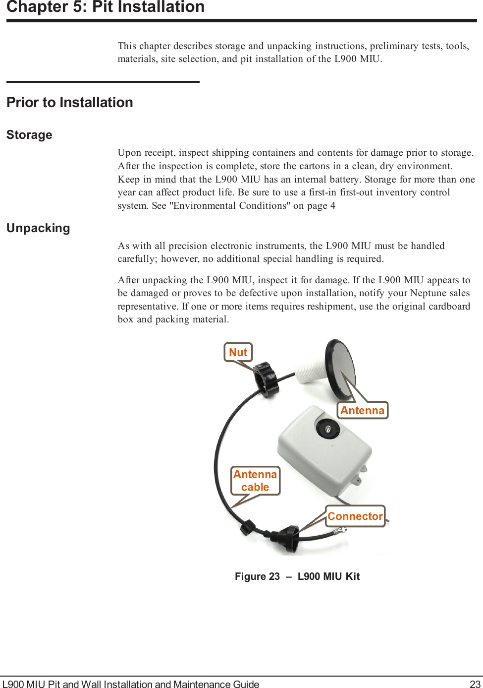
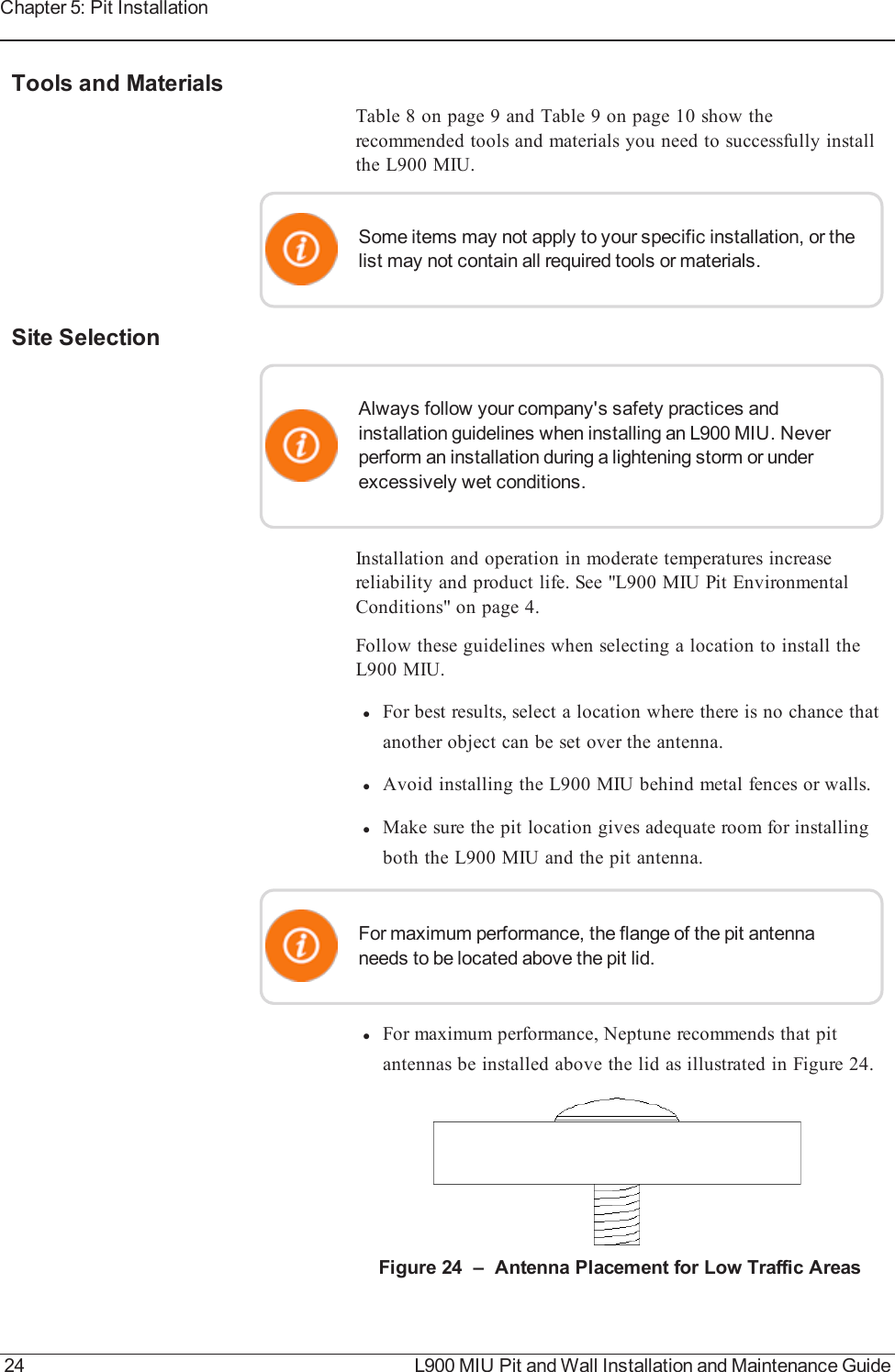
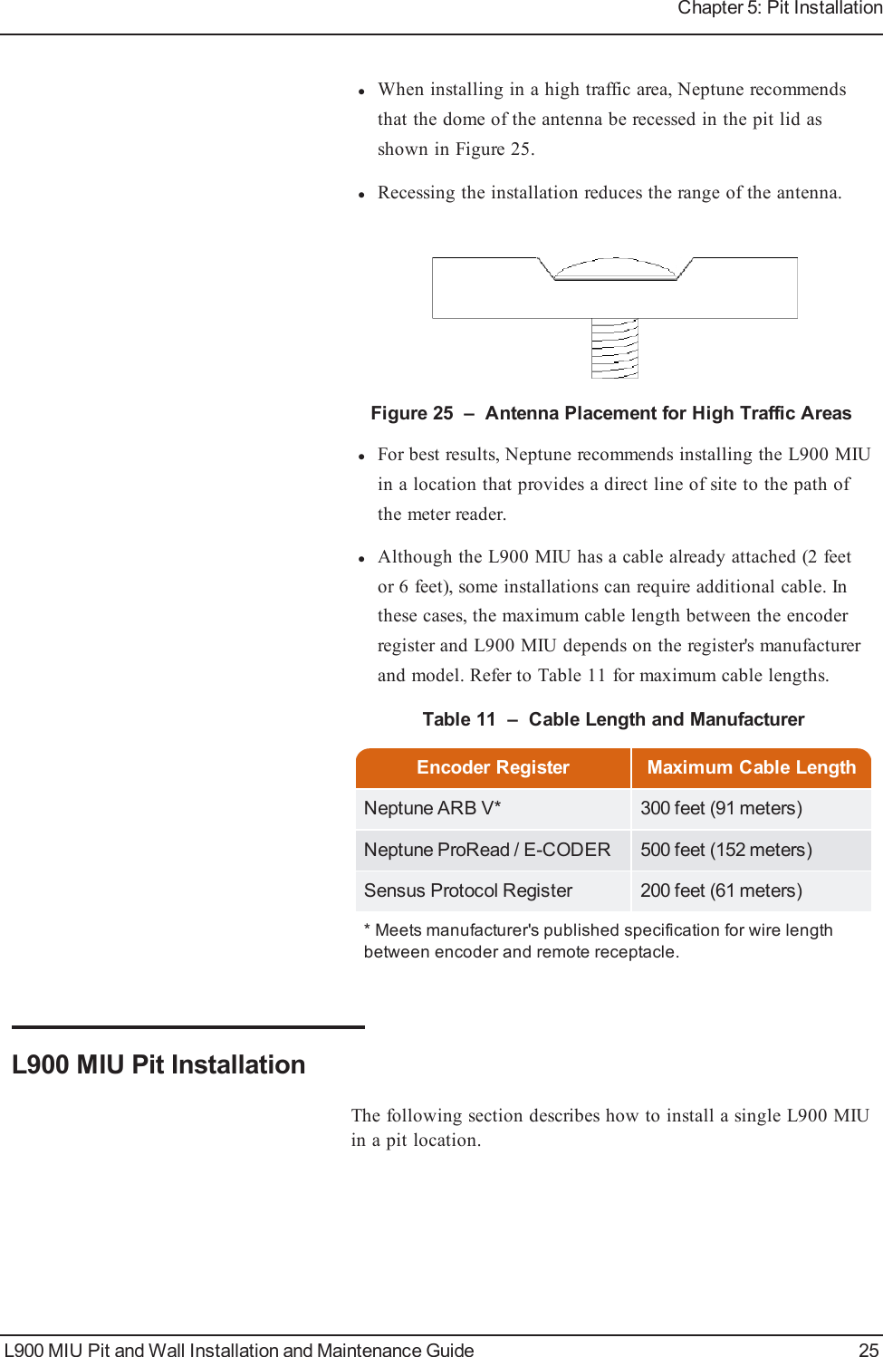
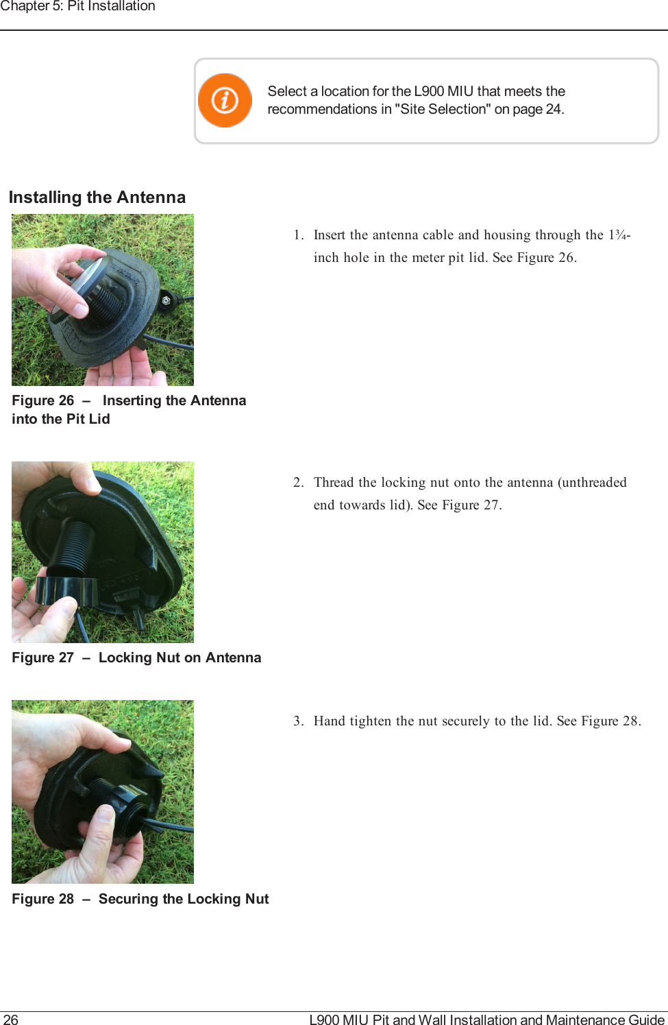
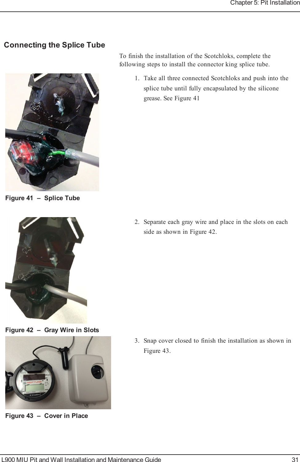
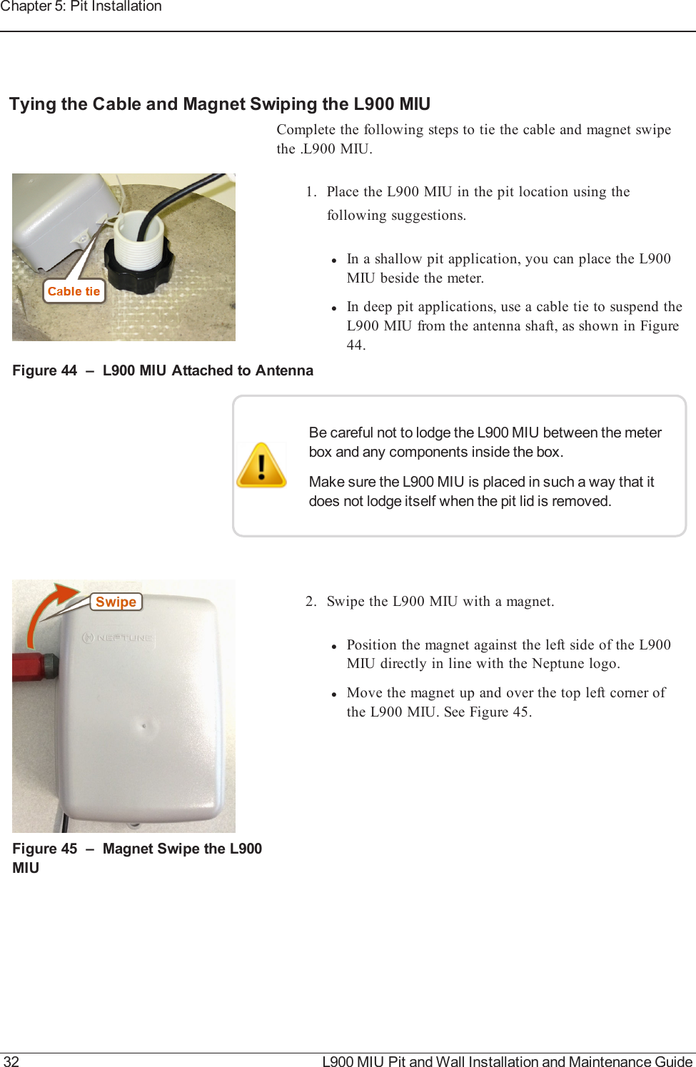
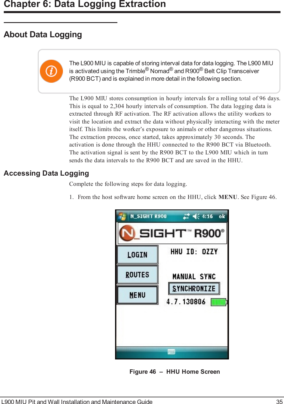
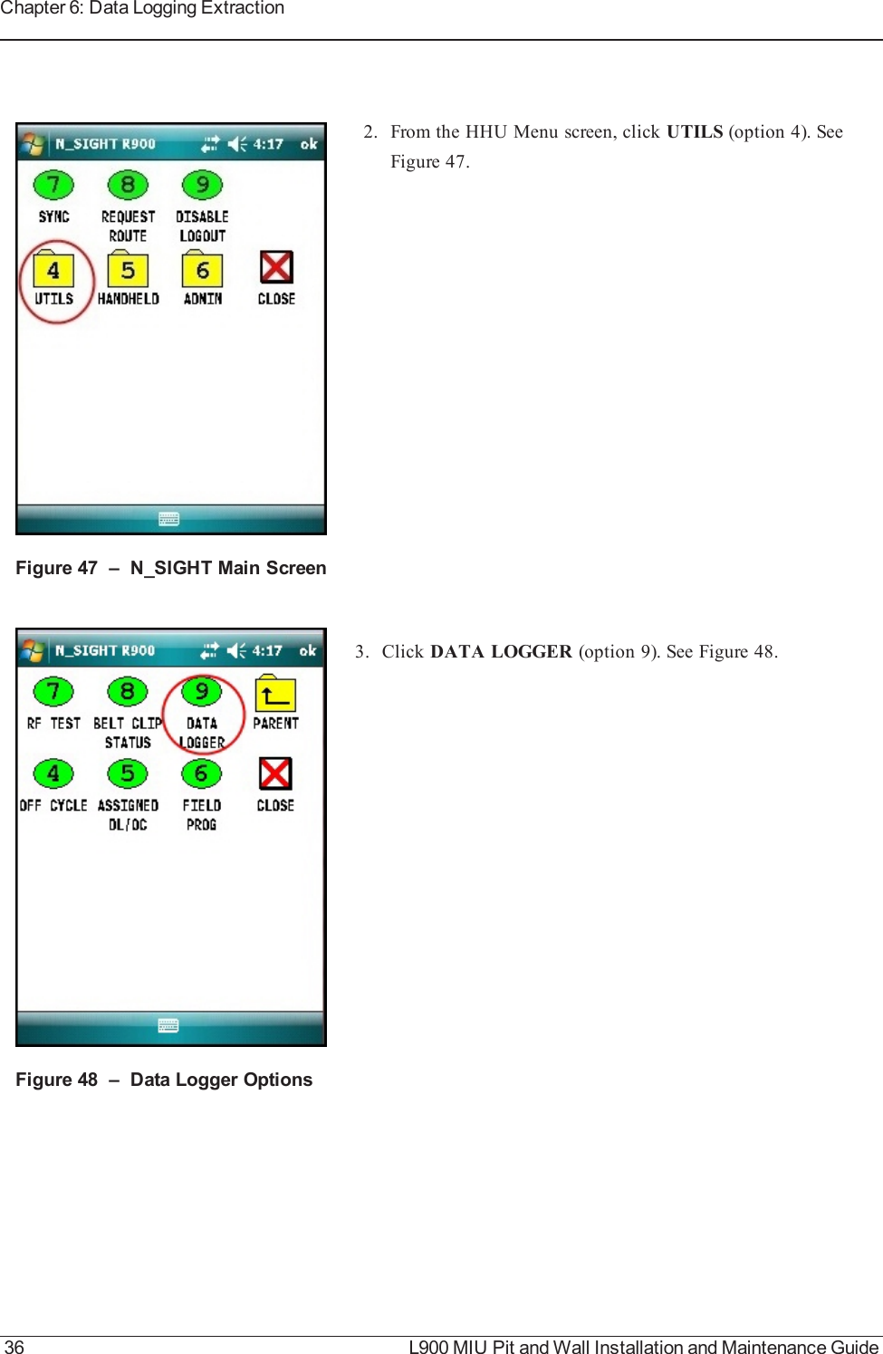
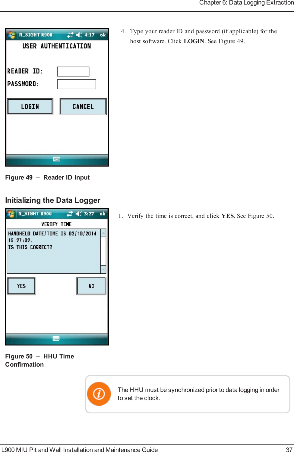
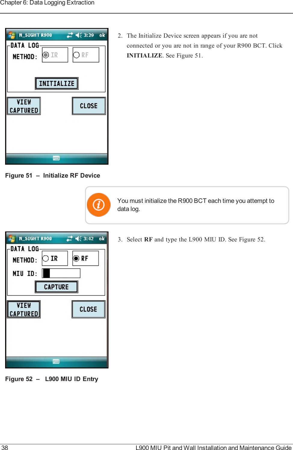
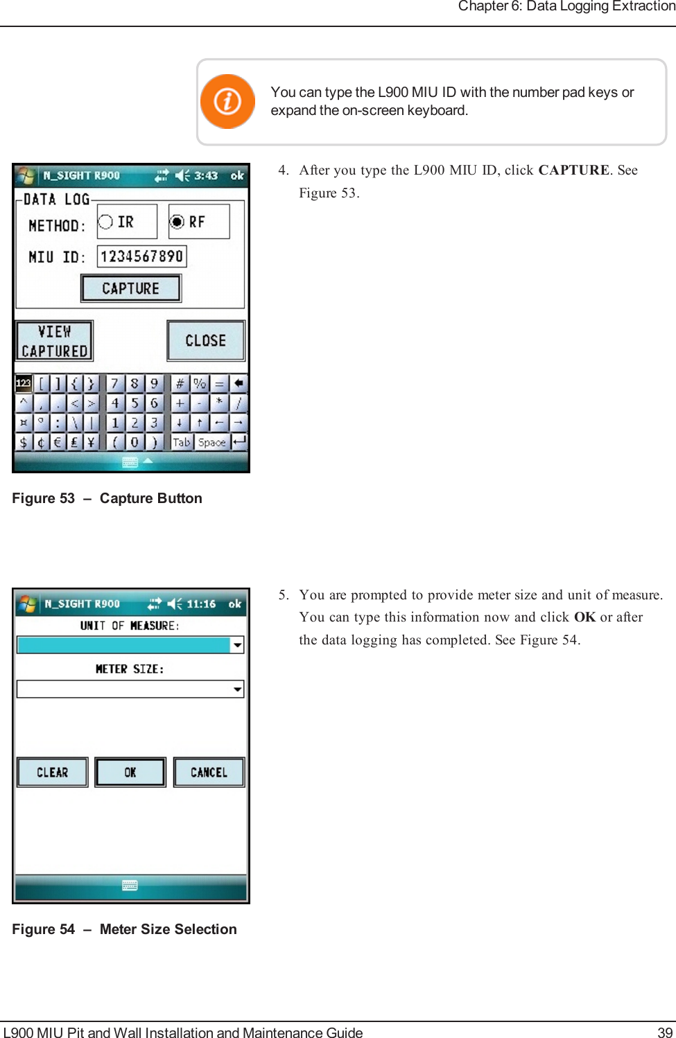
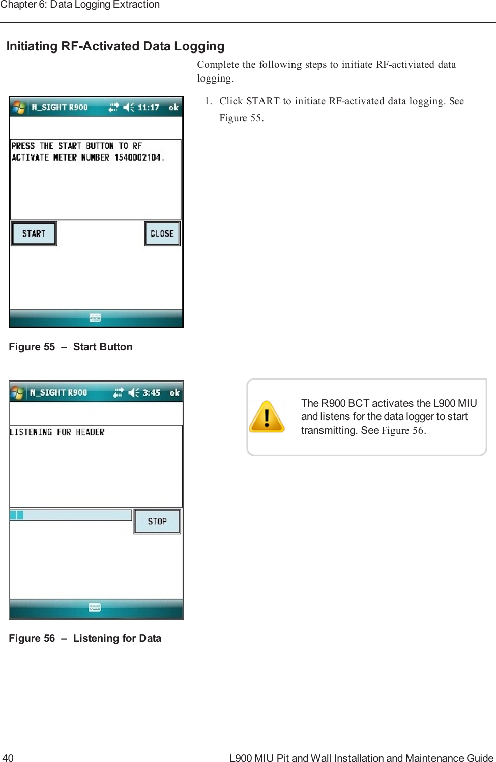
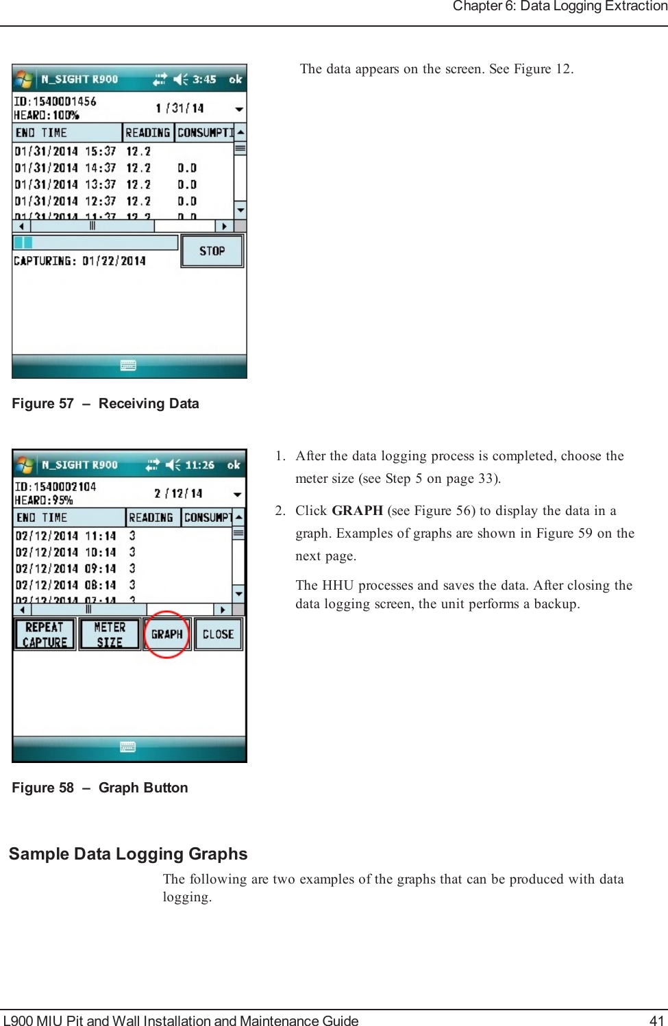
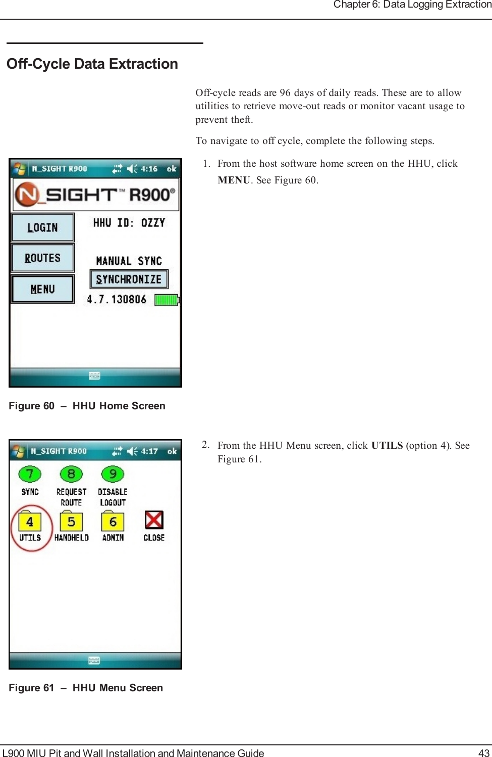
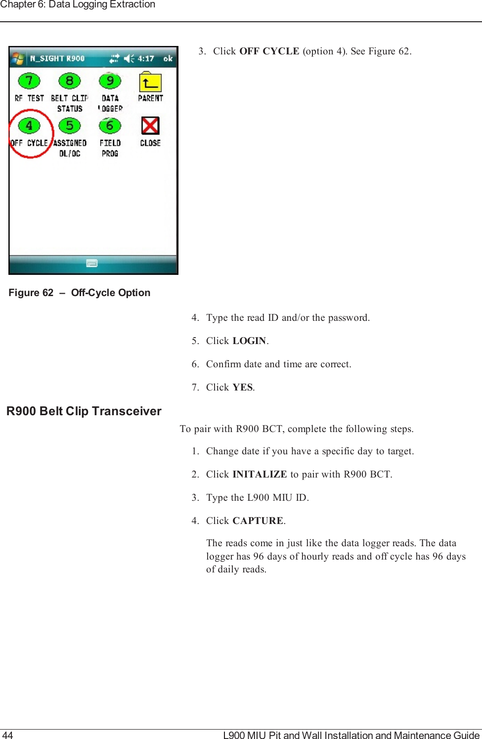
User Manual Part B