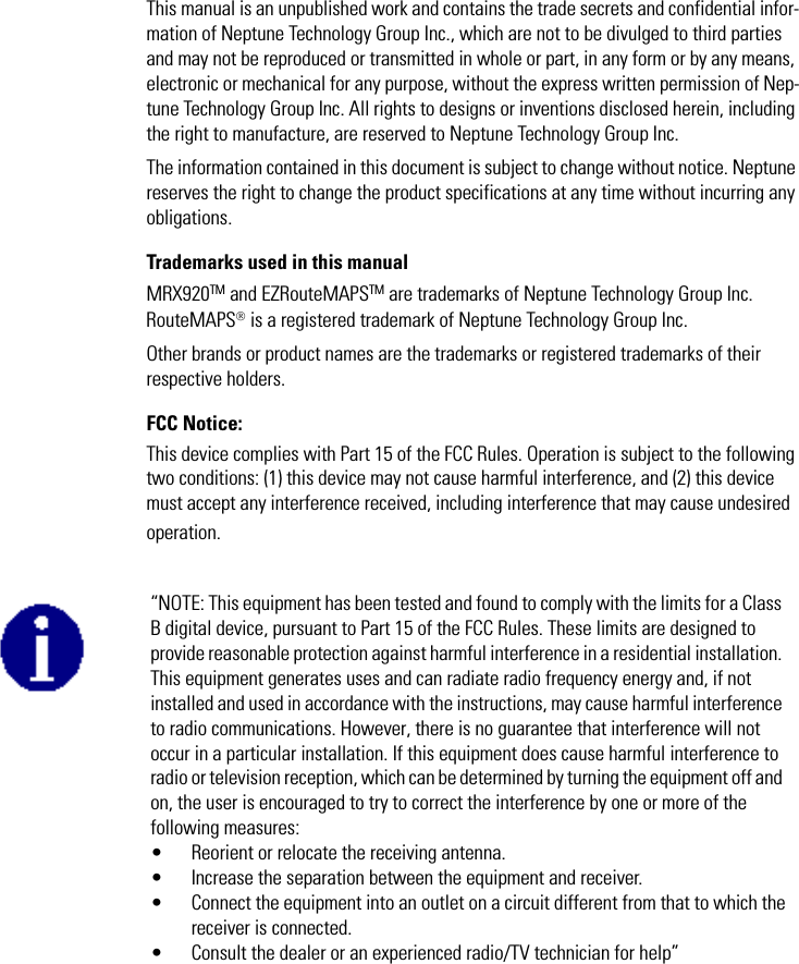
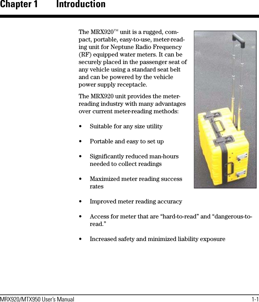
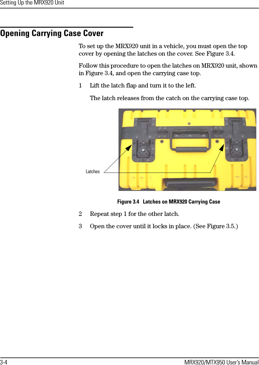
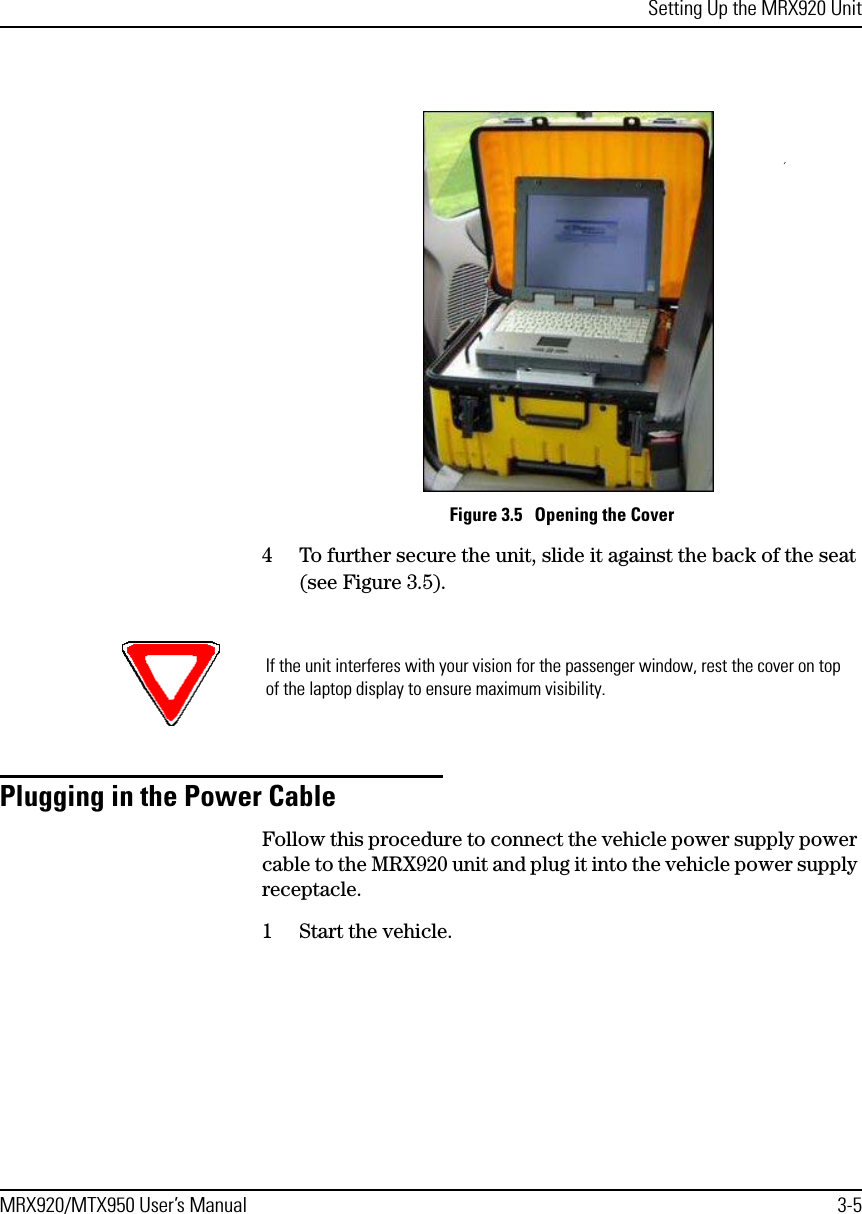
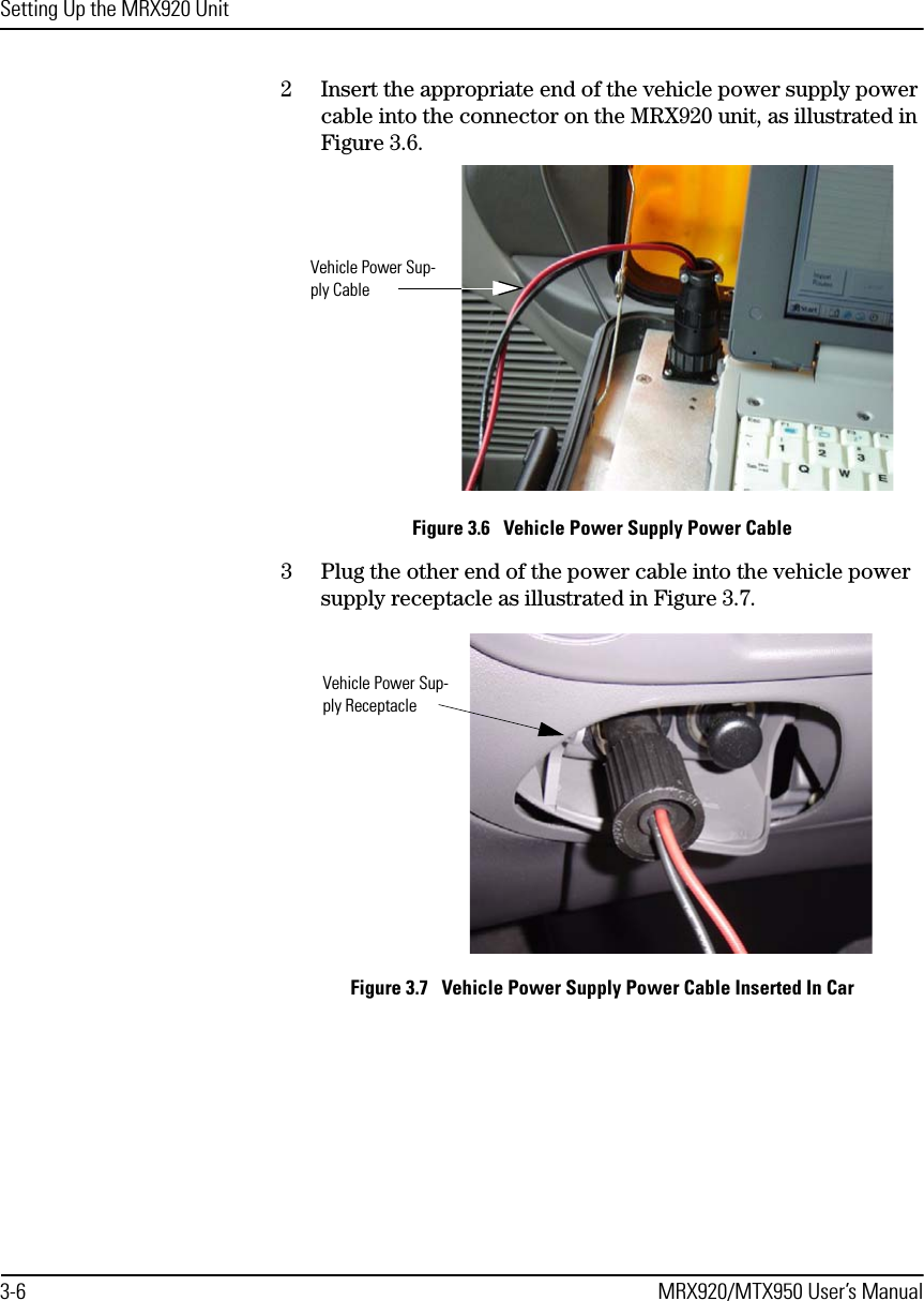
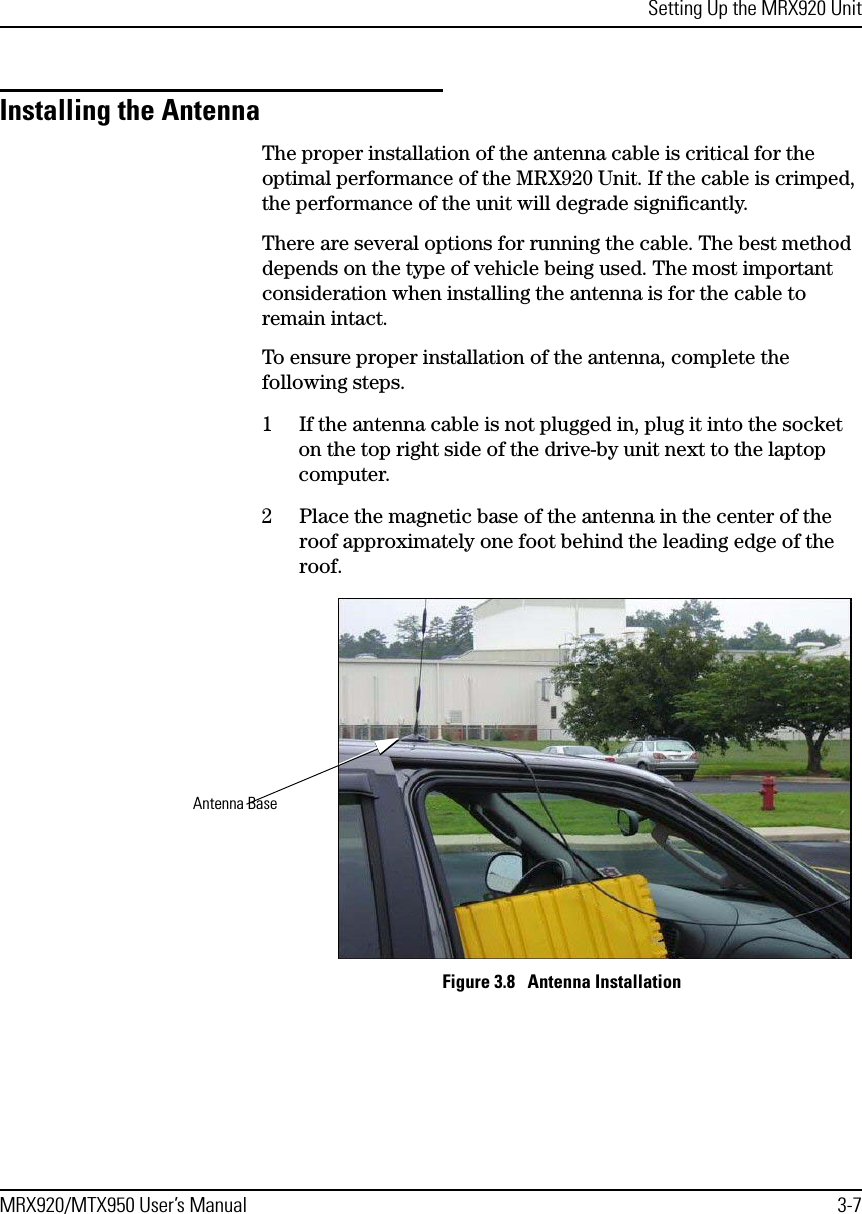
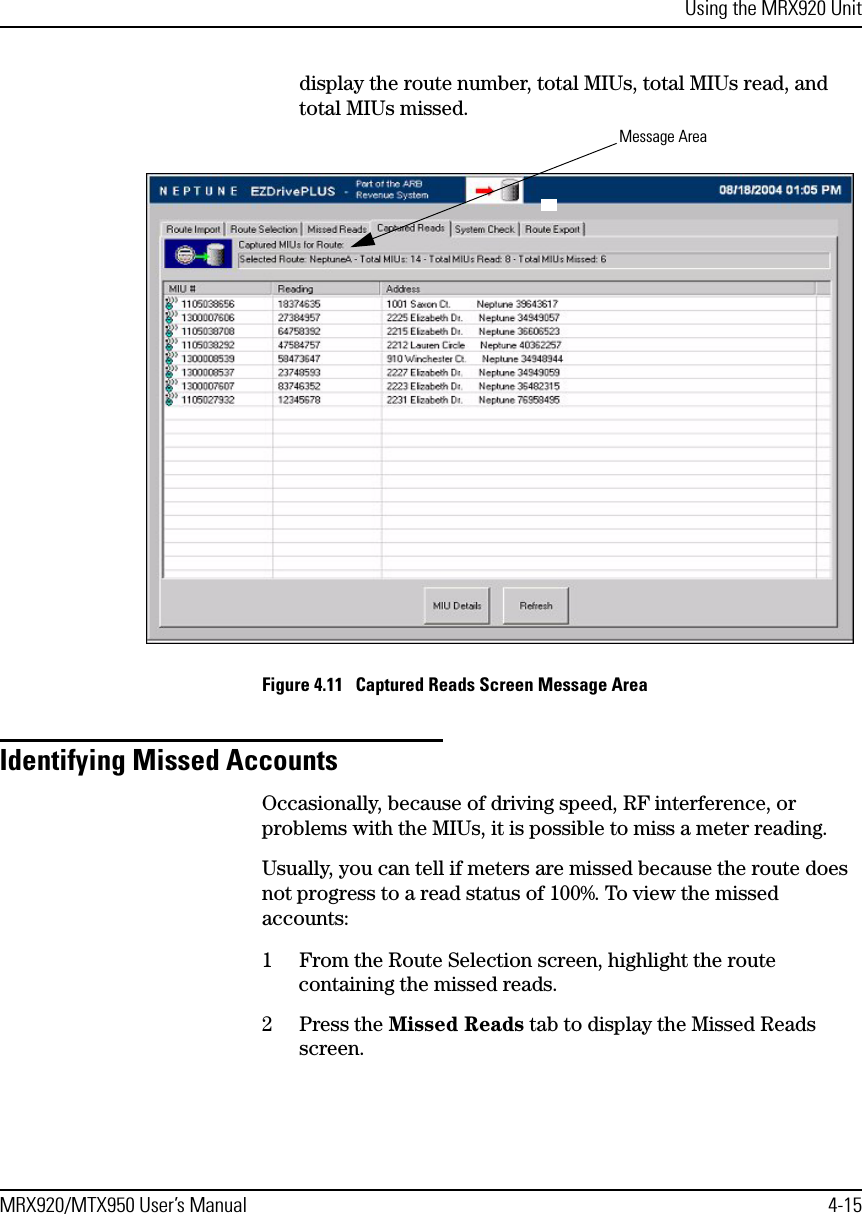
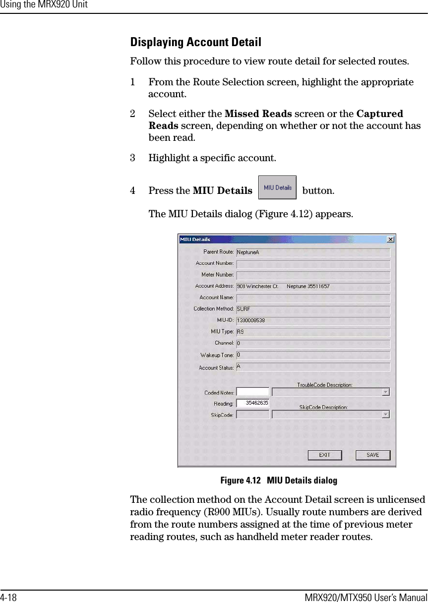
Neptune Technology Group MTX950 MOBILE DATA COLLECTOR User Manual USERS MANUAL
Neptune Technology Group Inc. MOBILE DATA COLLECTOR USERS MANUAL
UserManual.wiki
>
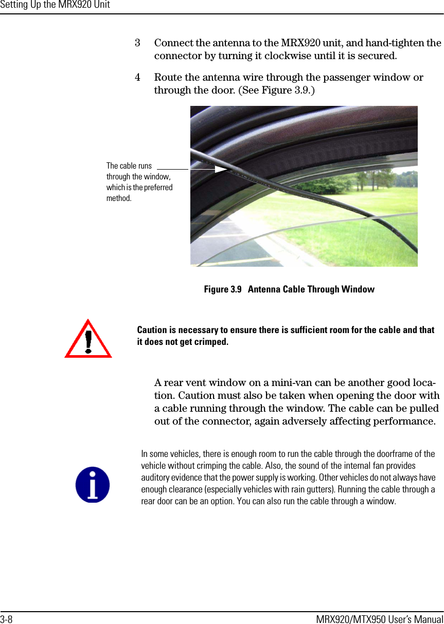
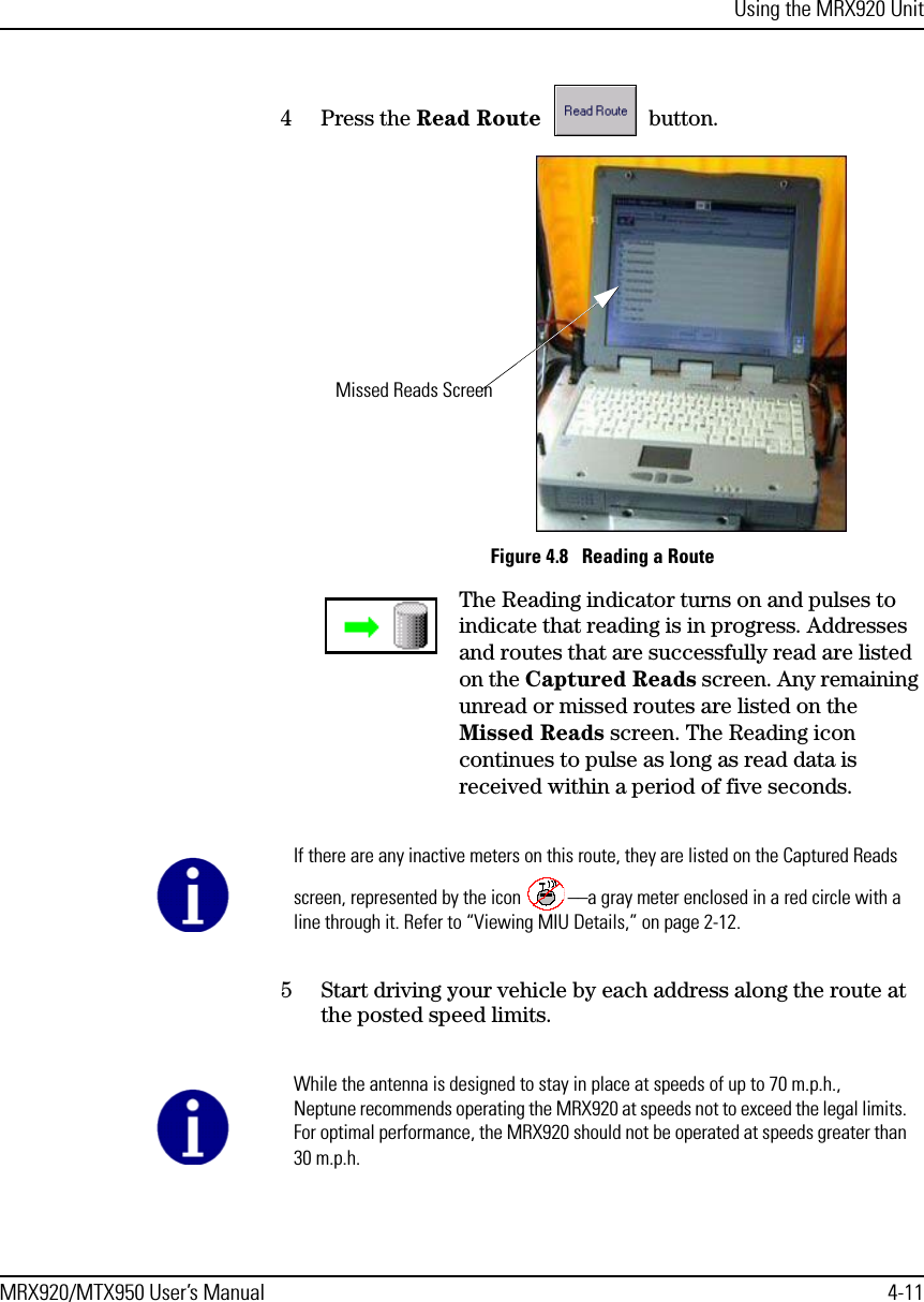
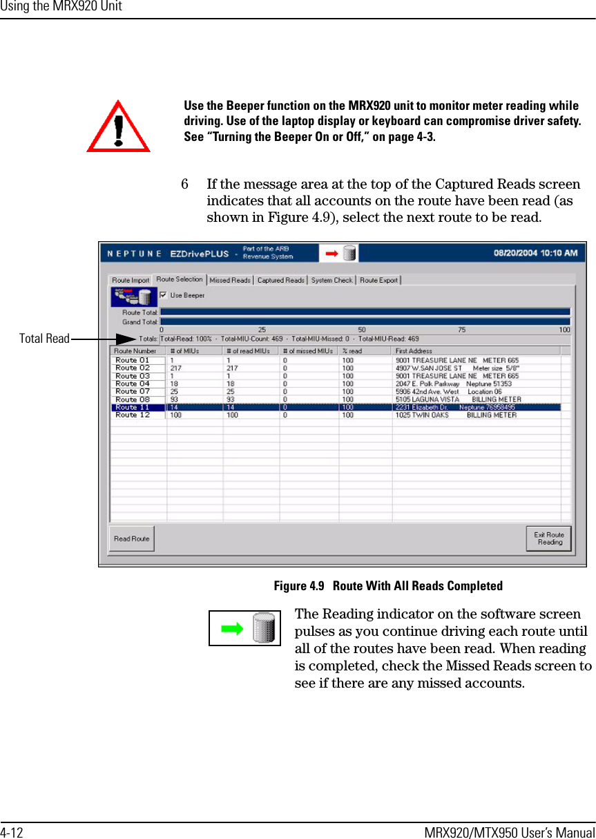
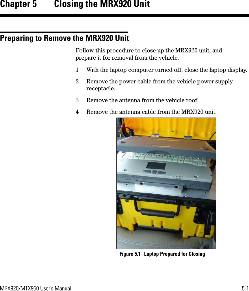
Neptune Technology Group
>
MTX950 User Manual
USERS MANUAL
Navigation menu
Upload a User Manual
Namespaces
Wiki Guide
HTML
PDF
Info
Views
User Manual
Discussion / Help
Navigation