Neptune Technology Group NTGR900G UTILIY METER DATA TRANSMITTER User Manual USERS MANUAL
Neptune Technology Group Inc. UTILIY METER DATA TRANSMITTER USERS MANUAL
USERS MANUAL

5015 B.U. Bowman Drive Buford, GA 30518 USA Voice: 770-831-8048 Fax: 770-831-8598
FCC Part 15.247
Transmitter Certification
Frequency Hopping Spread Spectrum Transmitter
Test Report
FCC ID: P2SNTGR900G
FCC Rule Part: 15.247
ACS Report Number: 06-0101-15C
Manufacturer: Neptune Technology Group, Inc.
Model: R900G
Installation and Operators Guide
~
ARBIJT.I L!TV MANAGEM ENT$YSTEM 5
~I~I~.I~~
~
~
w
U
Z
<
Z
w
.-
Z
<
~
Q
Z
<
Z
Q
.-
<
:::
<
.-
'"
z
~
=
=
0)
=
This manual is an unpublished work and contains the trade secrets and confidential information of Neptune Technology
Group Inc., which are not to be divulged to third parties and may not be reproduced or transmitted in whole or part, in
any form or by any means, electronic or mechanical for any purpose, without the express written permission of Nep-
tune Technology Group Inc. All rights to designs or inventions disclosed herein, including the right to manufacture, are
reserved to Neptune TechnoiogyGroup Inc.
Neptune engages in ongoing research and development to improve and enhance its products. Therefore, Neptune
reserves the right to change product or system specifications without notice.
Trademarks used in tbis manual
A900G is a trademark of Neptune Technology Group Inc. A900 is a trademark of Neptune Technology Group Inc Other
brands or product names are the trademarks or registered trademarks of their respective holders.
FCC Notice
This device complies with Part 15 of the FCC Rules. Operation is subject to the following two conditions: (1) this device
may not cause harmful interference. and (2) this device must accept any interference received. including interference
that may cause undesired operation.
NOTE: This equipment has been tested and found to comply with the limits for a Class B digital device, pursuant to
Part 15 of the FCC Rules. These limits are designed to provide reasonable protection against harmful interference in a
residential installation. This equipment generates. uses. and can radiate radio frequency energy and. if not installed
and used in accordance with the instructions, may cause harmful interference to radio communications. However, there
is no guarantee that interference will not occur in a particular installation If this equipment does cause harmful inter-
ference to radio or television reception. which can be determined by turning the equipment off and on. the user is
encouraged to try to correct the interference by one or more of the following measures
.ReoTienturrelocate1h~ receiving amenna.
.Increase the separation between the equipment and receiver.
.Connect the equipment into an outlet on a circuit different from that to which the receiver is connected
.Consult the dealer or an experienced radio/TV technician for help.
RF Exposure Information
This equipment complies with the FCC RF radiation requirements for uncontrolled environments. To maintain compli-
ance with these requirements. the antenna and any radiating elements should be installed to ensure that a minimum
separation distance of 2Ocm is maintained from the general population.
Professional Installation
In accordance with section 15.203 of the FCC rules and regulations, the MIU must be professionally installed by trained
utility meter installers. Changes or modifications not expressly approved by the party responsible for compliance could
void the user's authority to operate the equipment
(f)NE?TUNE
TECHNOLOGY GROUP
ARB UTILITY MANAGEMENT SYSTEMS WATER I ELECTRIC GAS
R900G TM Installation and Maintenance Guide

Industry Canada
This Class B digital apparatus meets all requirements of the Canadian Interference Causing Equipment Regulations.
Operation is subject to the following two conditions: (1) this device may not cause harmful interference, and (2) this
device must accept any interference received, including interference that may cause undesired operation.
Cet appareillage numerique de la classe B repond a toutes les exigences de /'interference canadienne causant des
reglements d'equipement. l'operation est sujette aux deux conditions suivantes: (1) ce dispositif peut ne pas causer
/'interference nocive, et (2) ce dispositif doit accepter n'importe quelle interference recue, y compris /'interference qui
peut causer /'operation peu desiree.
R!KKJG Installation and Maintenance Guide
literature No. 1M R900G 03.06
Part NoXXXXX-XXX
Neptune Technology Group Inc.
1600 Alabama Highway 229
Tallassee, Al36078
Tel: 1334) 283-6555
Fax: (334) 263-7299
Copyright @ 2006
Neptune Technology Group Inc
All Rights Reserved.
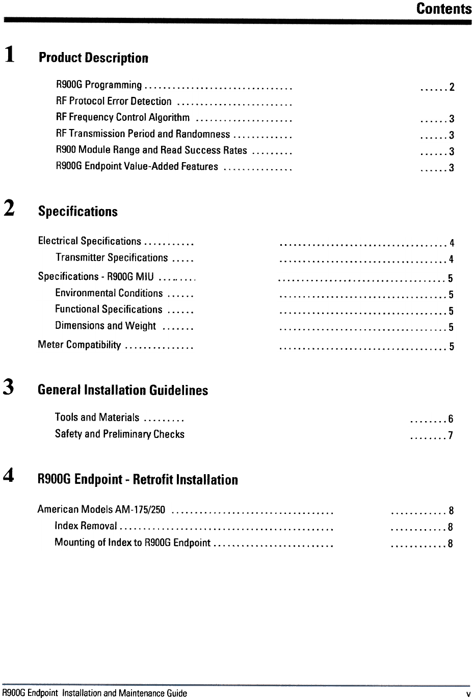
Contents
1
Product Description
R900G Programming RFProtocolErrorDetection RF Frequency Control Algorithm """."""""""
RF Transmission Period and Randomness. R900Moduie Range and Read Success Rates R900G Endpoint Value-Added Features
2
...3
...
3
..3
3
2Specifications
"'" 4
4
5
5
5
5
5
Electrical Specifications. Transmitter Specifications. Specifications -R900G MIU Environmental Conditions. Functional Specifications. Dimensions and Weight Meter Compatibility """"' "
3General Installation Guidelines
6
7
Tools and Materials. Safety and Preliminary Checks
4R900G Endpoint -Retrofit Installation
8
8
8
American ModelsAM-175/250 Index Removal. Mounting of Index to R900G Endpoint
R900G Endpoint Installation and Maintenance Guide v

Contents
R900G Endpoint Installation and Maintenance Guide
vi
Figures
Figure Title Page
R900GEndpoint R900G MIU Dimensions. 2
5
2
R900G Endpoint Installation and Maintenance Guide vii

Figures
Notes:
Tables
Table Title Page
Recommended Tools Recommended Materials. . .6
.6
2
.
R900G Endpoint Installation and Maintenance Guide IX

Figures
Notes:
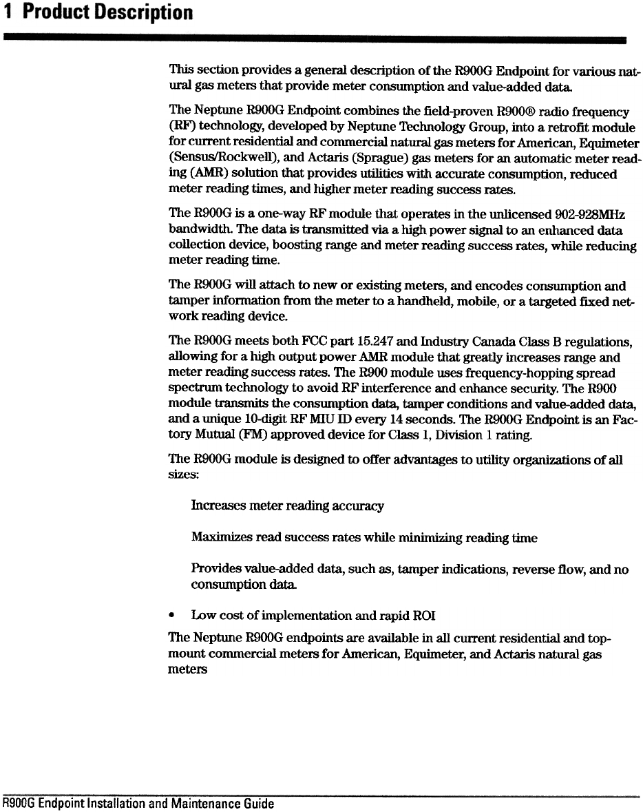
This section provides a general description of the ROOOG Endpoint for various nat-
ural gas meters that provide meter consmnption and value-added data.
The Neptune ROOOG Endpoint combines the field-proven R9OO@ radio frequency
(RF) technology, developed by Neptune Technology Group, into a retrofit module
for current residential and commercial natural gas meters for American, Equimeter
(SensusIRockwell), and Actaris (Sprague) gas meters for an automatic meter read-
ing (AMR) solution that provides utilities with accurate consumption, reduced
meter reading times, and higher meter reading success rates.
The ROOOG is a one-way RF module that operates in the unlicensed 002-928MHz
bandwidth. The data is transmitted via a high power signal to an enhanced data
collection device, boosting range and meter reading success rates, while reducing
meter reading time.
The R900G will attach to new or existing meters, and encodes consumption and
tamper information from the meter to a handheld, mobile, or a targeted fixed net-
work reading device.
The R900G meets both FCC part 15.247 and Industry Canada Class B regulations,
allowing for a high output power AMR module that greatly increases range and
meter reading success rates. The R900 module uses frequency-hopping spread
spectrum technology to avoid RF interference and enhance security. The ROOO
module transmits the consumption data, tamper conditions and value-added data,
and a unique 10-digit RF MIU ill every 14 seconds. The ROOOG Endpoint is an Fac-
tory Mutual (FM) approved device for Class 1, Division 1 rating.
The R900G module is designed to offer advantages to utility organizations of all
sizes:
Incre~es meter reading accuracy
Maximizes read success rates while minimizing readillg time
Provides value-added data, such as, tamper indications, reverse flow, and no
consumption data.
.Low cost of implementation and mpid ROI
The Neptune R900G endpoints are available in all cUlTent residential and top-
mount commercial meters for American, Equimeter, and Actaris natural gas
meters
R900G Endpoint Installation and Maintenance Guide
Product Description
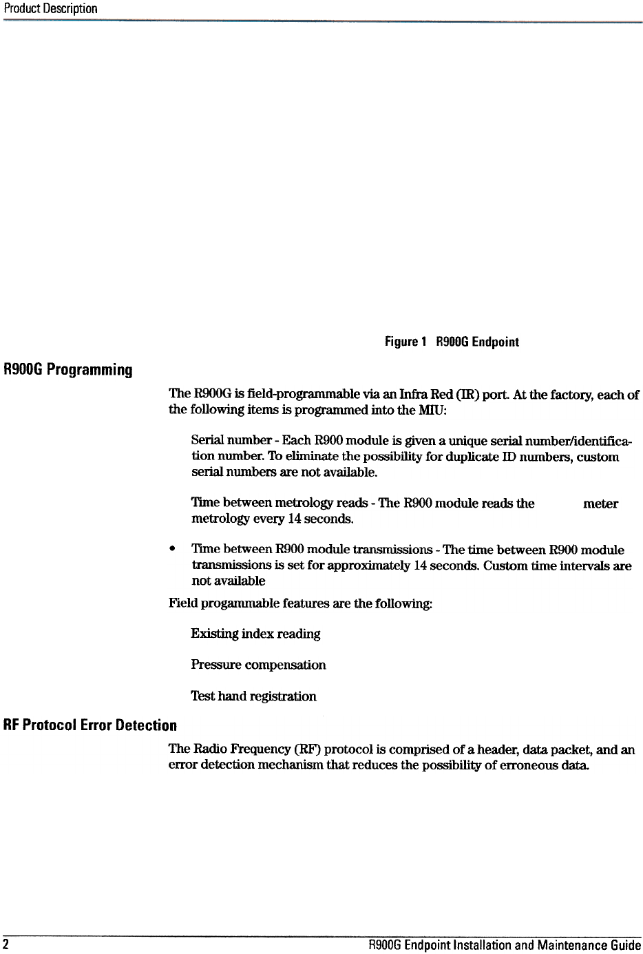
Figure 1 R900G Endpoint
R900G Programming
The R9OOG is field-programmable via an Infra Red (IR) port. At the factory, each of
the following items is progranuned into the Mill:
Serial number -Each R900 module is given a unique serial number/identifica-
tion number. To eliminate the possibility for duplicate ID numbem, custom
serial numbem are not available.
Time between metrology reads -The R900 module reads the
metrology every 14 seconds. meter
.Time between R900 module transmissions -The time between R900 module
transmissions is set for approximately 14 seconds. Custom time intervals are
not available
Field progammable features are the following:
Existing index reading
Pressure compensation
Test hand registration
RF Protocol Error Detection
The Radio Frequency (RF) protocol is comprised of a header, data packet, and an
error detection mechanism that reduces the possibility of erroneous data.
2R900G Endpoint Installation and Maintenance Guide
Product Description
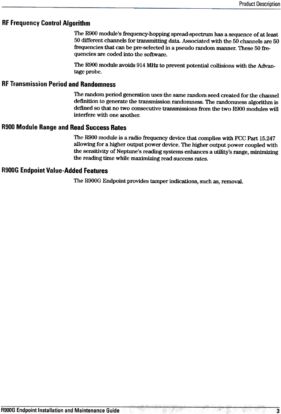
RF Frequency Control Algorithm
The ROOO module's frequency-hopping spread-spectrum has a sequence of at least
50 different channels for transmitting data. Associated with the 50 channels are 50
frequencies that can be pre-selected in a pseudo random manner. These 50 fre-
quencies are coded into the software.
The R900 module avoids 914 MHz to prevent potential collisions with the Advan-
tage probe.
RF Transmission Period and Randomness
The random period generation uses the same random seed created for the channel
definition to generate the transmission randomness. The randomness algoritlun is
defined so that no two consecutive transmissions from the two R900 modules will
interfere with one another.
R900 Module Range and Read Success Rates
The R900 module is a radio frequency device that complies with FCC Part 15.247
allowing for a higher output power device. The higher output power coupled with
the sensitivity of Neptune's reading systems enhances a utility's range, minimizing
the reading time while maximizing read success rates.
R900G Endpoint Value-Added Features
The R900G Endpoint provides tamper indications, such as, removal
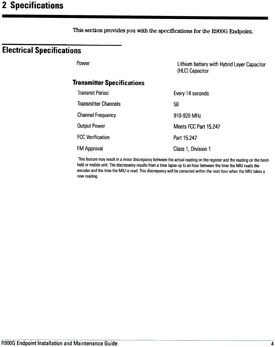
This section provides you with the specifications for the ROOOG Endpoint
Electrical Specifications
Power lithium battery with Hybrid layer Capacitor
(HlC) Capacitor
Transmitter Specifications
Transmit Period Every 14 seconds
Transmitter Channels
Channel Frequency
50
910-920 MHz
Meets FCC Part 15.247
Part 15.247
Output Power
FCC Verification
FM Approval Class 1, Division 1
'This feature may result in a minor discrepancy between the actual reading on the register and the reading on the hand-
held or mobile unit. The discrepancy results from a time lapse up to an hour between the time the MIU reads the
encoder and the time the MIU is read. This discrepancy will be corrected within the next hour when the MIU takes a
new reading
R900G Endpoint Installation and Maintenance Guide 4
Specifications
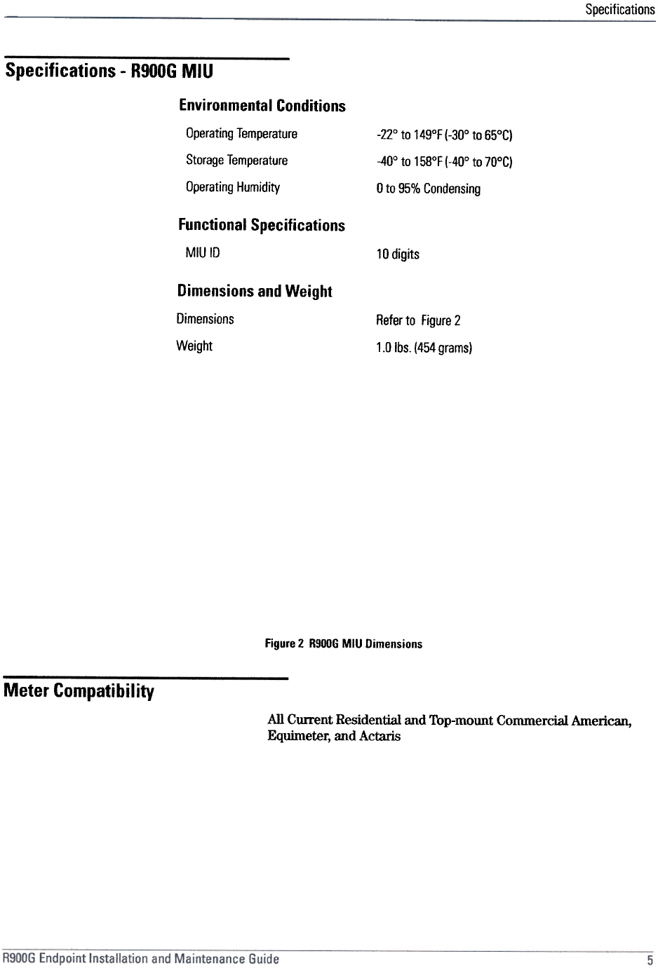
Specifications -R900G MIU
Environmental Conditions
-22° to 149°F (-30° to 65°C)
-40° to 158°F (-40° to 70°C)
0 to 95% Condensing
Operating Temperature
Storage Temperature
Operating Humidity
Functional Specifications
MIUID 10 digits
Dimensions and Weight
Dimensions
Weight
Refer to Figure 2
1.0 Ibs.(454 grams)
Figure 2 R900G MIU Dimensions
Meter Compatibility
All Current Residential and Top-mount Commercial American,
Equirneter, and Actaris
3 General Installation Guidelines
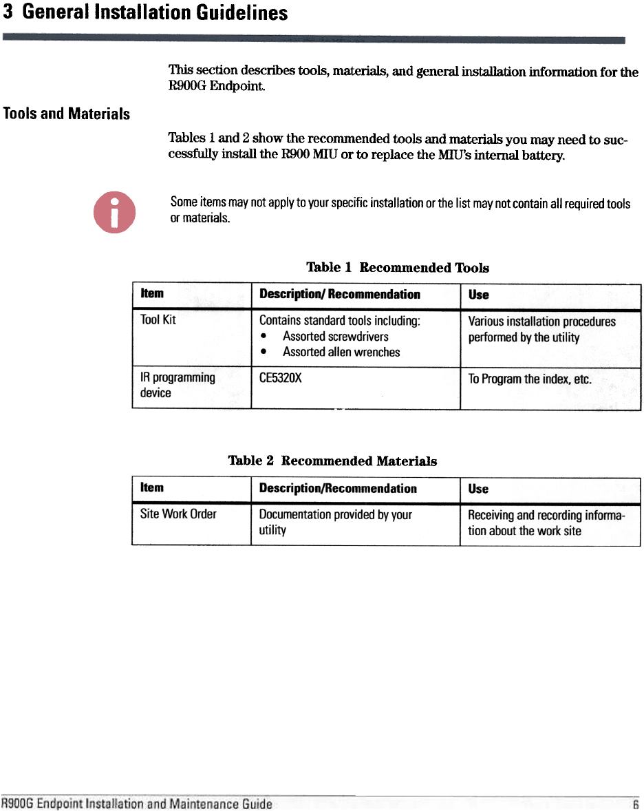
This section describes tools, materials, and general jnstallation information for the
ROOOG Endpoint.
Tools and Materials
Tables 1 and 2 show the recommended tools and materials you may need to suc-
cessfully install the ROOO MIU or to replace the MIU's internal battery.
Some items may not apply to your specific installation or the list may not contain all required tools
or materials.
Table 1 Recommended Tools
Table 2 Recommended Materials
Item Descripti on/Recommendati on Use
Site Work Order Documentation provided by your
utility
Receiving and recording informa-
tion about the work site
General Installation Guidelines
Safety and Preliminary Checks
ObselVe the following safety and preliminary checks before and during each instal-
lation:
Verify that you are at the location specified on the Site Work Order.
Verify that the site is safe for you and your equipment.
Notify the customer of your presence and tell the customer that you will need
access to the water meter.
If the Site Work Order does not have an Mill ill number on it, write in the ill
number(s) of the Mill you are about to install. If the Site Work Order already
has an Mill ill number on it, verify that it matches the ill numbers on the Mill
you are about to install.
American Models AM-175/250
Index Removal
Complete the following steps for index removal.
1Use a flathead screwdriver to puncture and remove the tamper plugs, if
present.
2Use a large screwdriver to remove and discard the four lens mounting screws
and the lens.
3Remove the gasket.
4Use a small screwdriver to remove the index mounting screws and the index.
Mounting of Index to R900G Endpoint
Complete the following steps to mount the index to a ROOOG Endpoint.
Carefully mate the drive dog from the index to the drive dog of the ROOOG
Endpoint.
2Secure the index to the module using the two index screw from Step 4 in the
previous section.
3Place clear plastic covers over the front of the w1it.
4Use the four mounting screws that are supplied to attach the entire assembly
to the gas meter main case.
5Program tile installation.
6Test tile installation
7Place new tamper plugs over the screws.
R900G Endpoint Installation and Maintenance Guide 8
Index
G
general description 1
A
algorithm
randomness 3
RF frequency control 3
antenna. RF 1 H
handheld. reading 4
HLC capacitor 4
Hybrid Layer Capacitor 4
B
battery
internal 6
lithium 4
index, removal 8
indications, tamper 3
Industry Canada notice iii
installation
importance of professional ii
preliminary checks 7
safety 7
interference canadienne iii
IR programming device 6
C
Canadian Interference Causing Equipment Regulations iii
capacitor, HlC 4
channel
for transmitting data 3
frequency 4
transmitter 4
compatibility, meter 5
conditions, environmental 5 L
LCD. definition 1
Liquid Crystal Display 1
M
materials, recommended 6
meter compatibility 5
metrology reads 2
MIUID 1
MIU, definition 1
D
data collection device 1
device
approved 1
data collection 1
higher output power 3
IR programming 6
output power 3
RF 3
targeted fixed network 1
dimensions 5 N
E
electrical specifications 4
environmental conditions 5
notices
FCC ii
Industry Canada iii
0
F
FCC operating humidity 5
operating temperature 5
output power 3
p
period, transmit 4
power, output 3, 4
preliminary checks 7
notice ii
verification 4
features. value-added 3
FM approval 4
frequency-hopping 3
functional specifications 5
R900G Endpoint Installation and Maintenance Guide 1-1
Index
specifications
dimensions 5
electrical 4
encoder register interface 5
environmental conditions 5
functional 5
MIUID 5
transmitter 4
weight 5
spread-spectrum 3
storage temperature 5
T
R
R900@ radio frequency (RF) 1
R900G
description 1
dimensions 5
general description 1
interface 5
module reads 2
module transmissions 2
serial number 2
specifications 4
tools and materials 6
weight 5
radio technology 1
random period generation 3
reads, success rates 3
regulations, Canadian iii
RF antenna. 1
exposure information ii
frequency 3
module 1
protocol, error detection 2
technology 1
transmission 3
tamper
nail 1
plugs 8
temperature, storage 5
time intervals, custom 2
tools, recommended 6
transmission
randomness 3
RF 3
Transmitter specifications 4
v
verification. FCC 4
s
safety checks 7
serial number 2
site work order 6
w
weight. R900G 5
antenna 1
work order. site 6
1-2 R900G Endpoint Installation and Maintenance Guide