Neptune Technology Group NTR900GDL R900GDL User Manual FCC Part 15
Neptune Technology Group Inc. R900GDL FCC Part 15
UserManual.wiki
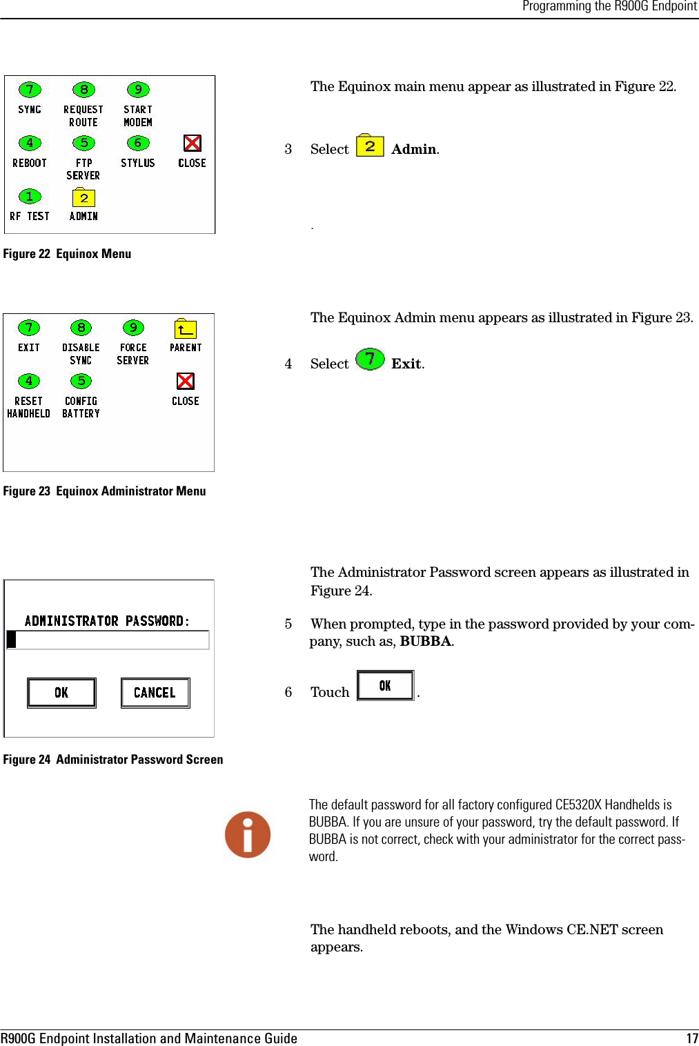
>
Neptune Technology Group
>
NTR900GDL User Manual
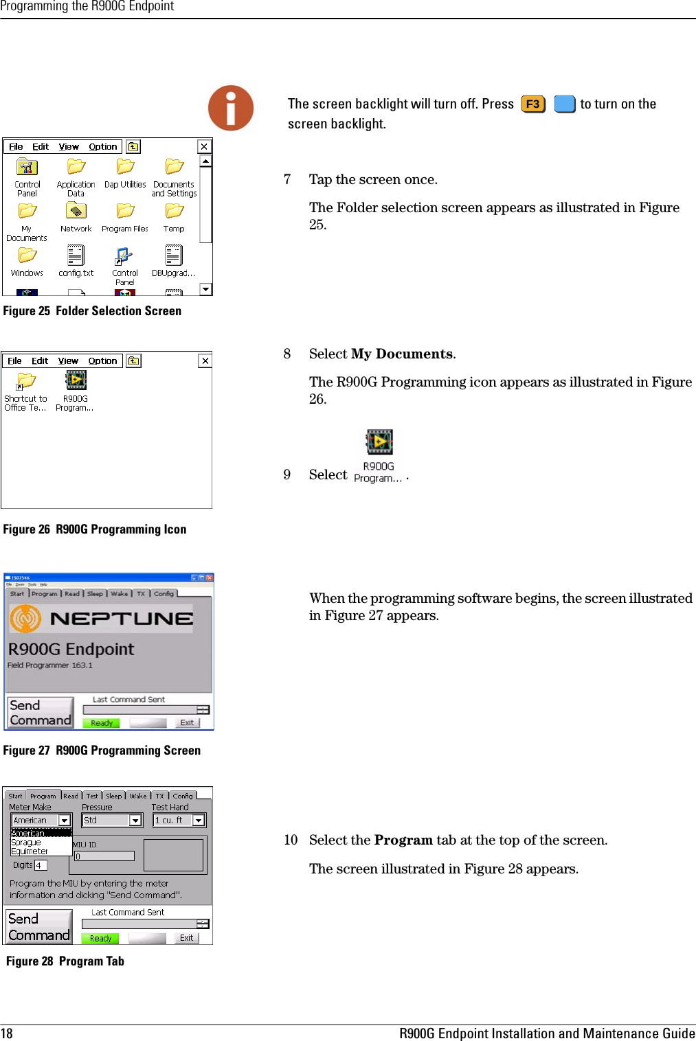
Manual
Navigation menu
Upload a User Manual
Namespaces
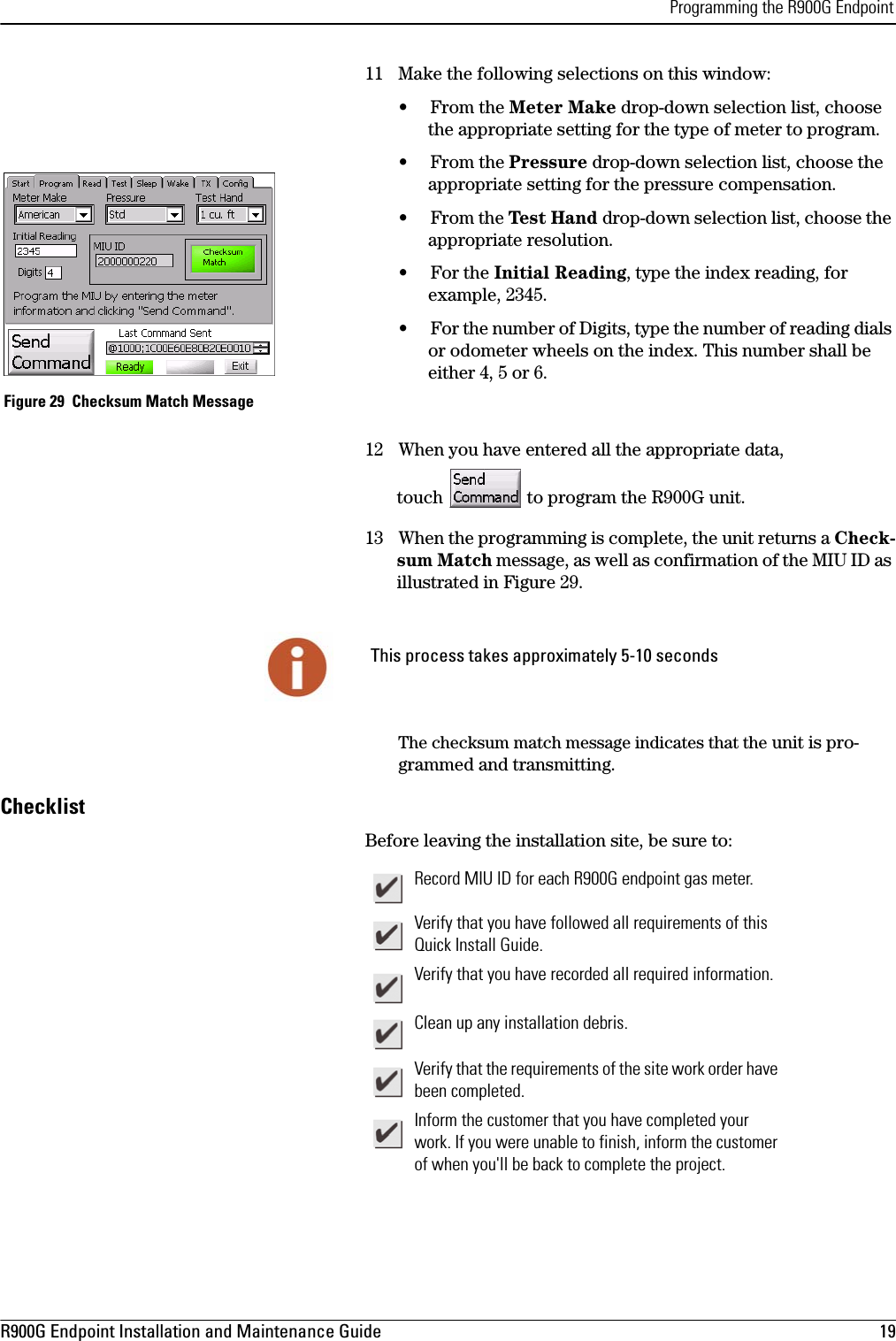
Wiki Guide
HTML
PDF
Info
Views
User Manual
Discussion / Help
Navigation