Neptune Technology Group R450DC DATA COLLECTOR User Manual IM R450 Rack Mount DC
Neptune Technology Group Inc. DATA COLLECTOR IM R450 Rack Mount DC
Contents
- 1. 450-Rack Mount DC Manual 2
- 2. User Manaul Rack Mount DC
450-Rack Mount DC Manual 2
Connecting the UPS
This section provides information on what tools, materials and
procedures are needed to connect the UPS.
Tools and Materials Required
The following list describes the tools and materials needed to connect
the UPS.
lSlotted-tip screwdrivers for tightening screws on terminal blocks.
lAC/DC voltmeter.
Procedures
Complete the following steps.
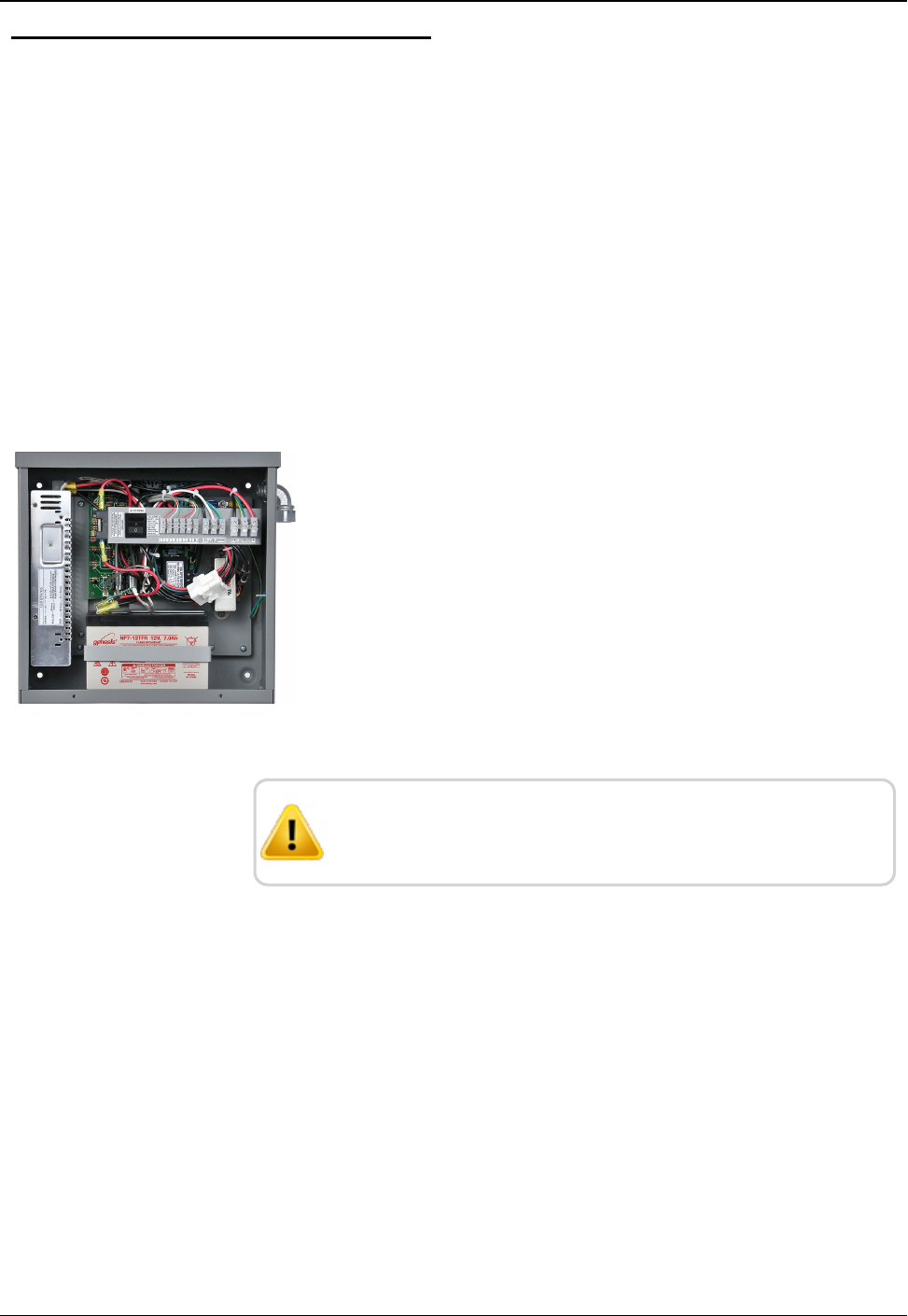
Step 1:Wiring the Input and Output Connectors
1. Remove the two screws that secure the UPS cover.
2. Remove the UPS cover.
Figure 34 – Wire Input and Output Connectors
The UPS contains a vent on the upper right side of the case;
do not remove this.
Step 2: Installing and Wiring the Batteries
1. Install Liquid-Tight Flexible Non-Metallic Conduit from the
disconnect switch to the lower 1/2' conduit hole on the side of the
UPS.
2. Install the black, white, and green wires through the conduit and
terminate to the terminal block inside the UPS.
40 R450 Rack Mount DC Installation and Maintenance Guide
Chapter 4: Uninterruptible Power Supply
Powering ONthe UPS
1. Install the DC cord grip in the upper 1/2" conduit hole on the side
of the UPS; just above the conduit.
2. Route the open pigtail end of the DC power cable through the
cord grip and terminate to the DC terminal block inside the UPS.
3. Tighten the DC cord grip using pliers or a wrench.
4. Attach the power cord to the bottom of the R450 RM DC.
5. Turn the UPS power switch on.
6. Re-install the UPS cover and secure it with the two screws.
Servicing the UPS
This section provides information on servicing the UPS.
CAUTION: Before attempting to service the UPS, verify that
the disconnect device is turned OFF. Also verify that the
UPS switch is turned OFF.
Checking UPS Status LEDs
This section provides information on checking and troubleshooting
the UPS.
Complete the following steps to check the UPS status if the
R450 RM DC will not power up.
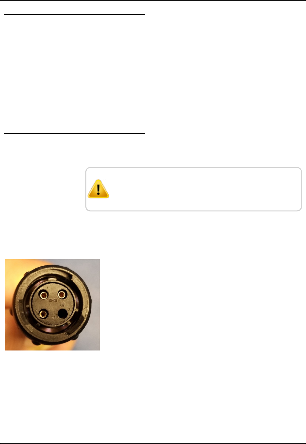
1. Remove the power plug from the bottom of the R450 RM DC.
2. Measure between pin-1 (+) and pin-2 (-) on the plug.
The voltage should measure 13.5-14.4 VDC. See Figure 35.
.
Figure 35 – R450 RM DC Power Plug
If the voltage measures okay, then there is a problem with the
R450 RM DC. Refer to "Potential R450 RM DCProblems" on
page46.
R450 Rack Mount DC Installation and Maintenance Guide 41
Chapter 4: Uninterruptible Power Supply
If the voltage is negative, there is a problem with the UPS wiring.
Complete the following steps.
1. Remove the UPS cover .
2. Correct the wiring issue.
3. Recheck wiring.
If there is no voltage present or the voltage is low (< 10.5V DC),
complete the following steps.
1. Remove the two screws that secure the UPS cover.
2. Remove the cover.
3. Verify the internal power switch is on.
4. Check the status LEDs inside the UPS. See Table 8 below.
LED
Indicators
Description
Green Solid on = AC okay
Off = AC failure
Yellow Solid on = battery fully charged
Blinking slowly = battery charging
Blinking rapidly = battery is discharging (possible AC input voltage
failure)
Red DCoutput is faulty (fuse may be blown)
Table 8 – UPS Status LEDs
5. Verify the UPS is producing the correct voltage at the output
terminals by measuring across DC+ (red) and DC- (black).
The voltage should measure 13.5-14.4 VDC.
This assumes the AC input voltage is present and the UPS internal
switch is on (i.e., battery should be charging).
If the AC input is not present, then the voltage across DC+ (red) and
DC- (black) should measure 10.5-12.8 VDC.
42 R450 Rack Mount DC Installation and Maintenance Guide
Chapter 4: Uninterruptible Power Supply

If the voltage is less than 10.5 VDC, this indicates a fully discharged
battery and must be recharged. Complete the following steps.
1. Measure the AC input voltage across L1 and N1.
The voltage should measure 100-140 VAC.
2. Verify the UPS's internal switch is On.
3. Check the UPS status LEDs. See Table 8.
Checkup Complete
After the UPS diagnostics has been completed, perform the following
steps.
1. Re-install the UPS cover.
2. Secure cover with two screws.
R450 Rack Mount DC Installation and Maintenance Guide 43
Chapter 4: Uninterruptible Power Supply

This page intentionally left blank.
Chapter 4: Uninterruptible Power Supply
44 R450 Rack Mount DC Installation and Maintenance Guide
R450 Rack Mount DC Installation and Maintenance Guide 45
Chapter 5: Troubleshooting
This section provides information for possible symptoms, areas of focus, and actions
that can be taken to resolve problems that could arise with your R450 Rack Mount
Data Collector (R450 RM DC).
Equipment Required
The following items are required in order to troubleshoot the R450 RM DC.
lKeys to access the site and open the R450 RM DC cabinet.
lDigital volt - Ohm multimeter
lVoltage Standing Wave Ration (VSWR) meter
lSocket and open-end wrenches to install/remove the R450 RM DC
lSmall, medium, and large slot style screw drivers
l#1 and #2 Phillips Head screw drivers
lElectrical tape and wire ties
lBackup R450 RM DC, if one fails
lR450 RM DC configuration USB flash drive
The USB flash drive must be configured for the specific R450 RM DC.
lAnti-static wrist strap and ground lead with alligator clip for attaching wrist strap to
the R450 RM DC cabinet
lMIU configured for site
lMagnet to swipe MIU
lR450 System Field Service Tool
PC Notebook Configuration
In order to use a notebook computer, consider the following.
lThe CalAmp modem requires an Ethernet cable to connect to the
network port of the computer.
lThe CalAmp modem uses an online application for configuration. It
does not require software to be installed to configure the modem.
Refer to the cellular modem's Quick Start Guide for log on and
setup instructions.
WARNING: Neptune does not recommend servicing an
R450 RM DC during inclement weather.
Potential R450 RM DCProblems
The following sections describe problems that can arise and how to
handle these potential problems.
Multiple R450 DCs Not Syncing with Host Database
Consider the following.
lHost database server is down or not connected to the Internet.
lRemote Internet, phone, cable, or cell service provider is either
down or experiencing degraded service.
lMultiple power outages affecting several sites.
Storm Damage Affecting Multiple Sites
One R450 RM DC is not syncing with the host database.
Troubleshooting this problem requires going to the R450 RM DC
site.
First Steps
Before leaving for the site, assess the health of the R450 RM DC
using the host system.
For instructions on how to assess the health of the R450 RM DC,
refer to "Using System Health" in the "System Health" chapter of
the N_SIGHT® R450 Online Help.
46 R450 Rack Mount DC Installation and Maintenance Guide
Chapter 5: Troubleshooting
lIf the R450 RM DC is offline, this indicates that they power, power
supply, CPU, or backhaul modem may not be functioning.
lSome sites are configured so that an operator can log on the
R450 RM DC remotely and look at the logs and watch the system
activity. If the R450 RM DC is offline but it is still possible to log
on the system, this indicates that the computer and backhaul
modem are both functional.
Initial Site Activities
lOpen the R450 RM DC and inspect the equipment.
lMake sure that there is no obvious physical damage to the system,
such as evidence of burned components or wires, which may
indicate a lightning strike. If there is any evidence of physical
damage, the R450 RM DC should be replaced with the spare and
returned to Neptune's repair facility.
CAUTION: The ground wrist strap must be clipped to the
box. Do not touch the computer circuit board or any of the
components if you are not wearing the wrist strap. Failure to
use the strap could cause damage to the computer due to
static electricity.
Checking the General Health of Each of the Modules
Visual Check of CPU Board Power
There are three Ethernet Status Light Emitting Diodes (LEDs) to the
left of the Ethernet RJ45 connector. The red LED closest to the
connector should be lit if there is power being supplied to the CPU
board. See Figure 36.
Figure 36 – Ethernet Status LED
R450 Rack Mount DC Installation and Maintenance Guide 47
Chapter 5: Troubleshooting
Visual Check of Radio Power
The radio has several indicator LEDs on the front panel. The green
Power indicator should be on. See Figure 37. If the amber ALM LED
is on, the radio is malfunctioning.
Figure 37 – Radio LEDs on Front Panel
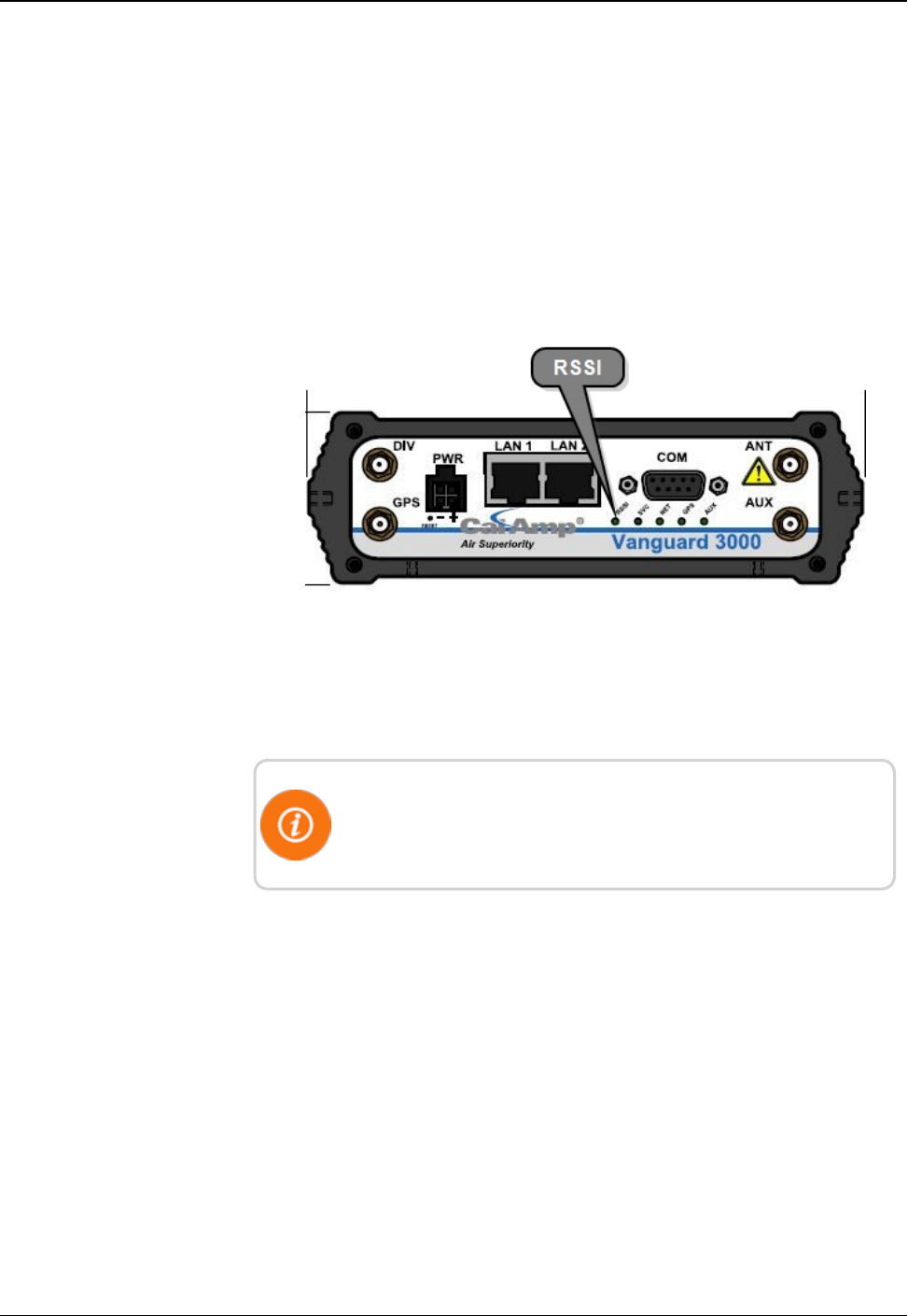
Visual Check of Backhaul Modem Power and Connectivity
Cal Amp Vanguard Modem
Look at the indicator lights on the modem to verify if the modem is
working. See Figure 38.
lIf the RSSI and SVC lights are on, this indicates that the modem is
connected.
lIf the RSSI and SVC lights are not on, this indicates that there is a
power problem with the modem. Verify that the main power is on.
lIf the SVC light is solid, the modem is connected to the cellular
network. See Table 9 on the facing page.
lIf the SVC light is flashing, the modem is trying to connect to the
network. See Table 9 on the facing page.
Figure 38 – Modem Indicator Lights
48 R450 Rack Mount DC Installation and Maintenance Guide
Chapter 5: Troubleshooting
The LEDs behavior is different than the table below at boot. The
sequence is: all read, all amber, all green, and all flash green
Function Off Green Flash Green Red Flash
Red
Amber Flash
Amber
RSSI Strong Weak/None Medium
SVC (cellular
network
connection)
36/4G 3G/4G/NC NC 2G 2G/NC
NET No
connectivity
Rx data Tx data Rx/Tx
GPS Disabled Fix Search no fix
AUX Disabled Good Failed
Table 9 – Modem Status LEDs
Additional Detail Checks
If any of the previous checks failed, the following detail checks
should be performed.
Power supply voltage checks should be made one at a time so that a
load remains on the power supply. This is especially true of the CPU
and modem voltage checks. With no load on the power supply,
erroneous values may be measured.
Verify Main Power
Usually, it is a good practice to check the main power and make sure
it is within specification. If there are no power indications on in the
R450 RM DC, this must be checked.
lThe circuit breaker should be in the ONposition. Verify that it has
not tripped.
lUsing the voltmeter, verify that there is 120V AC on both the AC
feed and the power supply sides of the circuit breaker.
R450 Rack Mount DC Installation and Maintenance Guide 49
Chapter 5: Troubleshooting
lIf voltage is not present on the AC feed side of the circuit breaker
or is less than 110V, there is something wrong with the supply
voltage. Repairing this is outside of the scope of this manual
The R450 RM DC is capable of functioning on voltages as low as
90V.
lIf voltage is not present on the power supply side of the circuit
breaker and the circuit breaker is not tripped, the breaker is
damaged. If the circuit breaker is damaged, it is recommended that
the R450 RM DC be returned for repair.
Verifying CPU Board Power
Neptune recommends checking the voltage levels going to the
computer.
1. Put on your wrist strap and attach the alligator clip to the cabinet.
2. Turn off the circuit breaker.
3. Remove the 10-pin connector located in the upper left corner of
the CPU Board. There is a locking tab on the bottom side of the
connector.
4. Turn the circuit breaker back on.
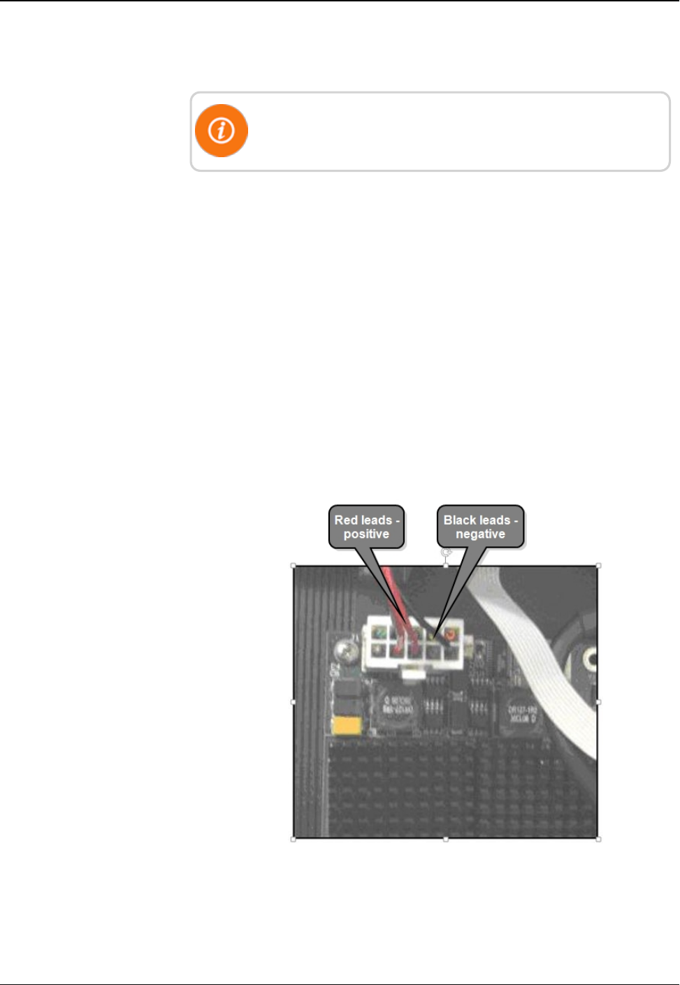
Figure 39 – Red and Black Leads
50 R450 Rack Mount DC Installation and Maintenance Guide
Chapter 5: Troubleshooting
5. Use the Digital Volt-Ohm-Multimeter to measure the voltage. The
red leads are positive; the black leads are negative.
6. The voltage must be between 4.9V and 5.2V. Turn off the
R450 RM DC circuit breaker.
If the voltage is above or below these values, it indicates that the
power supply is defective. Return the R450 RM DC to Neptune's
repair facility.
7. Reconnect CPU power.
Verifying Radio Power
1. Turn off the circuit breaker if it is not already off.
2. Remove the BATT connector on the radio. The locking ring
unscrews.
3. Turn the circuit breaker back on.
4. On the power cable connector, measure the voltage across pins X
and Y as shown.
5. The voltage should be between 14.5V and 15.5V. If the voltage is
above or below these values, the power supply is defective and the
R450 RM DC should be returned to Neptune's repair facility.
6. If the voltage is within specifications, turn the circuit breaker off
and replace the connector. Make sure that the connector locking
ring is finger tight.
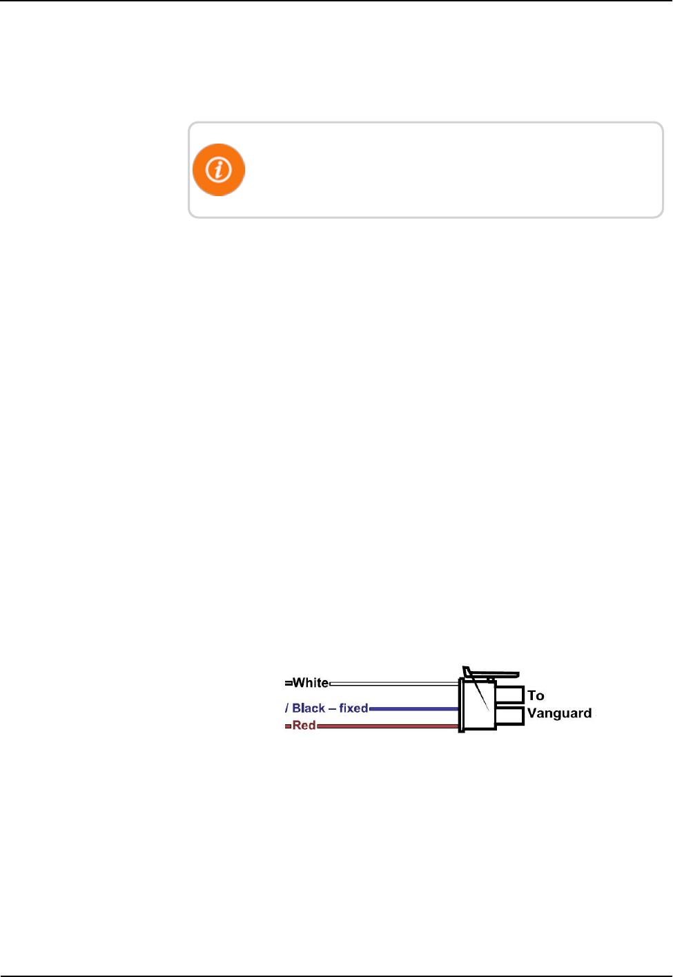
Verifying Cellular Modem Power
Cal Amp Vanguard Modem
Approximately 12.0 V should be present between the two pins shown
as illustrated in the following figure.
Figure 40 – Vanguard Three Wires
R450 Rack Mount DC Installation and Maintenance Guide 51
Chapter 5: Troubleshooting
Verifying Cellular Modem Connectivity
Cal Amp Vanguard Modem
To verify connectivity and signal levels, complete the following.
1. Locate the RSSI LED light on the modem.
2. Identify how the light is lit.
lSolid = indicates signal strength is strong
lBlinking = indicates signal strength is medium
lOff = indicates signal strength is poor or no signal at all
Figure 41 – CalAmp Vanguard Modem with RSSI LED
3. If the signal strength is poor or if there is no signal at all, there is
something wrong with the antenna, or it is possible that the local
cell service is not working.
For more detailed information on your wireless connection status,
connect to the modems configuration application. Refer to
"Securing the R450 RM DC" on page 27.
Ethernet
If Ethernet backhaul is used, then check the status lights on the CPU
board. Refer to "Testing the Connections" on page24.
52 R450 Rack Mount DC Installation and Maintenance Guide
Chapter 5: Troubleshooting
Verifying Radio Functionality Using an MIU
To verify that the system is functioning properly, complete the
following steps.
For this test to be valid, there must be regular time beacon
transmissions sent by the R450 RM DC. This is indicated by the
TX indicator flashing every ten seconds. See Figure 37 on page
48. If the R450 RM DCis not sending out time beacons, this test
will automatically fail.
1. Obtain a magnet and an MIU.
2. Swipe the MIU with a magnet so that it will send out a
configuration packet.
3. Watch for the radio's Busy light to turn on. This should happen
within a minute of swiping the MIU.
lIf the Busy light turns on, it should be followed by an
immediate flash of the TX indicator. See Figure 41 on page 52.
lIf the Busy indicator is not immediately followed by a flash of
the TX indicator, then there is an internal problem with the
R450 RM DC that may include its configuration, the radio,
NTG modem, or the computer.
R450 RM DC is Syncing but Not Supplying MIU Data
If the R450 RM DC is online, this indicates that the computer and the
backhaul modem are both working. If no readings are being collected
by the R450 RM DC, this indicates that there is a potential problem
with the radio and modem.
Troubleshooting this problem requires going to the R450 RM DC
site.
Initial Observations
After opening the cabinet, assess the following.
lThe R450 RM DC sends out a time beacon every 10 seconds. The
transmit light on the radio should flash every 10 seconds. See
Figure 37 on page 48. Only the red transmit light should turn on. If
the amber ALM indicator turns on at the same time, this indicates
that there is a problem between the transmitter and the antenna.
lIf the transmit indicator does not flash, this indicates that there is a
potential problem with the modem or possibly the computer's serial
port.
R450 Rack Mount DC Installation and Maintenance Guide 53
Chapter 5: Troubleshooting

Transmitter Transmits but ALM Indicator Flashes
This requires measuring the Voltage Standing Wave Ratio of the
antenna system. If the VSWR is greater than 1.5:1, that indicates that
there is a problem with the feed line or the antenna.
Measuring the VSWR
To measure the VSWR (MFJ-269 SWR Analyzer), complete the
following steps.
1. Make sure the red Power button is off. The red button is extended
outward.
2. Press the UHF button to be sure it is extended outward.
3. Turn the Frequency knob fully counter-clockwise. This knob
points to 114-170/UHF.
4. Connect the 2-inch long attenuator pad to the Antenna
Connector. Leave the other end open.
5. Press and lock the red Power button and the black UHF button.
6. Adjust the Tune knob for desired frequencies. Sweep the entire
450 - 470 MHz range.
7. Observe the indicated VSWR. It should read 3.0 ± 0.2
This indicates that the unit is calibrated correctly and the batteries
are good.
lIf the reading is outside this range, then try replacing the
batteries (eight AA batteries).
lIf this does not improve the readings, the unit needs to be
recalibrated.
8. Power off the unit.
9. Remove the attenuator pad and connect the antenna from the
bottom of the collector.
10. Press and lock the red Power button and the black UHF button.
11. Adjust the Tune knob for desired frequencies. Look at both the
collector receive and transmit frequencies.
12. Observe the indicated VSWR. The value should be 1.5 or less.
A value of 1.0 is ideal but not practical. Usually values are 1.1 or
1.2.
If a flashing SLP indication appears in the bottom-right corner of
the display, this indicates Sleep mode. Simply turn the unit off and
then on again.
54 R450 Rack Mount DC Installation and Maintenance Guide
Chapter 5: Troubleshooting

13. When finished, power off the unit.
The Radio Never Transmits
The simplest test is to cycle power on the R450 RM DC to see if the
radio starts transmitting.
It can take up to 10 minutes for the R450 RM DC to be fully
functional.
lIf radio starts transmitting, this indicates that there was a soft failure
in one of the serial ports possibly related to the side effects of a
storm.
lIf this does not fix the problem, then the R450 RM DC has an
internal problem, either with the computer or the Neptune modem.
It is recommended that you return the R450 RM DC for repair.
Reduction in Amount of Data Collected
If the R450 RM DC is not collecting as much data as before, but it is
still collecting some MIU data, this usually indicates that there is a
problem with the antenna and feedline system or possibly an internal
problem. To determine the cause of the problem, complete the
following steps.
1. Check all the system voltages as outlined above.
2. Check the VSWR of the system using the technique previously
described.
If the VSWR is high, the feedline and antenna should be checked
out and certified by qualified radio personnel.
3. Check the VSWR again, if the power output is low, by placing the
wattmeter between the duplexer and the surge protector.
If the VSWR measures much higher before the surge suppressor,
the suppressor may be damaged.
If the above tests pass, most likely there is s problem with the
duplexer or radio, and it is recommended that you contact Customer
Support
R450 Rack Mount DC Installation and Maintenance Guide 55
Chapter 5: Troubleshooting

Contacting Customer Support
Within North America, Neptune Customer Support is available
Monday through Friday, 7:00 AM to 5:00 PM Central Standard Time
by telephone, email, or fax.
By Phone
To contact Neptune Customer Support by phone, complete the
following steps.
1. Call (800) 647-4832.
2. Select one of the following options:
lPress 1if you have a Technical Support Personal Identification
Number (PIN).
lPress 2if you do not have a Technical Support PIN number.
3. Enter the six-digit PIN number and press #.
4. Select one of the following options.
lPress 2for Technical Support.
lPress 3for maintenance contracts or renewals.
lPress 4 for Return Material Authorization (RMA) for Canadian
accounts.
You are directed to the appropriate team of Customer Support
Specialists. The specialists are dedicated to you until the issue is
resolved to your satisfaction. When you call, be prepared to give
the following information.
lYour name and utility or company name.
lA description of what occurred and what you were doing at
the time.
lA description of any actions taken to correct the issue.
By Fax
To contact Neptune Customer Support by fax, send a description of
your problem to (334) 283-7497. Please include on the fax cover sheet
the best time of day for a customer support specialist to contact you.
By Email
To contact Neptune Customer Support by email, send your message to
support@neptunetg.com.
56 R450 Rack Mount DC Installation and Maintenance Guide
Chapter 5: Troubleshooting
R450 Rack Mount DC Installation and Maintenance Guide 57
Appendix A: RF Antenna Installation
RF Antenna Overview
There are a number of critical items you must consider when placing and installing the
antenna. The following list contains items that can influence the antenna placement and
installation.
Mounting the Antenna
Consider the following when mounting the antenna.
1. Mount the antenna as high as possible with an unobstructed view of the coverage
area.
lThe supporting structure, if the antenna is not mounted above it, can cause
specific areas of limited coverage.
lWater towers in particular can severely limit coverage where the signal must pass
directly through the tank. When mounting the antenna on a water tower, it is
recommended that they be mounted on top as close to the center as possible.
lWhen mounting the antenna on a traditional three-leg or four-leg tower, the
standoff mount for the antenna must position the antenna at least five feet away
from the tower to minimize coverage area problems.
2. Avoid making the R450 Data Collector's (R450 RM DC) antenna the tallest point
in the surrounding area. This may be unavoidable but it increases the potential of
the antenna being damaged by lightning.
Mounting the Antenna Mast
Consider the following.
CAUTION: The antenna mast and stand must be grounded
to the same grounding electrode used for the building's
electrical system to ensure that all exposed, non-current-
carrying metal parts are the same potential. Refer to NEC
Article 810.
When mounting the antennas and antenna mast, it is important to
maximize the line-of-sight relationship between the RF 450 MHz
Antenna and R450 MIUs for optimum RF communications.

WARNING: Antenna contact with high voltage wires may
result in death. Watch for overhead electric power lines
when erecting the antenna and mast.
WARNING: Do not mount antennas on utility poles, electric
service masts, or other structures carrying electric light or
power wires. Coaxial cables must maintain clearance of at
lease 2 feet (.61 M) from power or light wires of less than
250V, or at least 10 feet (3.048 M) from power wires of more
than 250V, per N.E.C., Article 810, C.E.C. Section 54.
Site Recommendations
The following are recommendations for sites with multiple transmitters, receivers, and
antennas. These sites require extra care when determining a location to install the
antenna.
lAvoid mounting the R450 RM DC antenna so that it is at the same height as
another antenna on the site, regardless of the frequencies.
lFor sites that have multiple antennas, if possible, mount the antennas one above the
other, separating each by at least 10 feet vertically. This will minimize the
interference between the systems.
lThe exception to the previous rule is for cellular antennas. As long as the
R450 RM DC antenna is either above, below, or in the middle of the ring of cell
antennas, the two systems can coexist without interference.
lAntenna sites that must share space with multiple transmitting systems may require
additional equipment to protect the systems from interfering with each other. These
sites may also require additional engineering to make them perform well.
58 R450 Rack Mount DC Installation and Maintenance Guide
Appendix A: RF Antenna Installation
lIf there are radio systems at the site that are already operating on
the 450 - 470 MHz band, it may be advantageous to combine the
signals into one antenna system using the appropriate equipment.
This often works better than attempting to protect the individual
systems from interfering with each other.
lManaged antenna sites may require additional equipment and may
dictate how an installation is to be performed. As long as the
installation meets Neptune's minimum requirements, following the
site's requirements is recommended.
Feed Line and Antenna Recommendations
CAUTION: Neptune recommends that you consult with a
qualified installer on the design and installation of the
antenna systems. If the installer is already familiar with the
sites and the existing equipment, this can make the
installation go more smoothly.
Feed Line
The feed line is a significant contributor to both good and poor system
performance. A properly installed feed line is critical to optimal
system performance. Testing the antenna while it is on the ground can
ensure the system is working properly.
Installation of the connectors is best done with the proper tools and a
trained installer. With the proper tools and jigs, installing coaxial
(coax) connectors takes only a few minutes each. Not using the proper
tools as recommended by the manufacturer could potentially cause
problems, either immediately or after several years of apparently proper
operation.
Feed Line Requirements
Consider the following.
lThe antenna and feed line system installation must be certified by
the installer after it is completed to perform according to
specifications.
lMaximum loss for the feed line and connectors must be less
than 3 dB.
lThe feed line must be bonded at the top of the tower and at the
base of the tower. Andrew grounding kits and procedures should be
used for all bonds.
R450 Rack Mount DC Installation and Maintenance Guide 59
Appendix A: RF Antenna Installation

lFor towers over 150 feet tall, the feed line should be bonded at
regular intervals down the tower. The general recommendation is
that the feed line be bounded by a minimum of 200 feet. Site
requirements and standard practices should dictate the
configuration.
lAn optional surge protector may be installed on the tower near the
antenna to help protect the feed line but is not required.
lFor the AVA5-50 cable or larger, jumpers should be used to go
between the larger cable and the R450 RM DC and antenna
connectors.
lAndrew provides installation instructions for Heliax Coaxial Cable.
See Bulletin 17800B Revision C. Neptune can supply a PDF copy
by request through Customer Support.
Cable Guidelines
Prepare the cable for installation and check for damage. You will need
the following materials to install the cable.
Action Material Needed
Hoisting the Cable lHoist lines
lPulleys
lCable reel
lHoisting grips
Anchoring Cable lCable hangers (standard, snap-in)
l3 to 4 ft. intervals
Grounding Coax ground kits (top, bottom, building entrance)
Horizontal Cable Runs lAbove ground - ice bridge
lBuried cable - conduit or sand below the frost line or one meter
Cable Connections lConnector installation instructions
lConnector torque
lWeatherizing kits
Measurements lReturn Loss (VSWR)
lDistance to Fault (DTF)
Table 10 – Material Needed for Cable Installation
60 R450 Rack Mount DC Installation and Maintenance Guide
Appendix A: RF Antenna Installation
Neptune Part Numbers
The following tables provides Neptune part numbers for cable and
connectors.
Neptune
Part
Number
Andrew
Part
Number
Coax
Diameter
Loss per
100'
Minimum
Bend
Radius
Weight
per Foot
Maximum
Length
Notes
10046-119 LDF4-50A 1/2" 1.45 dB 5" 0.15 150' Recommended
antenna cable
for 150' cable
runs or less
10046-118 AVA5-50 7/8" 0.74 dB 10" 0.30 400' Recommended
antenna cable
for runs over
150'
Table 11 – Neptune Part Numbers for Cable and Connectors
The following tables contain the Neptune part numbers for connectors
and accessories.
Cable Type Neptune Part
Number
Andrew Part
Number
Coax Diameter Notes
FSJ4-50B
10046-117 F4A-PNMDM-6-
USA
Pre-made Coax 6'
Jumper DIN Male
on one end, N
Male on the other
Used as jumper from feed line to
R450 RM DC or antenna
LDF4-50A
8138-200 L4TNM-PS Coax Connector,
N Male
Mates with R450 RM DC and
antenna connectors
SG12-12B2U SureGround
Grounding Kit for
1/2 " coax
AVA5-50
8138-190 ALDF-PS Coax Connector,
7/16" DIN Female
Used to connect to FSJ4 jumper
cable
Table 12 – Connectors and Accessories
For the long-term protection of all RF connections, use the appropriate
Andrews weatherproofing kit (Andrews P/N 245171) on all coaxial
connectors.
R450 Rack Mount DC Installation and Maintenance Guide 61
Appendix A: RF Antenna Installation

Antenna
General specifications for the supplied antenna are shown in the table
below.
Neptune P/N 12896-001
Andrew P/N DB636-C
Frequency Range 450-482MHz
Maximum Input Power (Watts) 500
Gain 8.1 dBi (6 dBd)
Bandwidth > 1.5VSWR 32 MHz
Vertical Bean Width (-3 db) 20 Degrees
Lightning Protection Direct Ground
Termination N Female
Overall Length 9.3 Feet
Element Housing Length 6.8 Feet
Support Pipe Diameter 2.5 inches
Support Pipe Length 26 Inches
Wind Load 1.61 Square Feet
Rated Wind Velocity 225 MPH
Weight 30 lbs
Mounting Hardware Included DB365 Clamps
Requirements
lThe antenna, if mounted on the side of a tower or other supporting
structure, must be mounted so that it is at least five feet away from
the structure. The components to offset the antenna are specific to
the installation and are not included by Neptune with the
R450 RM DC package.
lThe antenna is large and care must be taken when hoisting it up a
tower so that it is not damaged.
lThe feed line should not be attached to the antenna while it is
being hoisted up the tower or other supporting structure. The feed
line should be attached after the antenna is in place.
lThere have been reports of damage to the antenna's N connector
where the center pin has become bent and shorts out the antenna
system. Care must be taken not to damage the connector.
62 R450 Rack Mount DC Installation and Maintenance Guide
Appendix A: RF Antenna Installation
System Certification
The Andrews antenna supplied with the R450 RM DC is specified as
having a VSWR of 1.5:1 or better over the 450 - 470 MHz range.
Measuring VSWR at the R450 RM DC must take into account losses
in the feed line. For instructions, see “Measuring the VSWR” on page
68. The easiest approach is to use return loss instead of VSWR. The
1.5:1 VSWR translates into a return loss of 13.98dB. Refer to Table 13
below, Table 14 on the next pageand Table 16 on page70 to assist
with the calculation.
It is recommended that the feed line be certified as a separate step.
This is best performed by putting a known amount of power into one
end of the cable and verifying that, after correcting for the cable
losses, the correct amount of power is coming out the other end.
Power Measurement
Input Power
1W 5W 10W
Reflected Power Reading Return Loss VSWR
0.001 0.005 0.01 30.0 1.07
0.002 0.010 0.02 27.0 1.09
0.003 0.015 0.03 25.2 1.12
0.004 0.020 0.04 24.0 1.14
0.005 0.025 0.05 23.0 1.15
0.006 0.030 0.06 22.2 1.17
0.007 0.035 0.07 21.5 1.18
0.008 0.040 0.08 21.0 1.20
0.009 0.045 0.09 20.5 1.21
0.010 0.050 0.10 20.0 1.22
0.020 0.100 0.20 17.0 1.33
0.030 0.150 0.30 15.2 1.42
0.040 0.200 0.40 14.0 1.50
0.050 0.250 0.50 13.0 1.58
Table 13 – Power Measurement to Return Loss and
VSWR Conversion Table -Part I
R450 Rack Mount DC Installation and Maintenance Guide 63
Appendix A: RF Antenna Installation
Input Power
1W 5W 10W
Reflected Power Reading Return Loss VSWR
0.060 0.300 0.60 12.2 1.65
0.070 0.350 0.70 11.5 1.72
0.080 0.400 0.80 11.0 1.79
0.090 0.450 0.90 10.5 1.86
0.100 0.500 1.00 10.0 1.92
0.110 0.550 1.10 9.59 1.99
0.120 0.600 1.20 9.21 2.06
0.130 0.650 1.30 8.86 2.13
0.140 0.700 1.40 8.54 2.20
0.150 0.750 1.50 8.24 2.26
0.160 0.800 1.60 7.96 2.33
0.170 0.850 1.70 7.70 2.40
0.180 0.900 1.80 7.45 2.47
0.190 0.950 1.90 7.21 2.55
0.200 1.000 2.00 6.99 2.62
Table 13 – Power Measurement to Return Loss and
VSWR Conversion Table -Part I (continued)
Input Power
1W 5W 10W
Reflected Power Reading Return Loss VSWR
0.20 1.05 2.10 6.78 2.69
0.22 1.10 2.20 6.58 2.77
0.23 1.15 2.30 6.38 2.84
0.24 1.20 2.40 6.20 2.92
Table 14 – Power Measurement to Return Loss and
VSWR Conversion Table -Part II
64 R450 Rack Mount DC Installation and Maintenance Guide
Appendix A: RF Antenna Installation

Input Power
1W 5W 10W
Reflected Power Reading Return Loss VSWR
0.25 1.25 2.50 6.02 3.00
0.26 1.30 2.60 5.85 3.08
0.27 1.35 2.70 5.69 3.16
0.28 1.40 2.80 5.53 3.25
0.29 1.45 2.90 5.38 3.33
0.30 1.50 3.00 5.23 3.42
0.31 1.55 3.10 5.09 3.51
0.32 1.60 3.20 4.95 3.60
0.33 1.65 3.30 4.81 3.70
0.34 1.70 3.40 4.69 3.80
0.35 1.75 3.50 4.56 3.90
0.36 1.80 3.60 4.44 4.00
0.37 1.85 3.70 4.32 4.11
0.38 1.90 3.80 4.20 4.21
0.39 1.95 3.90 4.09 4.33
0.40 2.00 4.00 3.98 4.44
0.41 2.05 4.10 3.87 4.56
0.42 2.10 4.20 3.77 4.68
0.43 2.15 4.30 3.67 4.81
0.44 2.20 4.40 3.57 4.94
0.45 2.25 4.50 3.47 5.08
0.46 2.30 4.60 3.37 5.22
0.47 2.35 4.70 3.28 5.36
0.48 2.40 4.80 3.19 5.51
0.49 2.45 4.90 3.10 5.67
Table 14 – Power Measurement to Return Loss and
VSWR Conversion Table -Part II (continued)
R450 Rack Mount DC Installation and Maintenance Guide 65
Appendix A: RF Antenna Installation
Coax Cable Loss
Coax Type FSJ4-50B LDF4-50A AVA5-50 Coax Type FSJ4-50B LDF4-50A AVA5-50
Loss 100 ft. 2.31 dB 1.45 dB 0.744 dB Loss 100 ft. 2.31 dB 1.45 dB 0.744 dB
Length (ft.) Loss in dB Length (ft.) Loss in dB
10 0.231 0.145 0.074 210 4.851 3.045 1.562
20 0.462 0.290 0.149 220 5.082 3.190 1.637
30 0.693 0.435 1.223 230 5.313 3.335 1.711
40 0.924 0.580 0.298 240 5.544 3.480 1.786
50 1.155 0.725 0.372 250 5.775 3.625 1.860
60* 1.386 0.870 0.446 260 6.006 3.770 1.934
70* 1.617 1.015 0.521 270 6.237 3.915 2.009
80* 1.848 1.160 0.595 280 6.468 4.060 2.083
90* 2.079 1.305 0.670 290 6.699 4.205 2.158
100* 2.310 1.450 0.744 300 6.930 4.350 2.232
110 2.541 1.595 0.818 310 7.161 4.495 2.306
120 2.772 1.740 0.893 320 7.392 4.640 2.381
130 3.003 1.885 0.967 330 7.623 4.785 2.455
140 3.234 2.030 1.042 340 7.854 4.930 2.530
150 3.465 2.175 1.116 350 8.085 5.075 2.604
160 3.696 2.320 1.190 360 8.316 5.220 2.678
170 3.927 2.465 1.265 370 8.547 5.365 2.753
180 4.158 2.610 1.339 380 8.778 5.510 2.827
190 4.389 2.755 1.414 390 9.009 5.655 2.902
200 4.620 2.900 1.488 400 9.240 5.800 2.976
* Acceptable Range
Table 15 – Coax Cable Loss Table
66 R450 Rack Mount DC Installation and Maintenance Guide
Appendix A: RF Antenna Installation

VSWRCalculation
Neptune recommends the following method of computing VSWR.
Taking the reading at the R450 RM DC end of the feed line without
compensating for cabling losses may give a false impression of the
antenna and feed line performance.
Using a Wattmeter and a Handheld 450MHz Radio
The recommended procedure is to use a handheld commercial grade
transceiver that is tuned to the R450 RM DC's transmitter frequency
and an inline wattmeter, such as a Bird Model 43 Wattmeter with the
appropriate element (slug) for the frequency range and power output of
the transceiver.
The Bird Model 43 Wattmeter uses elements to set the frequency and
power ranges that the meter will read. The wattmeter element should
be a 400 - 1000 MHz model sized so that the forward power reading
is close to full scale. For a 5W output handheld, the Bird 5E element
is recommended. If the radio puts out more than 5W, a Bird 10E or
higher power element may be required.
Complete the following steps to use a Wattmeter and handheld to
calculate VSWR.
1. Connect the wattmeter and transceiver to the feed line in place of
the R450 RM DC.
2. Measure both the forward and reflected power.
3. Find the return loss value using Table 13 on page63 and Table 14
on page64.
4. Find the loss attributed to the coax using Table 15 on the previous
page based on the coax type and feed line length.
The adjusted return loss is calculated by the following formula.
Return Loss (fromTable) - (2 x Cable Loss) = Corrected Return
Loss
5. Find the VSWR using Table 13 on page63 and Table 14 on
page64 using the Corrected Return Loss value.
6. Change the frequency on the handheld transceiver to the
R450 RM DC's receive frequency.
7. Measure the power and calculate VSWR using the procedure just
used for calculating transmitter VSWR.
8. Record both transmit and receive frequencies' VSWR values. In
order for the antenna system to pass, both readings must be less
than 1.5.1.
R450 Rack Mount DC Installation and Maintenance Guide 67
Appendix A: RF Antenna Installation
Using the AEA 140-525 Antenna Analyzer
Complete the following steps to configure the analyzer.
This procedure assumes that the analyzer has not been configured
prior to use.
1. Turn the analyzer ON.
2. Type the frequency: 46000.
3. Press Enter.
4. Set the value next to WID on the screen to 20 using the width
buttons.
5. Set the reading to return loss by pressing F1 three times. (Press it
slowly; the unit should beep each time.)
Taking the Reading and Calculating VSWR
1. Connect the analyzer to the feed line in place of the R450 RM
DC.
2. Configure the analyzer using the preceding procedure.
Be sure that there is not a vertical line running through the display
in the plot area. If there is, press EXAM PLOT and it should go
away.
3. Allow the analyzer reading to stabilize, between 10 and 20
seconds.
4. Press EXAM PLOT to freeze the display.
5. Move the cursor (the vertical line in the middle of the screen)
using the FREQ arrows to approximately the R450 RM DC's
frequency. (It moves to within 100KHz of a frequency.)
6. Read the value next to RETL on the display. This is the return
loss value.
7. Find the loss attributed to the coax (based on the coax type and
feed line length) using Table 15 on page66.
8. Calculate the adjusted return loss using the following formula.
Return Loss (from Table 5) - (2 x Cable Loss) = Corrected
Return Loss.
9. Find the VSWR (using the Corrected Return Loss value) Table 13
on page63 or Table 14 on page64
68 R450 Rack Mount DC Installation and Maintenance Guide
Appendix A: RF Antenna Installation
10. Move the cursor to within 100KHz of the R450 RM DC's receive
frequency.
11. Calculate VSWR using the new return loss value.
12. Record both values. They must be less than 1.5.1 for the antenna
and feed line to pass the test.
General Installation Guidelines
Unpacking
As with all precision electronic instruments, the RF 450 MHz antenna
should be handled with care; however, no additional special handling
is required.
After unpacking the RF 450 MHz antenna, inspect it for damage. If
any parts of the R450 MHz antenna appear to be damaged or prove to
be defective upon installation, notify your Neptune sales
representative. If the unit or item requires reshipment, use the original
cardboard box and packing material.
In particular, check to be sure that the N connector at the base of the
antenna is not damaged. This is much easier to check while the
antenna is on the ground than after it is installed.
RF Antenna Installation Kit
The RF 450 MHz antenna and the basic accessories are included with
the R450 RM DC. The mounting brackets that are included are
designed to mount on the top of a mast or similar structure. If the
installation requires offsetting the antenna from the supporting
structure, this must be ordered separately. Neptune does not sell it.
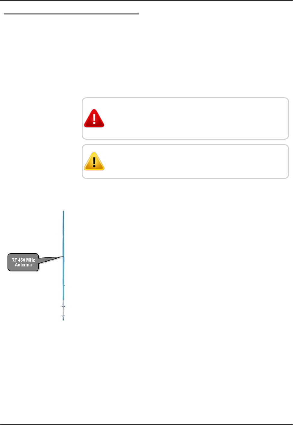
Figure 42 – RF 450 MHz Antenna
R450 Rack Mount DC Installation and Maintenance Guide 69
Appendix A: RF Antenna Installation

Tools and Materials
Table 16 shows the recommended tools and materials you need to
successfully install the RF antenna.
Item Description/Recommendation Use
Took Kit Contains standard tools
including:
lAssorted screwdrivers
(medium, flat head)
lCordless electric
drill/assorted bits
lAdjustable wrench
lStandard socket wrench set
lStandard box-end wrench set
lHammer
lChannel locks
Various installation procedures
performed by the installer
UV-Stable Cable Ties 8" and 12"
(20.32 cm and 30.48 cm)
Secure coax cable
Cable Clips Various sizes Securing coax cable
Weatherizing Kit PolyPhasor P/N: WK-1
- or
Times Microwave P/N: WK-S-2
- or
Andrews P/N: 245171
Weatherproofing coax cable
connections
Electrical Tape Scotch®Heavy Duty Vinyl
Electrical Tape 22
-or
Scotch®Super 88
Weatherproofing coax cable
connections and other connections
as required
Table 16 – Recommended Tools and Materials
70 R450 Rack Mount DC Installation and Maintenance Guide
Appendix A: RF Antenna Installation
Installing the RF Antenna
This section contains the instructions for the RF antenna installation.
Mounting the RF 450 MHz Antenna
The RF 450 MHz antenna must be installed by professionals in
accordance with the FCC site license before you begin the installation
of the R450 RM DC.
WARNING: Mounting and wiring the RF 450 MHz antenna
must be done by a trained professional. Be sure to
subcontract this work, so it is completed properly.
CAUTION: The cable, connectors, and the antenna
installation must be checked with the VSWR meter.
To mount the RF 450 MHz antenna, complete these steps.
1. Assemble the RF 450 MHz antenna, per the instructions
included with the antenna kit See Figure 43.
2. Use the mounting hardware included with the antenna to mount
the antenna per the supplied instructions.
3. Install the antenna in accordance with the FCC site license (per
the antenna mounting instructions contained in this appendix).
4. Weatherize the antenna coaxial connector using the
weatherizing kit. See Table 16 on the previous page.
Figure 43 – RF 450 MHz Antenna to be Mounted
Mounting the Antenna Mast to the Building
With a wall-mount installation, it is necessary to mount the 450MHz
and cellular antenna on the exterior of the building. Complete the
following steps to mount the antenna mast to the building. Use
manufacturer installation instructions provided with mounting
hardware.
R450 Rack Mount DC Installation and Maintenance Guide 71
Appendix A: RF Antenna Installation
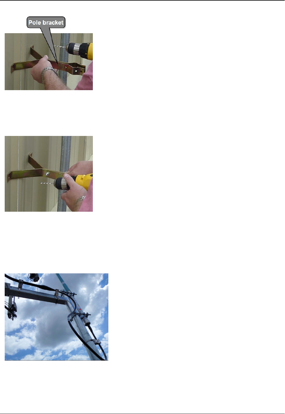
1. Use antenna pole brackets to install the pole to the building.
See Appendix A.
2. With a drill, pre-drill your holes for the first pole bracket.
3. Secure the pole bracket in one of the following ways:
lIf mounting to a wood-constructed wall, use wood screws
rated at minimum of 20 pounds loading.
lIf mounting to sheet metal or masonry, use appropriate sheet
metal screws or masonry anchors rated at a minimum of 20
pounds loading.
Figure 44 – Securing the Pole Bracket
4. Place the antenna mast pole within the bracket.
5. Using a level to make sure the pole is vertical, line up a second
bracket a minimum of 2 feet (2') from the bracket you just
installed.
6. Secure the second bracket similarly to the first one, following
steps 2 and 3.
7. Line up the pole in the two brackets. See Appendix A.
8. Secure the pole with the bolts provided.
Figure 45 – Lining Up Second Bracket
Attaching the RF 450 MHz Antenna Cable
To attach the RF 450 MHz antenna cable to the RF antenna
R450 RM DC, complete the following steps.
1. Locate the RF 450 MHz antenna cable that extends from the
RF 450 MHz antenna cable conduit. See Figure 46.
2. Connect the RF 450 MHz antenna cable to the RF 450 MHz
antenna connector located on the bottom of the R450 RM DC.
See Appendix A. Tighten the coaxial connector to:
lType N: 15 to 20 lbf in (1.7 - 2.3 N m)
lType 7 - 16 DIN: 220 - 265 lbf in (25 - 3 N m)
Figure 46 – RF 450 MHz Antenna Connection
72 R450 Rack Mount DC Installation and Maintenance Guide
Appendix A: RF Antenna Installation
WARNING: Special consideration should be given when the
RF antenna R450 RM DC is installed inside a building.
The screen (shield) of the coaxial cable must be connected
to the earth (grounded) at the entrance to the building. This
should be done in accordance with applicable national
electrical installation codes (Section 820.93 of the National
Electrical Code, ANSI/NFPA 70).
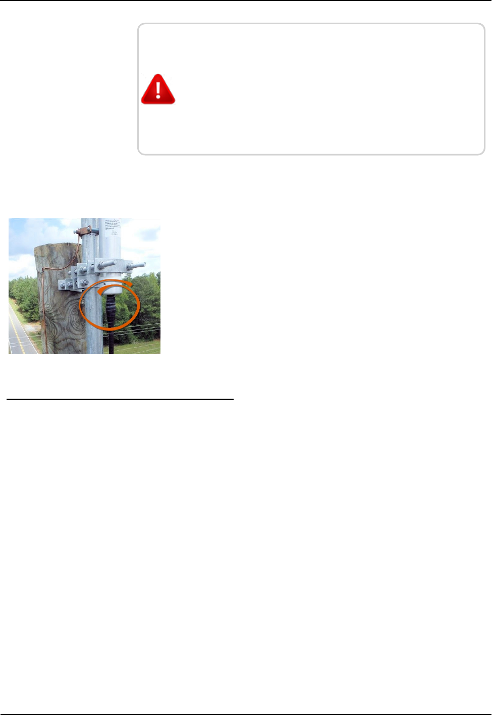
Weatherizing the Cable Connections
Complete the following instructions to weatherproof the cables with
the Scotch Wireless Wk101 Kit or equivalent.
1. Using the weatherizing kit, start the tape at the top of the RF
antenna connection as illustrated in Figure 47.
2. Wrap the tape around the connection several times; slowly work
your way downward to weatherize your connection at the base.
Figure 47 – Weatherizing the RF Antenna Connection
Troubleshooting the RF Antenna
This section provides a table of possible symptoms, areas of focus, and
actions that can be taken to try to resolve problems that could arise
with your RF antenna.
Equipment Required
The following items are required in order to troubleshoot the
R450 RM DC.
lKeys to access the site and open the R450 RM DC cabinet
lDigital volt - Ohm multimeter
lSocket and open-end wrenches to install and remove the
R450 RM DC
lSmall, medium, and large slot-style screw drivers
l#1 and #2 Phillips head screw drivers
lElectrical tape and wire ties
lSpare R450 RM DC in order to swap if one fails
R450 Rack Mount DC Installation and Maintenance Guide 73
Appendix A: RF Antenna Installation

lR450 RM DC configuration memory stick
lAnti-static wrist strap and ground lead with alligator clip for
attaching wrist strap to the R450 RM DC cabinet
lMIU configured for the site
lMagnet to swipe the MIU
Conduct a test by hooking up the wattmeter to the coaxial connector
at the R450 RM DC end to measure the VSWR for the antenna and
feed line combined.
The R450 RM DC's transmitter cannot be used to certify the antenna
system. The transmitter only transmits short packets approximately
50ms in length, so taking an accurate reading of forward or reflected
power cannot be done with standard equipment.
74 R450 Rack Mount DC Installation and Maintenance Guide
Appendix A: RF Antenna Installation
R450 Rack Mount DC Installation and Maintenance Guide 75
Appendix B: USB Flash Drive Configuration for R450 RM DC
Overview
This appendix provides information and the steps for creating an
R450 Rack Mount Data Collector (R450 RM DC) and configuring the USB flash drive
using the N_SIGHT PLUS host software.
Creating a Collector
The Collector tab in the N_SIGHT PLUS host software provides valuable information
about the R450 RM DCs in your R450 System. On this tab you can search for or create
a R450 RM DC.
Using the Collector tab, you can do the following:
lCreate collector
lSearch collectors
Creating a New Collector
To create a new R450 RM DC, complete the following steps.
1. Open the N_SIGHT PLUS host software on the PC.
2. Select the Collector tab, and click Create Collector.
The Create a New Collector window appears similar to Figure 48. All required
fields display a red *.
Figure 48 – Create a New Collector Window
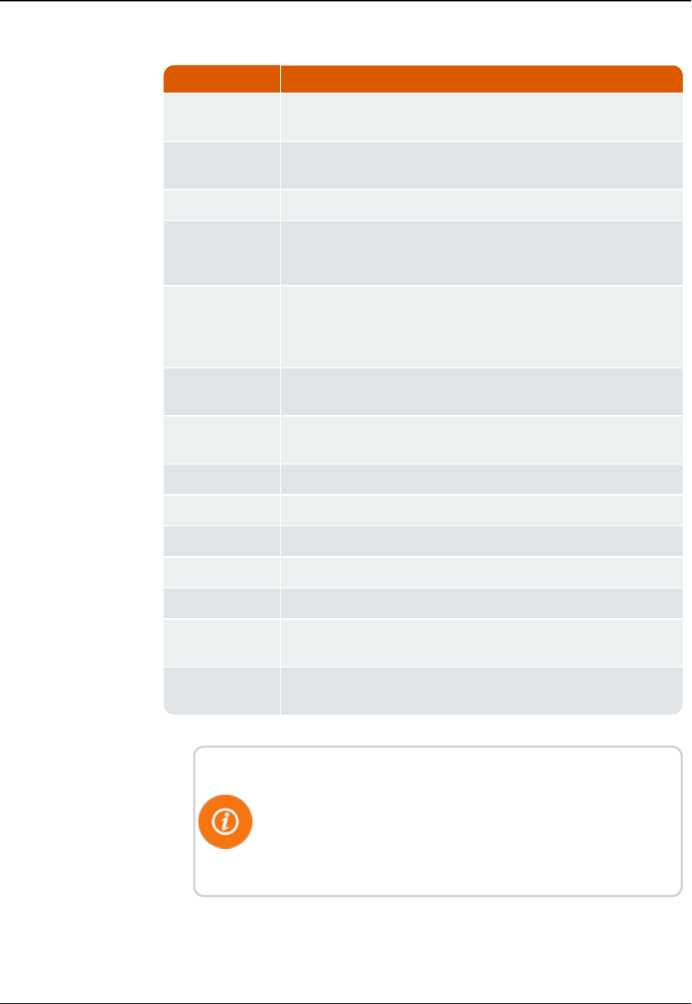
Field Description
Collector ID Indicates the unique identifier for the data collector which can be
a street, location, or a neighborhood.
Collector Name Indicates the name of the data collector, for example the street,
neighborhood, tower name, and so forth.
Host IP Address Displays the static IP address for the host database.
Time Zone Indicates the unique identifier for the time zone in which the
R450 RM DC is located; offset is fromUTC: Atlantic Time is -4;
Eastern Time is -5; and so forth.
Sync Interval
(minutes)
Indicates, in number of minutes, the time between
synchronizations between the collector and the database. Usually
it is 60 minutes for cellular system, and 30 minutes for an
Ethernet system.
Transmit
Frequency
Indicates the frequency used to transmit data.
Receive
Frequency
Indicates the frequency used to receive data.
Latitude Indicates the actual latitude of the R450 RM DC.
Longitude Indicates the actual longitude of the R450 RM DC.
Power Indicates the power used by the R450 RM DC.
Antenna Height Indicates the actual height of the RF antenna.
Daily Reboot Indicates if the R450 RM DC requires a daily reboot.
Start Time Displays the beginning time in hh:mm format for the quiet time
period when the R450 RM DC is not transmitting or receiving.
End Time Displays the ending time in hh:mm format for the quiet time
period when the R450 RM DC is not transmitting or receiving.
Table 17 – Collector Details
On this tab, remember the following:
lAll fields with an *are required.
lAll white fields are available fields.
lAll fields with gray text are read-only fields
76 R450 Rack Mount DC Installation and Maintenance Guide
Appendix B: USB Flash Drive Configuration for R450 RM DC
3. Complete all the required and available information that applies,
and click Save.
The Collector Network Settings tab appears similar to Figure 49.
Figure 49 – Collector Network Setting Tab
Field Description
WAN Connection Type Indicates the type of Wide Area Network (WAN) used by
the R450 RM DC. The options include the following:
lCellular
lCellular_Ethernet
lNetwork_DHCP
lNetwork_Static_IP
lMobile
NTP Server Indicates a server that uses NTP (Network Time protocol).
Its purpose is to keep the clock accurate.
Primary DNS Server Indicates the primary server, the first DNS (Domain Name
System) server queried when trying to resolve a server
name. You can supply the name rather than the
IPaddress, for example, Chicago rather than 10.10.10.10.
Secondary DNS Server Indicates the secondary server, the second DNS (Domain
Name System) server.
Table 18 – Collector Network Settings
R450 Rack Mount DC Installation and Maintenance Guide 77
Appendix B: USB Flash Drive Configuration for R450 RM DC
On this tab, remember the following:
lAll fields with an * are required.
lAll white fields are available fields.
lAll fields with gray test are read-only fields.
4. Complete all the required and available information that applies,
and click Save.
The R450 RM DC just created appears in the list of R450 DCs on
the Collector tab, and the detail appears in the lower half of the
page.
Editing Collector Information
To edit information for an R450 RM DC, complete the following
steps.
1. On the Collector tab, select the R450 RM DC for which you want
to edit the information.
The Edit Collector window appears with the existing information
for the collector.
2. Edit and change the appropriate information on both the Collector
Details tab and the Collector Network Settings tab.
3. When complete, click Save to display the new information for the
collector.
The changes you made are saved for the selected collector.
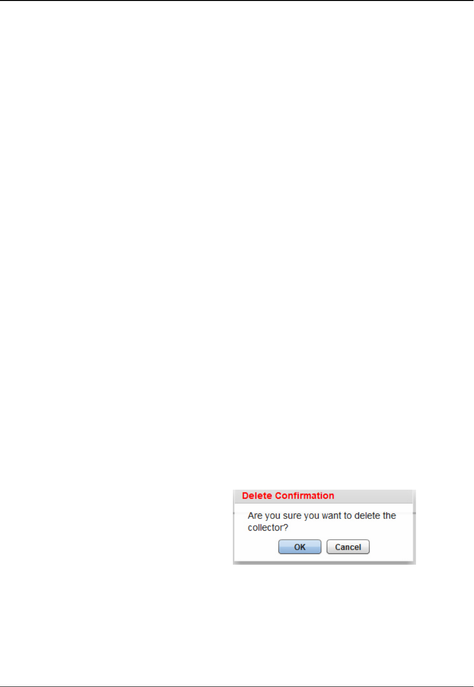
Deleting a Collector
To delete a collector, complete the following steps.
1. On the Collector tab, select the collector you want to delete.
2. Click Delete.
A delete confirmation message appears similar to the following.
Figure 50 – Delete Confirmation Dialog Box
3. Click OK.
The R450 RM DC is now deleted from the list of collectors on the
Collector tab.
78 R450 Rack Mount DC Installation and Maintenance Guide
Appendix B: USB Flash Drive Configuration for R450 RM DC
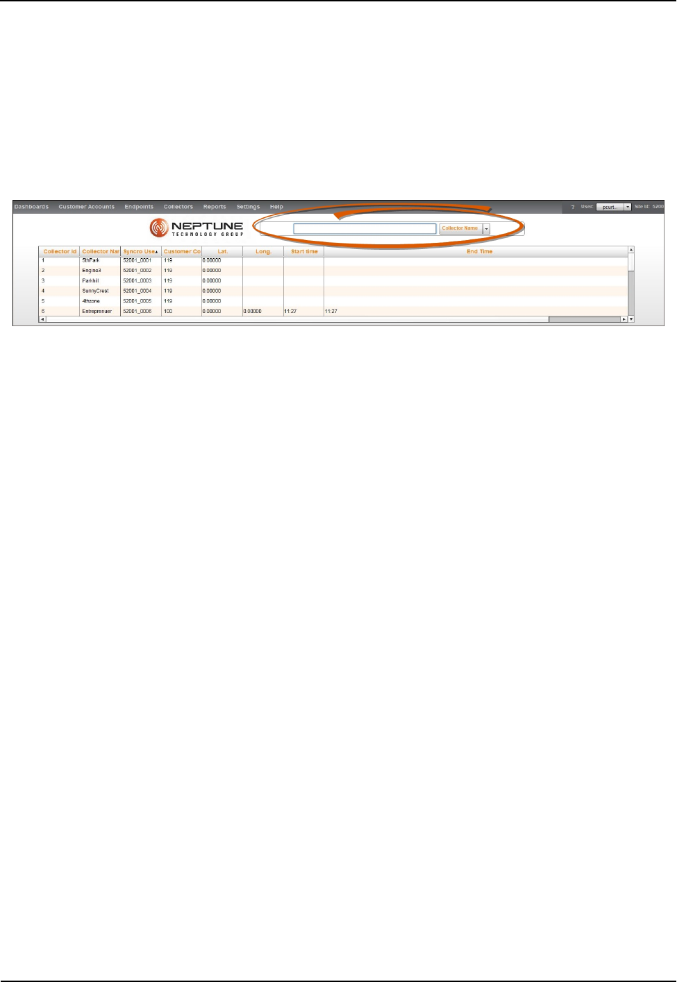
Using Collector Search
To use the Search function to locate an R450 RM DC, complete the
following steps.
1. Click Search Collectors on the Collector tab.
The following page appears.
Figure 51 – Collector Search
On this page, there is a drop-down selection list for you to select
how you want to search for the R450 RM DC.
lCollector Name
lSynchro User
lCollector ID
2. Type all or part of the search criteria you selected in the previous
step in the search area provided. See Figure 51.
Everything matching your search criteria appears in the collector
list on the Collector tab with the detailed information for the
collector appearing in the lower-half of the page. See Figure 52 on
page 80.
R450 Rack Mount DC Installation and Maintenance Guide 79
Appendix B: USB Flash Drive Configuration for R450 RM DC
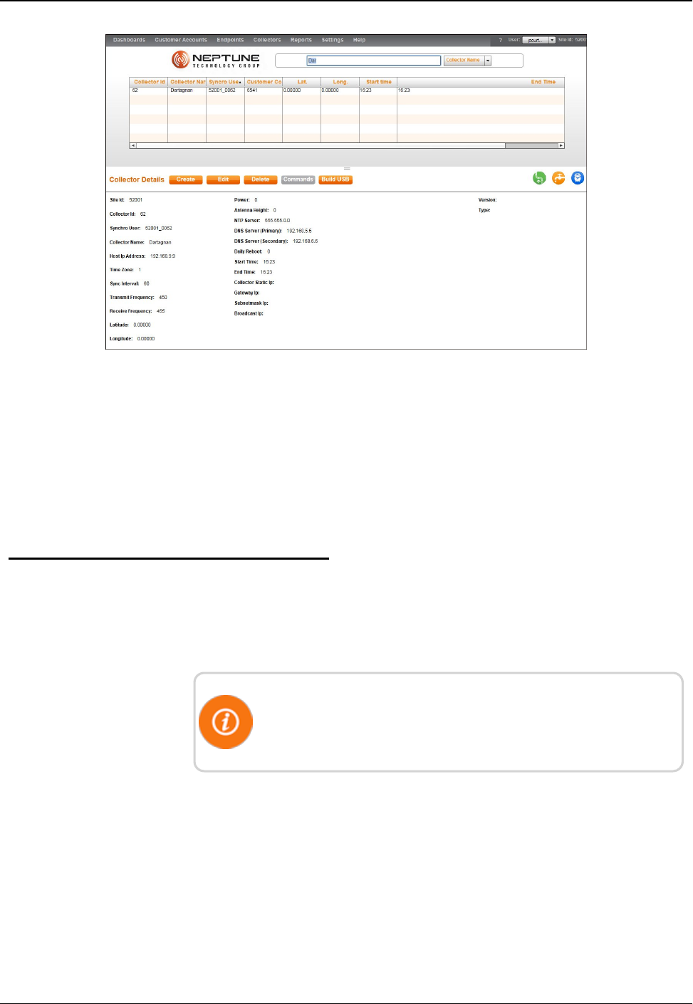
Figure 52 – Collector Search Results
3. Select one of the following options.
lCreate another R450 RM DC.
lEdit information for the selected R450 RM DC.
lDelete the selected R450 RM DC.
lBuild a USB drive for the R450 RM DC.
Building a USB Drive for Collector Configuration
This feature adds the ability to build a USB drive that can be inserted
into a replacement collector for automatic configuration in order to
mimic an old collector.
R450 Collector configuration application must be installed on a
local PC to extract files to the USB drive. Make sure only the
desired USB drive is on the computer.
80 R450 Rack Mount DC Installation and Maintenance Guide
Appendix B: USB Flash Drive Configuration for R450 RM DC
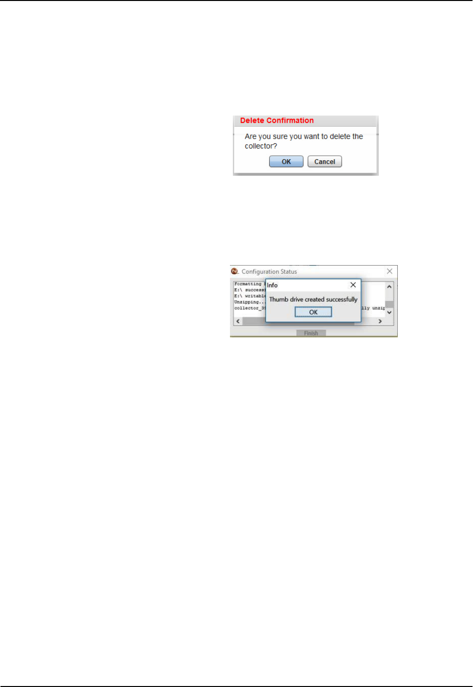
Complete the following steps to add an USB drive.
1. Select the R450 RM DC to uploaddata to the USBdrive from the
Collector tab
2. Click Build USB.
A confirmation message appears similar to the following.
3. Click OKto build the drive.
4. Double-click the downloaded file (*.ntg).
The application formats and extracts files to the USBdrive. A
message similar to the following will appear.
R450 Rack Mount DC Installation and Maintenance Guide 81
Appendix B: USB Flash Drive Configuration for R450 RM DC

This page intentionally left blank.
Appendix B: USB Flash Drive Configuration for R450 RM DC
82 R450 Rack Mount DC Installation and Maintenance Guide
R450 Rack Mount DC Installation and Maintenance Guide 83
Appendix C: Ethernet Termination
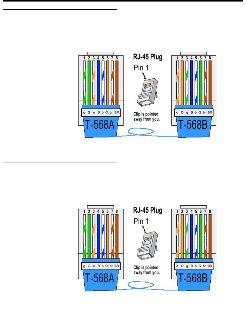
Straight-Through Ethernet Cable
For most installations, the Straight-Through Ethernet Cable is used. Terminate the
Ethernet cable according to the diagram below using the T-568B wiring standard for
both ends. One end should already be pre-terminated to the switch or hub.
Figure 53 – Straight-Through Ethernet Cable
RJ-45 Crossover Ethernet Cable
On some occasions, a Crossover Ethernet Cable is required. If you require a cable to
connect two Ethernet devices directly together without a hub or when you connect two
hubs together, you will need to use a crossover cable instead.
Figure 54 – RJ-45 Crossover Ethernet Cable

Determining if You Need a Crossover Cable
One method of determining if you need a crossover cable is to plug
the Ethernet cable from the hub or modem into your laptop computer's
Ethernet port. If the laptop computer can communicate through the
Ethernet port, then the site probably requires a Crossover Ethernet
Cable to be compatible with the R450 Data Collector (R450 RM DC).
Symbol Wire Color
o White with orange stripe
O Solid orange
g White with green stripe
B Solid blue
b White with blue
G Solid green
br White with brown stripe
BR Solid brown
Table 19 – Cable Color Code Table
84 R450 Rack Mount DC Installation and Maintenance Guide
Appendix C: Ethernet Termination

Glossary
A
ALM
Alarm indicator.
AMI
Advance Metering Infrastructure. System that captures, stores, and provides to
the utility at frequent intervals detailed consumption and other information,
such as, usage, leak, and flow status, in order to support advanced
applications. These data can then be used to support a onsumer portal.
Furthermore, the mass of data generated by the system can feed an advanced
analytics system to convert it into actionable information that supports the
efficient management of the utility.
AMR
Automatic Meter Reading. The automated process of reading meters.
APN
Access Point Name.
B
ballast
Heavy material used to secure the stability of the equipment stand. For the
R450 System, concrete blocks are used for the ballast.
C
CDMA
Code Division Multiple Access. A channel-access method used by various
radio commumication technologies tha allows multiple users to be connected
over the same channel.
R450 Rack Mount DC Installation and Maintenance Guide 85

Glossary
D
Data Collector
R450 Data Collector (R450 DC). The physical equipment that houses
Neptune's N_SIGHT PLUS host software. The R450 DC is a device that
collects meter reading data from Neptune's absolute encoder register
interfacing with Neptune's R450 MIU and transmits the data for collection. This
unit receives the data for collection. This unit receives the data and stores data
to be downloaded through the host software.
DHCP
Dynamic Host Configuration Protocol.
I
IMEI
International Mobile Equipment Identifier.
L
LED
Light Emitting Diode.
M
MEID
Mobile Equipment Identifier.
MHz
Abbreviation for megahertz. One MHx represents one million cycles per
second.
MIU
Meter Interface Unit.
86 R450 Rack Mount DC Installation and
Maintenance Guide

Glossary
R
R450 System
R450 System is a fixed network AMI system for targeted applications allowing
a utility to conduct meter reading operations automatically ensuring maximum
collection of the data.
S
serial number
A unique identification number given to each product at the factory.
V
VSWR
Voltage Standing Wave Ratio. The ratio of the amplitude of a partial standing
wave at an antinode (maximum) to the amplitude at an adjacent node
(minimum) in an electrical transmission line.
R450 Rack Mount DC Installation and Maintenance Guide 87

This page intentionally left blank.
88 R450 Rack Mount DC Installation and Maintenance Guide
Glossary

A
AC
power box 21
power source 21
activating light 25
activating, R450 DC 21
ALM
indicator 53
LED 48
antenna 62
accessories 12
analyzer 68
attaching 16, 18
cable 16
commerical broadcast 7
connection 16
external 4
GPRS 8
installing 71
mast 3
placement 6
RF 57
assembly accessories
Ethernet 9
GPRS 8
AWG 17
B
backhaul
modem 48
modem connectivity 52
type 2
battery 35
safety checklist 36
spill kit 36
bonded 59
C
cable
clips 13
Ethernet 83
Cal Amp, landcell modem 48, 51
calculating VSWR 68
cellular antenna 58
certification 63
circuit breaker 49
CIS 1
coax cable 8, 12-13, 60
coax cable loss 66
collector
building USB drive 80
create 75
deleting 78
details 76
edit information 78
network settings 77
R450 Rack Mount DC Installation and Maintenance Guide 89
Index

Index
using search 79
configuring
collector, USB flash drive 24
connectivity 52
connectors 61
conversion table 63-64
CPU board 24-25, 47, 50
creating collector 75
customer support 56
D
Digital Volt-Ohm-Multimeter 51
E
electrical codes 21
encoder register 1
Ethernet 9
backhaul 25
cable 22
cable, RJ-45 crossover 83
cable, straight-through 83
kit 9
parts list 9
port 84
termination 83
external ground lug 17
F
FCC 1
feed line 59
flash drive
configuration 75
frequencies 1
G
GPRS
modem 2
parts list 8
ground wire 17
component 16
connecting 17
H
host software 26
I
installation
common problems 7
completing 24
four types 2
instructions 15
kits 12
pole 5
R450 DC 3
site selection 3
interference 6
L
lightning arrestors 8
link integrity light 25
90 R450 Rack Mount DC Installation and Maintenance Guide

Index
M
magnet 14, 26, 53
materials 13
MIU 1
placement 7
swipe 26
modem
Cal Amp 46
GPRS 2, 8
mounting
antenna 17, 57
pole 39
RF 450 antenna 71
UPS 39
mounting brackets 69
N
NTP server 77
P
part numbers 61
parts list
Ethernet 9
GPRS modem 8
performance
maintaining 8
optimizing 6
pole
installation 5
mount 15
site 15
pole mounting
steel or concrete 39
power measurement 63
power supply 33
primary DNS server 77
R
R450 DC 1
kit 8
mounting 4
performance issues 6
potential problems 46
product description 1
securing 27
stand 5
transmitter 73
R450 MIU
performance issues 6
radio power 48
receiver
sensitivity 7
RF 450, antenna connection 72
RF antenna
installation kit 69
RF antenna, installation 57
S
secondary DNS server 77
server
NTP 77
R450 Rack Mount DC Installation and Maintenance Guide 91

Index
primary DNS 77
secondary DNS 77
signal strenght 52
SIM card 9
site
preparation 38
surveys 7-8
site, recommendations 58
SLP 54
specifications 11
electrical 11
environmental conditions 11
spectrum analyzer 7
stable ties 13
stand, R450 DC 5
storage 12
storm activity 8
structure 57
strut
channels 18
clamp 8
syncing 53
T
testing connections 24
tool kit 13
tools 13
tools and materials 70
tower 57
transceiver 67
troubleshooting 45
equipment required 45
PC Notebook Configuration 46
storm damage 46
voltage checks 49
tune knob 54
U
unlicensed equipment 6
unpacking 12
upacking 69
UPS 33
checklist 35
connecting 40
mounting 39
USB
building for collector configuration 80
flash drive 24-25
ports 24
V
VSWR 54, 63, 67
W
wall mounting 39
WAN connection 77
wattmeter 67
weatherizing
antenna connection 21
cable connections 20, 73
kit 13
92 R450 Rack Mount DC Installation and Maintenance Guide


Neptune Technology Group Inc.
1600 Alabama Highway 229
Tallassee, AL 36078
USA
Tel: (800) 633-8754
Fax: (334) 283-7293
Neptune Technology Group (Canada) Ltd.
7275 West Central Ave.
Mississauga, Ontario
L5N 5M9
Canada
Tel: (905) 858-4211
Fax: (905) 858-0428
Neptune Technology Group Inc.
Ejèrcito Nacional No. 418
Piso 12, Desp. 1201-1202
Col. Chapultepec Morales
Delegación Miguel Hidalgo
11570 Mèxico, Distrito Federal
T: (525) 55203 5294 / (525) 55203 5708
IM R450 RM DC 12.17 Part No. 12835-001 © Copyright 2006 - 2017, Neptune Technology Group Inc. Neptune is a registered trademark of Neptune Technology Group Inc.