Neptune Technology Group R450DC DATA COLLECTOR User Manual IM R450 Rack Mount DC
Neptune Technology Group Inc. DATA COLLECTOR IM R450 Rack Mount DC
Contents
- 1. 450-Rack Mount DC Manual 2
- 2. User Manaul Rack Mount DC
User Manaul Rack Mount DC

R450™ Rack Mount Data Collector
Installation and Maintenance Guide

R450™ Rack Mount Data Collector
Installation and Maintenance Guide
Copyright
This manual is an unpublished work and contains the trade secrets and
confidential information of Neptune Technology Group Inc., which are
not to be divulged to third parties and may not be reproduced or
transmitted in whole or part, in any form or by any means, electronic or
mechanical for any purpose, without the express written permission of
Neptune Technology Group Inc. All rights to designs or inventions
disclosed herein, including the right to manufacture, are reserved to
Neptune Technology Group Inc.
Neptune engages in ongoing research and development to improve
and enhance its products. Therefore, Neptune reserves the right to
change product or system specifications without notice.
Trademarks Used in this Manual
R450 Rack Mount Data Collector is a trademark of Neptune Technology
Group Inc. R450 is a trademark of Neptune Technology Group Inc. N_
SIGHT is a registered trademark of Neptune Technology Group Inc.
R450 System is a trademark of Neptune Technology Group Inc. Other
brands or product names are the trademarks or registered trademarks
of their respective holders.
FCCNotice
This device complies with Part 15 of the FCC Rules. Operation is subject
to the following two conditions: (1) this device may not cause harmful
interference, and (2) this device must accept any interference received,
including interference that may cause undesired operation.
NOTE: This equipment has been tested and found to comply with the
limits for a Class B digital device, pursuant to Part 15 of the FCC Rules.
These limits are designed to provide reasonable protection against
harmful interference in a residential installation. This equipment
generates, uses, and can radiate radio frequency energy, and if not
installed and used in accordance with the instructions, may cause
harmful interference to radio communications. However, there is no
guarantee that interference will not occur in a particular installation.

If this equipment does cause harmful interference to radio or television
reception, which can be determined by turning the equipment off and
on, the user is encouraged to try to correct the interference by one or
more of the following measures:
lReorient or relocate the receiving antenna.
lIncrease the separation between the equipment and receiver.
lConnect the equipment into an outlet on a circuit different from that
to which the receiver is connected.
lConsult the dealer or an experienced radio / TV technician for help.
RF Exposure Information
This equipment complies with the FCC RF radiation requirements for
uncontrolled environments. To maintain compliance with these
requirements, the antenna and any radiating elements should be
installed to ensure that a minimum separation distance of 100 cm is
maintained from the general population.
CAUTION: Changes or modifications not expressly approved by
Neptune Technology Group could void the user's authority to
operate the equipment.
Industry Canada
This Class B digital apparatus meets all requirements of the Canadian
Interference Causing Equipment Regulations. Operation is subject to
the following two conditions: (1) this device may not cause harmful
interference, and (2) this device must accept any interference received,
including interference that may cause undesired operation.
Cet appareillage numérique de la classe B répond à toutes les
exigences de l'interférence canadienne causant des règlements
d'équipement. L'opération est sujette aux deux conditions suivantes:
(1) ce dispositif peut ne pas causer l'interférence nocive, et (2) ce
dispositif doit accepter n'importe quelle interférence reçue, y compris
l'interférence qui peut causer l'opération peu désirée.
Professional Installation
In accordance with Section 15.203 of the FCC rules and regulations, the
R450 Rack Mount Data Collector must be professionally installed.
Changes or modifications not expressly approved by the party
responsible for compliance could void the user's authority to operate
the equipment.
Important Safety Precautions
Review the following precautionary measures prior to installation.
CAUTION: Refer installation and service to qualified service personnel
only.
lReview the following precautionary measures prior to installation.
Connections to the AC mains must be performed by a licensed
electrician. No user-installable parts inside.
lInstallation must be done in accordance with the instructions
contained in this manual.
lInstallation must be done in accordance with the National Electrical
Code (NEC), NFPA 70 or Canadian Electrical Code (CEC), CSA C22.2,
No. 1.
lIn particular, installation must be done in accordance with NEC
Article 810 or CEC Section 54.
lThis unit is not intended to be powered directly from the Main
Distribution System.
WARNING: Risk of explosion if UPS battery is replaced by an incorrect
type. Dispose of used batteries according to the manufacturer's
instructions.
Installations that Require Digging
If the installation requires digging, review the following warning.
WARNING: If the installation site requires digging, survey the area for
concealed hazards. Call 811, the Call Before You Dig phone center,
before proceeding. Be sure to locate any electric, natural gas, and
water lines as well as cable and phone lines. In some states and
jurisdictions, it is the law. Most state laws require at least two to three
full work day's notice.
Antenna Alert
If installing or removing an antenna, review the following warnings.
WARNING: Antenna contact with high voltage wires can result in
death. Watch for overhead electric power lines when erecting the
antenna and mast. For proper installation and grounding of the
antenna, please refer to National Electrical Code (NEC) Article 810
and Canadian Electrical Code (CEC) Section 54.
WARNING: Do not mount antennas on utility poles, electric service
masts, or other structures carrying electric light or power wires.
Outdoor antennas and coaxial cables must maintain clearance of at
least 2 feet (0.6 m) from power or light wires carrying 250V or less, or
at least 10 feet (3.0 m) from power wires carrying more than 250V
per NEC Article 810 and CEC Section 54.
R450™ Rack Mount Data Collector
Installation and Maintenance Guide
Literature No. IMR450 RMDC 08.18
Part No. 12835-002
Neptune Technology Group Inc.
1600 Alabama Highway 229
Tallassee, AL 36078
Tel: (800) 633-8754
Fax: (334) 283-7293
Copyright © 2003 - 2018
Neptune Technology Group Inc.
All Rights Reserved

Contents
Chapter 1: Product Description 1
General Product Overview 1
Before you Begin 2
Two Versions of RMDC Installation 2
Determining How to Install the RMDC 3
Mounting Components 3
Wall Mount 3
Poleor H-Frame Installation 4
Optimizing System Performance 5
Optimizing the Performance of a New System 5
Proper Operation 5
Maintaining the Performance of the R450 System 7
RMDC Components 7
Cellular Modem 7
Ethernet 9
Chapter 2: General Installation Guidelines 11
RMDC Specifications 11
Electrical Specifications 11
Environmental Conditions 11
Mechanical Specifications 11
RMDCFootprint 11
Storage 12
Unpacking 12
RMDC Installation Kits 12
Tools and Materials 13
R450 MIU and Magnet 14
Chapter 3: Installing theR450™RMDC 15
Mounting the RMDC to a Pole or H-Frame 15
Locating the Site 15
R450™Rack Mount Data Collector Installation and Maintenance Guide vii

Mounting Recommendations 15
Mounting Hardware Recommendations 16
Attaching Cables for the RMDC 17
Attaching the RF 450 MHz Antenna Cable 17
Connecting the Ground Wire 18
Mounting the Cellular Antenna 19
Attaching the Power Plug to the RMDC 21
Weatherizing the Cable Connections 21
Installing a Wall Mount System 23
Mounting the RMDC to a Wall 23
Connecting Antenna Cables to the RMDC 25
Mounting the Cellular Antenna 25
Mounting Hardware 26
Connecting the Ethernet Cable 26
Connecting the Cables to the RMDC 28
Activating the RMDC 29
Configuring the Cellular Modem 29
Selecting the Carrier 30
CDMA Settings (Provisioning) Verizon subscribers: 31
GSM Settings (SIMCard Acceptance): 31
Configuration Complete 31
Configuring the Collector with the USB Flash Drive 32
Completing the Installation 33
Testing the Connections 33
Field Service Tool 34
Swiping the MIU 34
If You Do Not Receive an Email 35
Securing the RMDC 36
viii R450™Rack Mount Data Collector Installation and Maintenance Guide
Contents

R450™Rack Mount Data Collector Installation and Maintenance Guide ix
Chapter 4: Uninterruptible Power Supply 37
UPSSpecifications 38
Input 38
Output 38
Battery 39
Physical 39
Safety 39
Environmental 39
Checklists 40
UPSSafety Checklists 40
Battery Safety Checklist 41
Site Preparation Warnings 42
Grounding 42
Branch Circuit Breaker Protection 43
Disconnects 43
Mounting the UPS 43
Wall Mounting 44
Pole Mounting 44
Connecting the UPS 45
Tools and Materials Required 45
Procedure 46
Wiring the Input and Output Connectors 46
Installing and Wiring the UPS 46
Powering On the UPS 47
Servicing the UPS 47
Checking UPS Status LEDs 47
Checkup Complete 49
Chapter 5: Troubleshooting 51
Equipment Required 51
PC Notebook Configuration 52
Potential RMDCProblems 52
Contents

Multiple RMDC Not Syncing with Host Database 52
Storm Damage Affecting Multiple Sites 52
First Steps 52
Initial Site Activities 53
Checking the General Health of Each Module 53
CPU Board Power and Activity Visual Check 53
Radio Power Visual Check 55
Checking the Backhaul Modem Power and Connectivity 56
CalAmp Vanguard Modem Visual Check 56
Additional Detail Checks 57
Verify Main Power 57
Verifying Switched DC Power 58
Verifying Cellular Modem Power 59
Verifying Connectivity 59
CalAmp Vanguard Modem 59
Ethernet 60
Verifying Radio and NTGModem Functionality Using the MIU 60
RMDC is Syncing but Not Supplying MIU Data 61
Initial Observations 61
Radio Transmits but ALM Indicator Flashes 61
Measuring the VSWR 61
The Radio Never Transmits 62
Reduction in Amount of Data Collected 63
Contacting Customer Support 64
By Phone 64
By Fax 64
By Email 64
x R450™Rack Mount Data Collector Installation and Maintenance Guide
Contents

R450™Rack Mount Data Collector Installation and Maintenance Guide xi
Appendix A: RF Antenna Installation 65
RF Antenna Overview 65
Mounting the Antenna 65
Mounting the Antenna Mast 66
Site Recommendations 66
Feed Line and Antenna Recommendations 67
Feed Line 67
Feed Line Requirements 67
Cable Guidelines 68
Neptune Part Numbers 69
Antenna 70
Requirements 71
System Certification 71
Power Measurement 72
Coax Cable Loss 75
VSWRCalculation 76
Using a Wattmeter and a Handheld 450MHz Radio 77
Using the AEA 140-525 Antenna Analyzer 78
Taking the Reading and Calculating VSWR 78
General Installation Guidelines 79
Unpacking 79
RF Antenna Installation Kit 79
Tools and Materials 80
Installing the RF Antenna 81
Mounting the RF 450 MHz Antenna 81
Mounting the Antenna Mast to the Building 82
Attaching the RF 450 MHz Antenna Cable 83
Weatherizing the Cable Connections 84
Troubleshooting the RF Antenna 84
Equipment Required 84
Testing the RF Antenna 85
Contents

Appendix B: USB Flash Drive Configuration for RMDC 87
Overview 87
Creating a Collector 87
Searching for Collectors 87
Creating a New Collector 89
Editing Collector Information 92
Deleting a Collector 92
Building a USB Drive for Collector Configuration 93
Appendix C: Ethernet Termination 95
RJ-45 Straight-Through Ethernet Cable 95
RJ-45 Crossover Ethernet Cable 95
Determining if You Need a Crossover Cable 96
Appendix D: Cellular Antenna Coax Cable 97
Cellular Antenna Coax Cable Recommendations 97
Appendix E: Strut Clamp Recommendations 99
Glossary 101
Index 107
xii R450™Rack Mount Data Collector Installation and Maintenance Guide
Contents

Figures
Figure 1 – R450™ Rack Mount Data Collector 1
Figure 2 – Wall-Mount Installation 3
Figure 3 – Pole Installation 4
Figure 4 – R450 Rack Mount Data Collector 12
Figure 5 – RF 450 MHz Antenna 12
Figure 6 – R450 Rack Mount Data Collector 15
Figure 7 – RF 450 MHz Antenna Connection 17
Figure 8 – Antenna Connections 17
Figure 9 – Ground Wire 18
Figure 10 – Items for Cellular Antenna 19
Figure 11 – Attaching the Cellular Antenna 19
Figure 12 – Tighten Bolt for Cellular Antenna 20
Figure 13 – Cable to Cellular Antenna 20
Figure 14 – Cellular Antenna Connection at Base 20
Figure 15 – Weatherizing Connections 21
Figure 16 – Weatherizing the BaseConnection 22
Figure 17 – Weatherizing the AntennaConnection 22
Figure 18 – RMDC Mounted on Wall 24
Figure 19 – Adding Cables to the RMDC 25
Figure 20 – Ethernet Port Connection 26
Figure 21 – Feed-Through Assembly 27
Figure 22 – RJ45 Ethernet Plug 27
Figure 23 – Ethernet Plug Terminated 27
Figure 24 – Ethernet Plug Receptacle 27
Figure 25 – Connecting the RMDC 28
Figure 26 – Main Breaker Switch 29
Figure 27 – Modem in R450 RMDC 29
Figure 28 – Vanguard Modem Back Panel 30
R450™Rack Mount Data Collector Installation and Maintenance Guide xiii

Figure 29 – USB Port on CPU Board 32
Figure 30 – Collector's Internal Power Supply LEDs 32
Figure 31 – Activating the MIU 34
Figure 32 – Email Sent from RMDC 35
Figure 33 – Radio TXLight 35
Figure 34 – Unit Door Locks 36
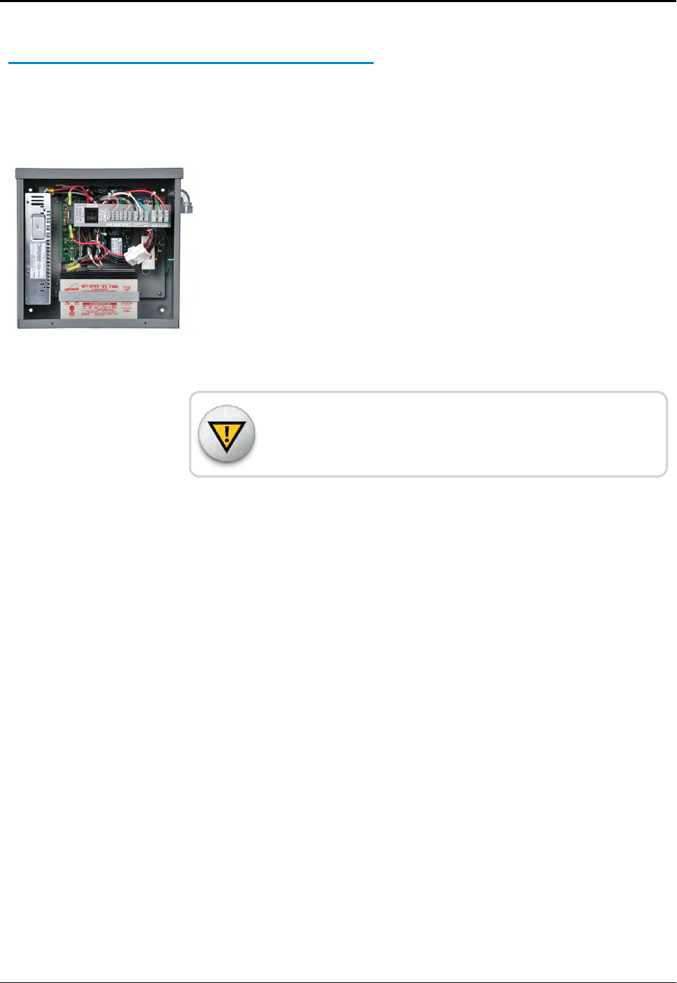
Figure 35 – Outdoor UPS (Closed) 37
Figure 36 – Outdoor UPS (Cover Removed) 37
Figure 37 – Strut Channel or Wall Mounting 44
Figure 38 – Pole Mounting Straps 44
Figure 39 – Wire Input and Output Connectors 46
Figure 40 – RMDC Power Plug 47
Figure 41 – LEDs Above CPU 54
Figure 42 – Ethernet Status LEDs 55
Figure 43 – Radio LEDs 55
Figure 44 – Modem Indicator LEDs 56
Figure 45 – Radio Modem Power Front Panel Connector 57
Figure 46 – RMDC Power Supply 58
Figure 47 – Radio Modem Power Front Panel Connector 58
Figure 48 – Vanguard Modem Power Connector 59
Figure 49 – CalAmp Vanguard Modem with RSSI LED 59
Figure 50 – NTG Modem Status LEDs 60
Figure 51 – Standoff Mounting Bracket 80
Figure 52 – RF 450 MHz Antenna 80
Figure 53 – RF 450 MHz Antenna to be Mounted 82
Figure 54 – Securing the Pole Bracket 82
Figure 55 – Lining Up Second Bracket 83
Figure 56 – RF 450 MHz Antenna Connection 83
Figure 57 – Weatherizing the RF Antenna Connection 84
xiv R450™Rack Mount Data Collector Installation and Maintenance Guide
Figures

R450™Rack Mount Data Collector Installation and Maintenance Guide xv
Figure 58 – Collector Search 87
Figure 59 – Collector Search Results 88
Figure 60 – Create a New Collector Window 89
Figure 61 – Collector Network Setting Tab 91
Figure 62 – Delete Confirmation Dialog Box 92
Figure 63 – Save USB Build 93
Figure 64 – Thumb Drive Created 93
Figure 65 – Straight-Through Ethernet Cable 95
Figure 66 – RJ-45 Crossover Ethernet Cable 95
Figures

This page intentionally left blank.
xvi R450™Rack Mount Data Collector Installation and Maintenance Guide
Figures

Tables
Table 1 – R450™ RMDC Cellular Modem Components List (P/N 12799-800) 8
Table 2 – R450™ RMDC Ethernet Components List 9
Table 3 – Electrical Specifications 11
Table 4 – Environmental Conditions 11
Table 5 – Recommended Tools and Materials 13
Table 6 – R450 RMDC Pole Mounting Hardware Recommendations 16
Table 7 – Installing a Wall Mount System 23
Table 8 – R450 RMDC Wall Mounting Hardware Recommendations 24
Table 9 – Lights on the CPU Board 33
Table 10 – Radio Tx Light - Identify Problem 35
Table 11 – UPS Specifications 38
Table 12 – Input Specifications 38
Table 13 – Output Specifications 38
Table 14 – Battery Specifications 39
Table 15 – Physical Specifications 39
Table 16 – Safety Specifications 39
Table 17 – Environmental Specifications 39
Table 18 – UPS Safety Checklist 40
Table 19 – Battery Safety Checklist 41
Table 20 – RMDC Does not Power Up 48
Table 21 – UPS Status LEDs 48
Table 22 – Verify UPS is Producing Correct Voltage 49
Table 23 – Visual Check Modem RSSI and SVC LEDs 56
Table 24 – Modem Status LEDs 57
Table 25 – Material Needed for Cable Installation 68
Table 26 – Neptune Part Numbers for Cable 69
Table 27 – Connectors and Accessories 69
Table 28 – Antenna Specifications 70
R450™Rack Mount Data Collector Installation and Maintenance Guide xvii

Table 29 – Power Measurement to Return Loss and VSWR Conversion Table -Part I 72
Table 30 – Power Measurement to Return Loss and VSWR Conversion Table -Part II 73
Table 31 – Coax Cable Loss Table 75
Table 32 – Recommended Tools and Materials 80
Table 33 – Collector Details 90
Table 34 – Collector Network Settings 91
Table 35 – Cable Color Code Table 96
Table 36 – Coax Cable Recommendations for Cellular Antenna 97
Table 37 – Recommended Stainless Steel Strut Clamps 99
xviii R450™Rack Mount Data Collector Installation and Maintenance Guide
Tables
R450™Rack Mount Data Collector Installation and Maintenance Guide 1
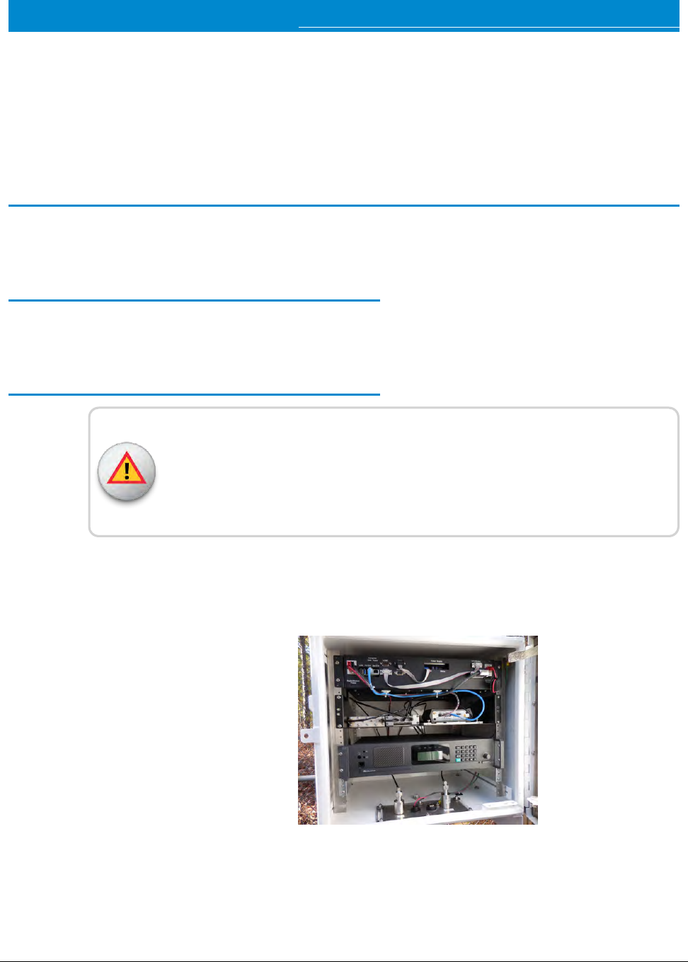
Chapter 1: Product Description
This chapter introduces the installation process. It explains the focus of the guide,
the pre-installation personnel responsibilities, and general information on technical
support.
General Product Overview
This section provides a general description of the R450™ Rack Mount Data
Collector (RMDC).
The RMDC receives, stores, and communicates meter reading data to the Neptune
host software. The RMDC collects meter reading data from Neptune’s R450™ Meter
Interface Unit (MIU) interfacing with Neptune’s absolute encoder register. This data
can be uploaded to the Customer Information System (CIS) and sent to the utility
billing system for processing.
Figure 1 – R450™ Rack Mount Data Collector
The RMDC operates in frequencies in the 450-470 MHz
licensed band. A Federal Communications Commission (FCC)
license is required prior to installation of the system.
Before you Begin
Before you install the RMDC, it is important to become familiar with
the unit and its components. This guide is intended for installer
and is designed to help in the installation process. It contains
information on the components and specifications, the site
selection, and the actual installation of the unit.
WARNING: If the installation site requires digging, survey the
area for concealed hazards. Call 811, the Call Before You Dig
phone center, before proceeding. Be sure to locate any electric,
natural gas, and water lines as well as cable and phone lines. In
some states and jurisdictions, it is the law. Most state laws
require at least two to three full work day's notice. Install in
accordance with the FCC site license.
Two Versions of RMDC Installation
There are two RMDC versions available depending on the utility's
backhaul preference. Each type is powered by external 12V DC
power. Power is supplied to the RMDC by an Uninterruptible
Power Supply (UPS).
Neptune provides an installation kit for each type of installation.
The standard configuration of the RMDC backhaul is a cellular
modem. The other backhaul option available is an Ethernet
connection.
Backhaul Type
lCellular modem (P/N 12799-800)
lEthernet (P/N 12799-810)
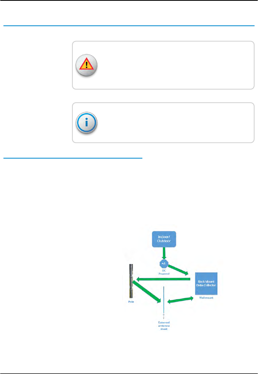
The RMDC can be mounted on a wall, a pole, or H-frame.
2 R450™Rack Mount Data Collector Installation and Maintenance Guide
Chapter 1: Product Description
Determining How to Install the RMDC
Consider the following information.
WARNING: Do not mount the RMDC, antenna mast, antenna, or
lead-in conductor to a pole or similar structure carrying open
electric light, power wires, or trolley wires over 250 volts. See
NEC, Article 810.
Depending upon the availability of communications, you can
use a cellular modem or Ethernet backhaul. Use with the
selection checklist before installing the RMDC.
Mounting Components
This section describes the various mounting components for the
RMDC.
Wall Mount
A wall-mounted RMDC can be installed indoors; however, because
the unit uses an external antenna, you need an antenna mast.
Refer to Figure 2 for how to mount the RMDC to a wall.
Figure 2 – Wall-Mount Installation
R450™Rack Mount Data Collector Installation and Maintenance Guide 3
Chapter 1: Product Description
Depending upon the availability of communications, you can
use a cellular modem or Ethernet backhaul.
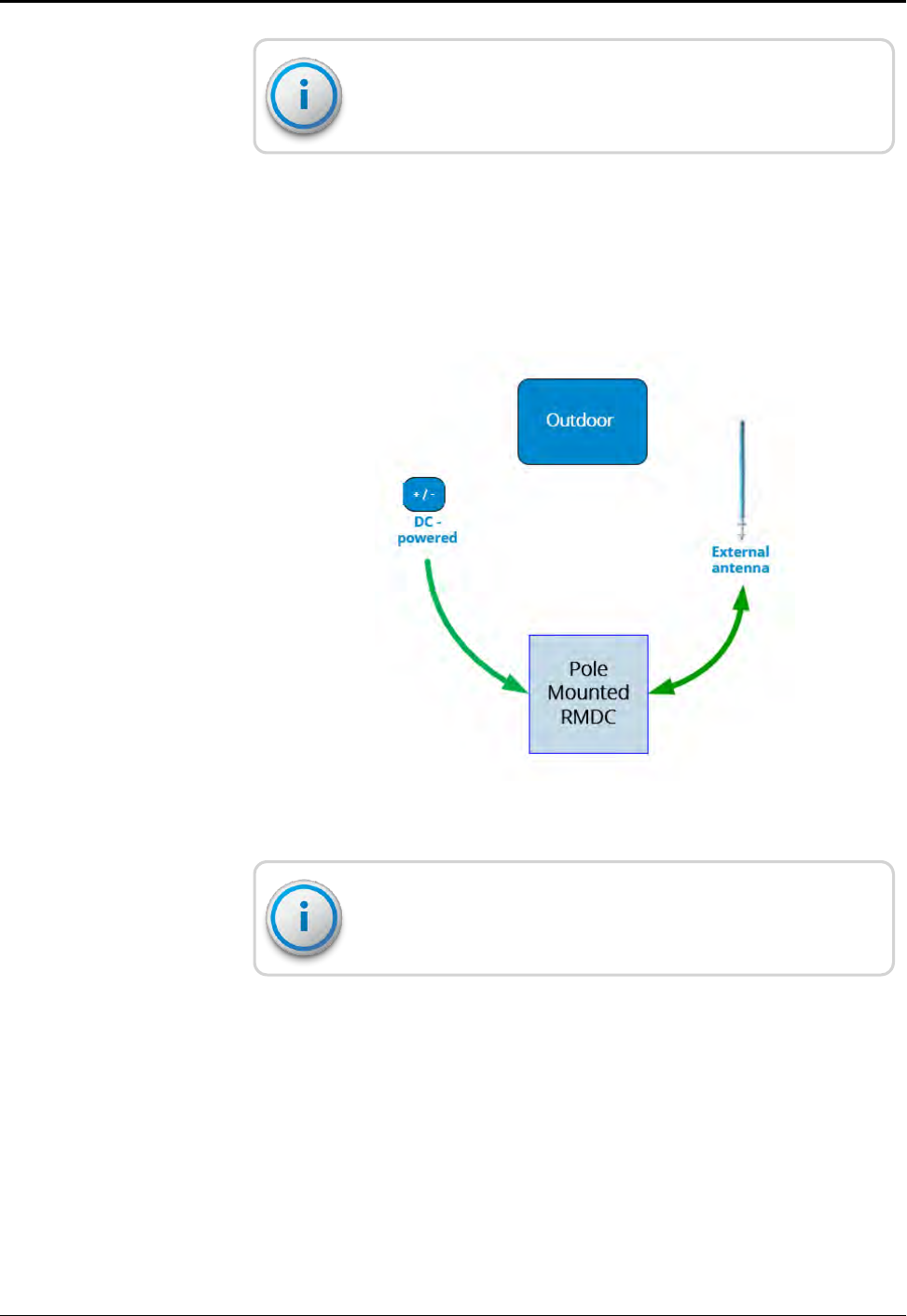
Poleor H-Frame Installation
Use the pole or H-Frame installation to mount the R450 RMDC on
an outdoor free-standing pole or H-frame. Refer to Figure 3 for
how to install the RMDC on a pole.
Figure 3 – Pole Installation
Depending upon the availability of communications, you can
use a cellular modem or Ethernet backhaul.
4 R450™Rack Mount Data Collector Installation and Maintenance Guide
Chapter 1: Product Description
Optimizing System Performance
This section addresses situations where the system is functioning,
but the R450 RMDC or MIU communication is not performing as
expected.
This discussion covers two situations:
lNewly-installed system does not perform per specification.
lInstalled system performance degrades suddenly or over time.
Optimizing the Performance of a New System
Before you install the system, Neptune uses computer software
and other resources to predict the performance of the system.
Each site survey recommends a minimum number of RMDCs to
provide the desired performance over a specified coverage area.
The survey also recommends antenna placement and looks for
potential radio interference. Neptune provides a propagation
model which uses sophisticated software to predict the system
performance. If you place an RMDC outside the recommended
locations, it might not perform well.
CAUTION: If Neptune's propagation model is not followed,
inadequate performance can occur.
Proper Operation
Review the following note.
Owners of both licensed and unlicensed equipment are
responsible for the proper operation of their equipment. If it is
not operating within specifications, the owner is required to
bring the system into compliance or stop using it. The
collaborative effort of all the affected parties is required to solve
this problem.
It is possible for a piece of equipment to be functioning totally
within its required specifications and still cause interference with
the R450™ System.
R450™Rack Mount Data Collector Installation and Maintenance Guide 5
Chapter 1: Product Description
During the initial installation, Neptune advises using a receiver or
high-quality spectrum analyzer connected to the antenna to assure
the transmit and receive frequencies are free from interference.
Additionally, be sure that there are no potentially interfering signals
around the frequencies the RMDC uses for transmitting and
receiving. The overall noise level can potentially reduce the
sensitivity of the RMDC or MIU receivers. A Rohde & Schwarz
FSH3.03 or FSH3.23 or equivalent spectrum analyzer is
acceptable.
Problems can occur from a number of sources. Some common
problems include:
lImproper installation resulting in loose connectors. Refer to "RF
Antenna Installation" on page65 of Appendix A to confirm the
correct installation procedures.
CAUTION: You must provide Appendix A to antenna contractors
prior to installation. Failure to follow the procedures in the
Appendix can result in poor system performance.
lLocal cable systems operating with RF leakage from cables and
amplifiers can degrade the performance of the R450 System.
lLocal businesses and factories can have equipment that raises
the ambient noise level, reducing the ability of the RMDC to hear
MIUs.
lLocal residences and businesses can have equipment that
interferes with the R450 System.
Site surveys often find these problems but cannot detect
intermittent, factory shift-related, or other time-specific sources of
interference.
Being in close proximity to a high-power commercial broadcast
antenna produces a unique set of problems. Loose or badly
corroded hardware on or near the site can cause signals from the
RMDC or other transmitters near the site to combine with the
broadcast signal and produce interfering signals. Incorrectly
installed antennas and feed lines can also cause similar problems.
The RMDC and other local transmitters themselves can also be a
source of re-radiated interference. Additional equipment that your
installer recommends can help control these issues.
6 R450™Rack Mount Data Collector Installation and Maintenance Guide
Chapter 1: Product Description

Terrain and the types of buildings in the area can affect the
performance of the R450 System. Hilly or rolling terrain as well as
tall buildings can make it difficult to receive even local MIU data.
Placement of the MIUs (wall mount and pit style) can be critical in
some areas. Additional RMDCs that supplement the problem areas
is the best solution in these situations.
Maintaining the Performance of the R450 System
For consistent performance, be sure that you have properly
installed all the R450 MIUs so that the R450 System can reliably
receive their transmissions.
The Troubleshooting chapter of this guide includes
recommendations on how to verify that the RMDC and antenna
system are performing up to specification.
Storm activity can degrade the performance of the RMDC. If this
happens, check the lightning arrestors and replace them, if
defective.
Running the surveys again using the radio receiver can identify new
sources of interference. For problems related to specific time
periods, run the surveys during those time periods.
RMDC Components
The following section describes the components of the RMDC.
Cellular Modem
The RMDC is mounted on either a pole, wall, or H-Frame. Table 1
on the next page includes the components for the RMDC cellular
modem version.
R450™Rack Mount Data Collector Installation and Maintenance Guide 7
Chapter 1: Product Description
Part Number Description Qty
12799-800 R450 Rack Mount, 4G Cellular Modem includes:
lUninterruptible power supply (UPS)
l4G/LTE cellular antenna
l6-foot cellular coax cable
lStrut clamp
lRJ45 connector,
lEnclosure key
lManual
1
12896-001 Antenna, RF Omni (mounting hardware included) 1
Coax cable (see Appendix A, "RF Antenna Installation" on page65) As required
13751-001 Antenna, 4G LTE cellular (included with the RMDC) 1
10046-112 Coax Cable, six-foot, cellular antenna (included with the RMDC) 1
13750-001 Strut clamp, 3/4-inch, stainless steel (included with RMDC) 1
13450-200 Uninterruptible Power Supply (UPS)kit (includes UPS, pole/wall mounting
bracket, DC power cord, DC cord grip, and stainless steel clamps). Other
vendors supply wall mounting hardware.
1
12835-002 RMDC Installation and Maintenance Guide 1
Table 1 – R450™ RMDC Cellular Modem Components List (P/N 12799-800)
The cellular modem requires a System Information Manager
(SIM) card which must be ordered separately. To obtain a SIM
card, contact your preferred cellular service provider and give
them the modem Mobile Equipment Identifier (MEID)
andInternational Mobile Equipment Identifier (IMEI) numbers.
8 R450™Rack Mount Data Collector Installation and Maintenance Guide
Chapter 1: Product Description

Ethernet
Table 2 shows the parts included in the RMDC Ethernet kit.
Part Number Description Qty
12799-810 R450 Rack Mount, Ethernet version includes:
lUninterruptible power supply (UPS)
l4G/LTE cellular antenna
l6-foot cellular coax cable
lStrut clamp
lRJ45 connector
lEnclosure key
lManual
1
12896-001 Antenna, RFOmni (mounting hardware included) 1
Coaxial cable (see Appendix A, "RF Antenna Installation" on page65 As required
13450-200 UPS Kit (includes UPS, pole/wall mounting bracket, DC power cord, DC cord
grip, and stainless steel clamps). Wall mounting hardware to be supplied by
others
1
13138-001 External RJ45 Plug Kit (included with R450 RMDC - Ethernet version) 1
12835-002 RMDC Installation and Maintenance Guide 1
Table 2 – R450™ RMDC Ethernet Components List
R450™Rack Mount Data Collector Installation and Maintenance Guide 9
Chapter 1: Product Description

This page intentionally left blank.
Chapter 1: Product Description
10 R450™Rack Mount Data Collector Installation and Maintenance Guide
R450™Rack Mount Data Collector Installation and Maintenance Guide 11
Chapter 2: General Installation Guidelines
This chapter describes the specifications for the R450™ Rack Mount Data Collector
( RMDC). It includes information on storage, unpacking, preliminary tests, tools,
materials, site selection, and installation of the RMDC.
RMDC Specifications
This section provides the specifications of the RMDC.
Electrical Specifications
Specification Description
DCPower 12V DC, 7A
Power Consumption 84 Watts
Table 3 – Electrical Specifications
Environmental Conditions
Condition Description
Operating Temperature -22° to 140°F (-30° to 60°C)
Storage Temperature -40° to 185°F (-40° to 85°C)
Operating Humidity 0 to 95% Non-condensing
Environmental Rating NEMA 4X enclosure box
Operating Altitude Less than 6561 feet (2000 meters)
Table 4 – Environmental Conditions
Mechanical Specifications
The weight of the RMDC is 100 lbs.
RMDCFootprint
The RMDC measures 24"h x 27"w x 23"d.
Storage
Upon receipt, inspect shipping containers and their contents for damage prior to
storage.
After inspection, store the cartons in a clean, dry environment where the
temperature remains between -40° and 185°F (-40° and 85°C).
Unpacking
As with all precision electronic instruments, handle the RMDC with
care; however, no special handling is required.
After unpacking the RMDC, inspect it for damage. If any parts of the
RMDC appear to be damaged or prove to be defective upon
installation, notify your Neptune sales representative. If the unit or
item requires reshipment, use the original cardboard box and
packing material.
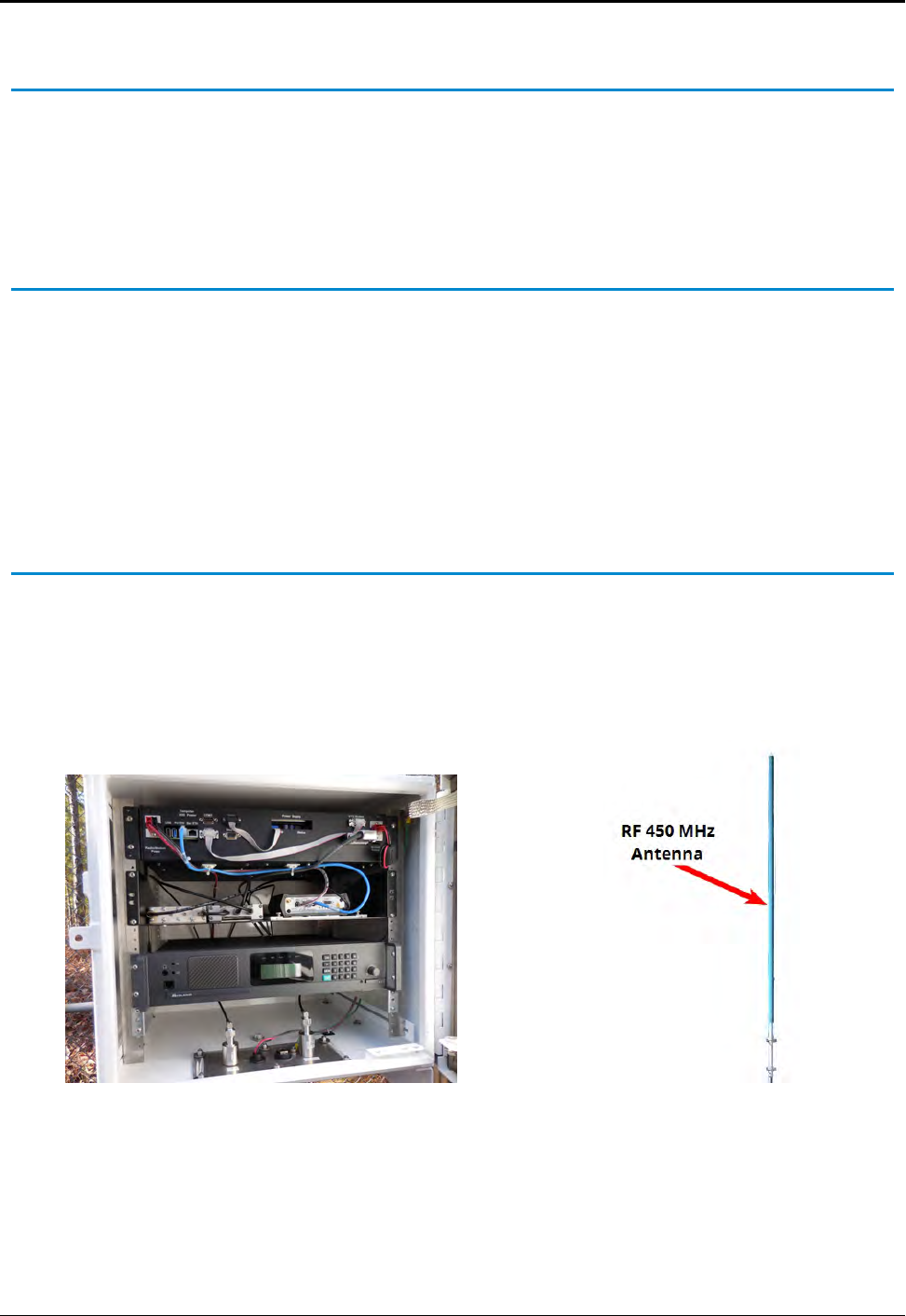
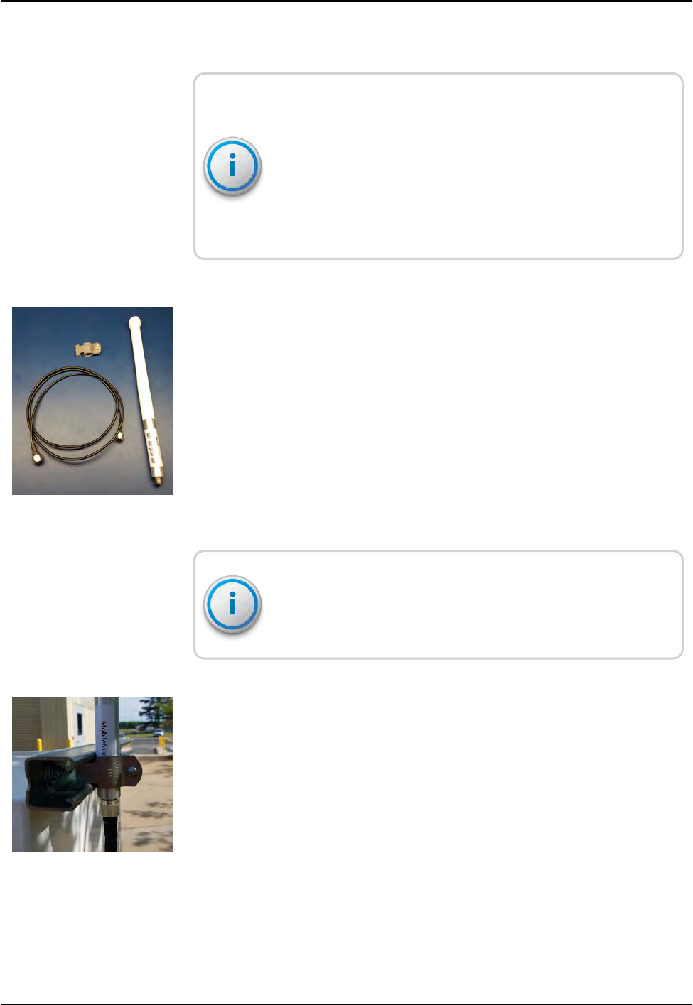
RMDC Installation Kits
The RF 450 MHz antenna and accessories are now ordered
separately from the RMDC. The RF 450 MHz antenna, coaxial
cables, and coaxial connectors must be ordered as accessories.
See "RF Antenna Installation" in Appendix A for a list of the antenna
accessories and cables.
Figure 4 – R450 Rack Mount Data Collector Figure 5 – RF 450 MHz Antenna
12 R450™Rack Mount Data Collector Installation and Maintenance Guide
Chapter 2: General Installation Guidelines
Tools and Materials
Table 5 below shows the recommended tools and materials you
need to successfully install the RMDC.
Some items do not apply to your specific installation, and the list
does not contain all tools or materials depending on which
installation method you use.
Item Description/Recommendation Use
Tool Kit Contains standard tools including:
lAssorted screwdrivers (medium, Flat-
Head (slotted), Phillips head)
lCordless electric drill/assorted bits
lAdjustable wrench
lStandard socket wrench set
lStandard box-end wrench set
lHammer
lChannel locks
Various installation procedures
performed by the installer.
UV-Stable Ties 8" and 12" (20.32 cm and 30.48 cm) Securing smaller short coaxial.
Cable Hangers Various sizes Securing coaxial cable. For larger
coaxial (1/2" diameter and larger),
secure to tower or structure per
manufacturers recommendations.
RMDC Key Key for lock on unit Securing the unit.
Weatherizing Kit 3M Scotch®Wireless Kit P/N: WK-101 or
Times Microwave P/N: WK-S-2
Weatherproofing coaxial cable
connections.
Coaxial Grounding Kit SG12-06B2A for 1/2" LDF4-50 Coaxial or
SG78-06B2A for 7/8" AVA5-50 Coax
Grounding coaxial cable (see
Andrew Bulletin 17800B-JC).
Coaxial Hoisting
Grips
As recommended by coaxial cable
manufacturer (see Andrew Bulletin
17800B-JC)
For tower and monopole
installations - hoist and secure
coaxial
Personal Protective
Equipment (PPE)
Wear OSHA approved PPE as required.
Safety glasses must meet ANSI Z87.1
Table 5 – Recommended Tools and Materials
R450™Rack Mount Data Collector Installation and Maintenance Guide 13
Chapter 2: General Installation Guidelines

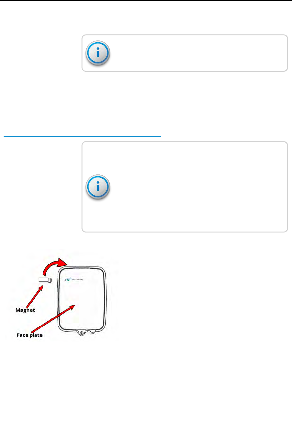
R450 MIU and Magnet
If you have R450 MIUs already installed, you can use these to test if
the RMDC is receiving readings. However, it is recommended that
you take an R450 MIU and Neptune magnet with you when you
install the RMDC. These items are needed to test the unit. See
"Swiping the MIU" on page34.
When you install the R450 MIU, be sure that the N_SIGHT PLUS
host software is running and that you have an R450 MIU and
magnet with you. Use the R450 MIU and magnet to test the
unit.
14 R450™Rack Mount Data Collector Installation and Maintenance Guide
Chapter 2: General Installation Guidelines
R450™Rack Mount Data Collector Installation and Maintenance Guide 15
Chapter 3: Installing theR450™RMDC
This chapter details the installation instructions for the R450™ Rack Mount Data
Collector (RMDC). There are two installation options:
l"Mounting the RMDC to a Pole or H-Frame" below
l"Installing theR450™RMDC " above
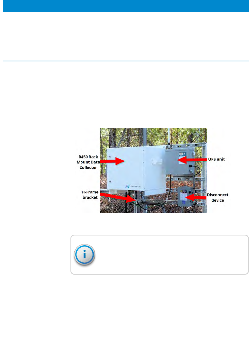
Mounting the RMDC to a Pole or H-Frame
This section provides information on mounting the RMDC to a pole or
H-frame.
Locating the Site
Choose a location that does not interfere with any other wiring and is easily
accessible. After selecting a site, complete the following procedures.
Mounting Recommendations
WARNING: Outdoor antennas and coaxial cables should maintain a clearance of
at least 2 feet (0.6 m) from open electric light or power service conductors of 250
volts or less. If the power wires are more than 250V, maintain a clearance of at
least 10 feet (3.0 m) per NEC Article 810 and CEC Section 54.
You can mount the RMDC to a pole (4 inch or larger) using two 3/4-inch wide
stainless steel straps (Band-It #C20699 strap, #C25699 buckle, and #C00169
standard tool). Other vendors supply the straps, buckles, and standard tools.
Hardware needs to be corrosion resistant and coastal areas can use stainless steel.
Figure 6 – R450 Rack Mount Data Collector
Mounting Hardware Recommendations
Table 6 lists installation types and the recommended mounting
hardware to use.
Installation Type Comments Recommended Mounting Hardware
(supplied by other vendors)
Small Pole 2-inch to 4-inch diameter galvanized
steel, Schedule 40
lSlotted or half slot steel strut channel (1-5/8" x 1-
5/8" x 22" L), two mounted to the back of the R450
RMDC enclosure
l3/8"-16 x 1" Grade 8 (A490) bolts, four minimum1
l3/8"-16 nuts
l3/8" fender washers
lTwo steel strut clamps (2" to 4" depending on pole
size)
lOptional: 1/4"-20 x 1" Grade 8 (A490) bolts; use a
minimum of eight; also, 1/4"-20 nuts and 1/4"
fender washers
Large Pole 4-inch diameter or larger Use two 3/4" wide stainless-steel straps (Band-It
#C20699 strap, #C25699 buckle, and #C00169
standard tool)
2-Pole
"H-Frame" Strut
Channel
Recommended minimum pole size is
2-inch diameter galvanized steel,
Schedule 40
3/8"-16 x 1" bolts, 3/8"-16 spring nuts, and 3/8"
washers; use a minimum of four 3/8" bolts
Optional: 1/4"-20 x 1" Grade 8 (A490) bolts and 1/4"
washers; use a minimum of eight
1Note: If mounting to the shallower 13/16" depth strut channel (1-5/8" x 13/16"), then 7/8" long bolts are recommended to keep from
bottoming out.
2Note: Hardware listed is the minimum allowable recommended hardware. Additional provisions can be necessary for high wind areas.
Table 6 – R450 RMDC Pole Mounting Hardware Recommendations
For pipe mounting, use Schedule 40 or Schedule 80 galvanized
steel pipe with at least a 2-inch or larger diameter. Seat the pipe
per local codes.
16 R450™Rack Mount Data Collector Installation and Maintenance Guide
Chapter 3: Installing theR450™RMDC
For general recommendations on strut clamps and sizing
information, see Appendix E: " Strut Clamp Recommendations"
on page99.
Attaching Cables for the RMDC
The corresponding sections detail how to attach the following
components:
lRF 450 MHz antenna cable
lGround wire
lCellular antenna
lAC Power plug
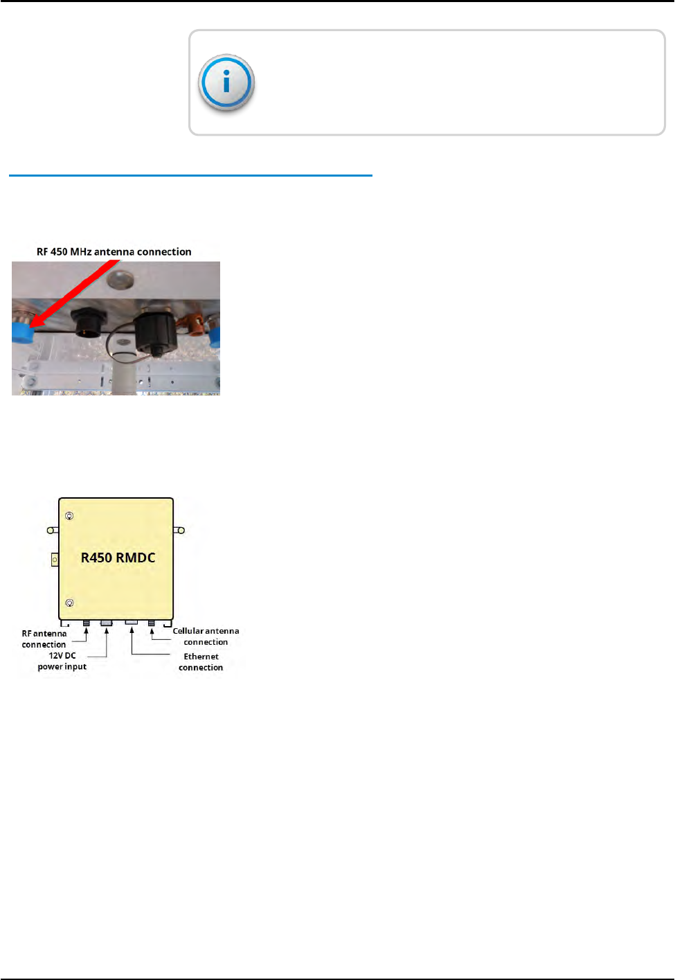
Figure 7 – RF 450 MHz Antenna Connection
Attaching the RF 450 MHz Antenna Cable
To attach the RF 450 MHz antenna cable, complete the following
steps.
1. Locate the RF 450 MHz antenna cable that extends from the
RF 450 MHz antenna cable conduit.
2. Connect the RF 450 MHz antenna cable to the RF 450 MHz
antenna connector located on the bottom of the RMDC. See
Figure 8
3. Tighten the coaxial connector to 15 - 20 in-lb (1.7 - 2.2 Nm)
for N-type connector.
Figure 8 – Antenna Connections
R450™Rack Mount Data Collector Installation and Maintenance Guide 17
Chapter 3: Installing theR450™RMDC
WARNING: Give special consideration when the RMDC you
installed is inside a building.
Connect the outer conductor (shield) of the coaxial cable to the
earth (grounded) at the entrance to the building using the
appropriate coax grounding kit. Be sure this is done in
accordance with applicable national electrical installation codes
(Section 820.93 of the National Electrical Code (NEC),
ANSI/NFPA 70).
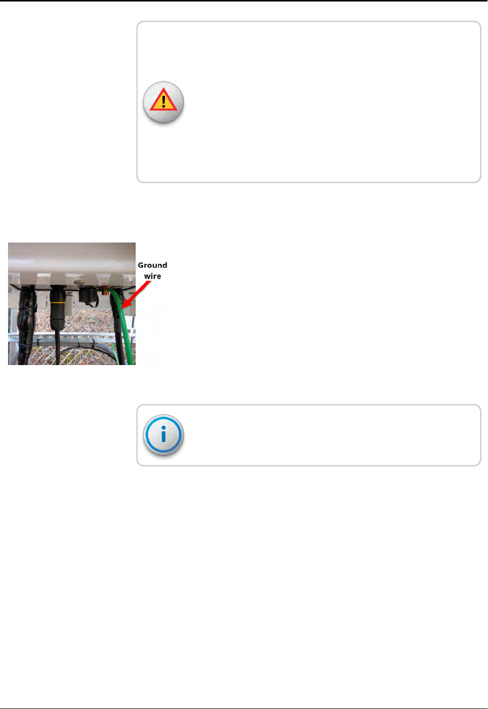
Connecting the Ground Wire
To attach the ground wire, complete the following steps.
1. Locate the lightning protection system ground for the site.
2. Connect the external ground lug of the RMDC to the lightning
protection system ground for that site, as illustrated in Figure
9. Use #6 American Wire Gauge (AWG) copper wire with a
minimum temperature rating of 75°C.
3. Tighten with a flathead screwdriver. Torque to 35 in-lb. (4.0
Nm).
Figure 9 – Ground Wire
If you are using an Ethernet backhaul, see"Connecting the
Ethernet Cable" on page26.
18 R450™Rack Mount Data Collector Installation and Maintenance Guide
Chapter 3: Installing theR450™RMDC
Mounting the Cellular Antenna
Neptune recommends mounting the cellular antenna to the
tower or mast. Make sure the tower (or mast) does not obscure
the line of sight path to the nearest cellular carrier's tower.
If the cellular modem RSSI signal level is marginal or weak,
relocate the cellular antenna to the opposite side of the tower
(or mast).
To mount the cellular antenna, complete the following steps.
1. Locate the cellular antenna, and strut clamp. See Figure 10.
Figure 10 – Items for Cellular Antenna
Some installations require a longer coax cable for the cellular
antenna connection. See "Appendix D: Cellular Antenna Coax
Cable" for recommendations.
2. Using the 3/4-inch strut clamp, attach the cellular antenna to
one side of the top strut channel connected to the back of the
RMDC, as illustrated in Figure 11.
Figure 11 – Attaching the Cellular Antenna
R450™Rack Mount Data Collector Installation and Maintenance Guide 19
Chapter 3: Installing theR450™RMDC
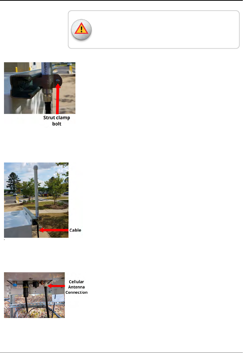
WARNING: Secure the clamp around the silver band of the
cellular antenna only. Damage can occur if the clamp is secured
around any other part of the antenna.
3. Using a 3/8-inch socket wrench, tighten the bolt for the strut
clamp around the cellular antenna, as illustrated in Figure 12.
Figure 12 – Tighten Bolt for Cellular Antenna
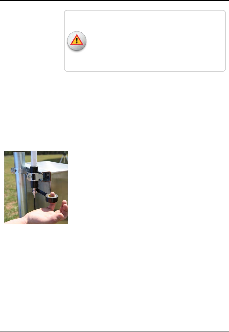
4. Connect the cable to the cellular antenna before connecting it
to the base of the RMDC. See Figure 13.
5. Tighten the coaxial cable connection to 14 in-lb.
(1.58 Nm).
Figure 13 – Cable to Cellular Antenna
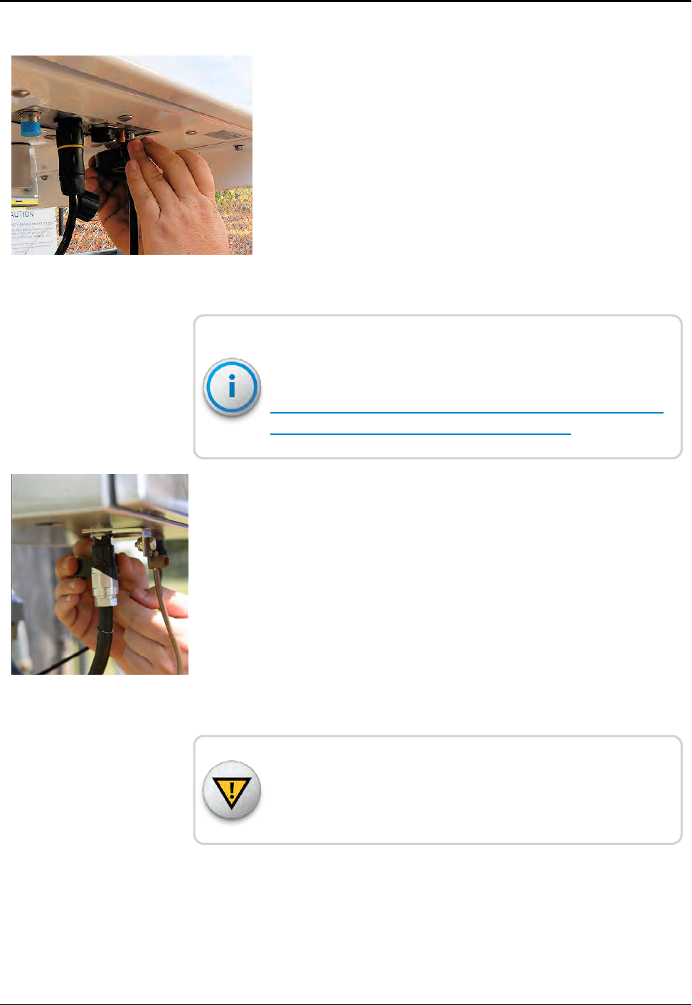
6. Connect the cellular antenna cable to the base of the
RMDC. See Figure 14.
7. Tighten to 14 in-lb. (1.58 Nm).
Figure 14 – Cellular Antenna Connection at Base
20 R450™Rack Mount Data Collector Installation and Maintenance Guide
Chapter 3: Installing theR450™RMDC
WARNING: Give special consideration when the
RMDC is installed inside a building.
The screen (shield) of the coaxial cable must be connected to
earth (grounded) at the entrance to the building. Do this in
accordance with applicable national electrical installation codes
(Section 820.93 of the NEC, ANSI/NFPA 70).
Attaching the Power Plug to the RMDC
Attach the circular power plug to the bottom of the RMDC. Push
the connector plug upward while rotating the outer sleeve
clockwise until you feel engagement.
Weatherizing the Cable Connections
Complete the following instructions to weatherproof the cables
using the 3M Scotch®Wireless WK-101 or an equivalent
weatherproofing kit.
1. Using the weatherizing kit, start the tape at the bottom of the
cellular antenna connection as illustrated in Figure 15.
2. Wrap the tape around the connection several times; slowly
work your way up to weatherize your connection at the base.
3. Wrap the 3M Butyl Mastic Tape 2212 according to the
detailed installation instructions in the
3M Scotch®Wireless Weatherproofing kit.
Figure 15 – Weatherizing Connections
4. Wrap the entire section of cable with one or two layers of half-
lapped 2-inch (51 mm) wide Scotch®Super 33+™ Vinyl
Electrical Tape according to the detailed installation instructions
in the 3M Scotch®Wireless Weatherproofing kit.
R450™Rack Mount Data Collector Installation and Maintenance Guide 21
Chapter 3: Installing theR450™RMDC
5. Repeat steps 1 and 2 to weatherize the cellular connection at
the base of the RMDC, as illustrated in Figure 16.
Figure 16 – Weatherizing the BaseConnection
For detailed installation instructions on the 3M Scotch®
Wireless Weatherproofing Kit (P/N: WK-101) refer to:
http://multimedia.3m.com/mws/media/659028O/scotc
h-wireless-weatherproofing-kit-wk-101.pdf.
6. Repeat steps 1 through 4 to weatherize the RF 450 MHz
Antenna feed-in connection at the base of the RMDC, as
illustrated in Figure 17.
Figure 17 – Weatherizing the AntennaConnection
CAUTION: Wiring the AC-power for the UPS must be done by a
licensed electrician. Install the wiring in accordance with the NEC,
Canadian Electrical Code (CEC), and local electrical codes.
22 R450™Rack Mount Data Collector Installation and Maintenance Guide
Chapter 3: Installing theR450™RMDC
Installing a Wall Mount System
The following section contains the instructions needed to install a
wall mount system.
Complete Instructions Cellular Ethernet
1 "Installing theR450™RMDC " on page
15
2 "Installing theR450™RMDC " on page
15
3 "Mounting the Cellular Antenna" on
page19
4 "Connecting the Ethernet Cable" on
page26
5 "Installing theR450™RMDC " on page
15
Table 7 – Installing a Wall Mount System
Mounting the RMDC to a Wall
Choose a location that does not interfere with any other wiring
and is easily accessible.
Mounting hardware (screws, bolts, slotted or half-slot steel strut
channels, spring nuts, and strut clamps) for wall or strut channel
installations, are provided by the party responsible for the
installation. Hardware needs to be corrosion resistant and coastal
areas can use stainless steel.
To mount the RMDC to a wall as illustrated in Figure 18 on page
24, use the following mounting hardware recommendations
shown in Table 8 on the next page.
R450™Rack Mount Data Collector Installation and Maintenance Guide 23
Chapter 3: Installing theR450™RMDC
Figure 18 – RMDC Mounted on Wall
The mounting hardware listed in Table 8 is supplied by other
vendors and should be corrosion resistant. Coastal areas can
use stainless steel.
Installation Type Comments Recommended Mounting Hardware
(supplied by installation vendors)
Wall - strut
channel
Mounting the RMDC to the strut channel that
is mounted to the wall
Use the following:
lTwo pieces of slotted or half-slot steel
strut channel (1-5/8" x 1-5/8" x 22" L)
l3/8"-16 x 1" Grade 8 (A490) bolts
l3/8"-16 spring nuts
l3/8" washers
lUse minimum of four 3/8" bolts.
Optional:
l1/4"-20 x 1" Grade 8 (A490) bolts
l1/4" washers; use a minimum of eight
Table 8 – R450 RMDC Wall Mounting Hardware Recommendations
24 R450™Rack Mount Data Collector Installation and Maintenance Guide
Chapter 3: Installing theR450™RMDC
Installation Type Comments Recommended Mounting Hardware
(supplied by installation vendors)
Wall - direct Mounting RMDC directly to wall Use the following:
l1/4" x 1-3/4" wood screws or
l1/4" x 1-3/4" masonry screws(for
example Tapcon HW4-134)
lUse a minimum of eight screws
Table 8 – R450 RMDC Wall Mounting Hardware Recommendations (continued)
Connecting Antenna Cables to the RMDC
The RF 450 MHz antenna and the communications antenna
connect on the outside of the building to the RMDC inside the
building.
1. Locate an area behind the wall where the cables can thread
through to the outside of the building.
2. Secure the cables to the bottom of the RMDC as illustrated in
Figure 19.
3. Thread the cables through to the RMDC antenna and mast.
4. Continue to work with the cables on the outside of the
building.
Figure 19 – Adding Cables to the RMDC
Mounting the Cellular Antenna
See "Mounting the Cellular Antenna" on page19
If you are using an Ethernet backhaul, refer to "Connecting the
Ethernet Cable" on the next page.
R450™Rack Mount Data Collector Installation and Maintenance Guide 25
Chapter 3: Installing theR450™RMDC
Mounting Hardware
When mounting hardware, consider the following.
Mount the antenna using a unistrut for the collector or on
separate mounting hardware. The bracket (P/N: 13750-001) is
needed with the cellular kit variant of the R450 RMDC (P/N:
12799-800).
Connecting the Ethernet Cable
This procedure is only for kits using the Ethernet backhaul
connection. If you are using a cellular modem and antenna,
refer to "Mounting the Cellular Antenna" on page19.
Prior to connecting to the Ethernet port (10/100/1000 Mbps) of
the RMDC, you must run an Ethernet cable to the location of the
RMDC. If you installed an Ethernet cable outside, be sure it is
shielded and outdoor rated CAT5E or CAT5. For example, a Belden
cable (P/N 7919A).
To connect to the Ethernet Port (10/100/1000 Mbps), complete
the following steps.
1. Locate the Ethernet port (10/100/1000 Mbps) at the bottom
of the RMDC. See Figure 20. Refer to Appendix C "Ethernet
Termination" on page95for more information.
Figure 20 – Ethernet Port Connection
26 R450™Rack Mount Data Collector Installation and Maintenance Guide
Chapter 3: Installing theR450™RMDC
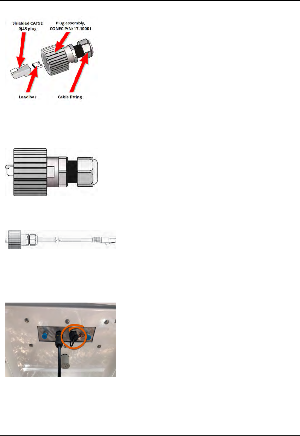
2. Locate the Ethernet plug that is included with the
RMDC. See Figure 21.
Figure 21 – Feed-Through Assembly
3. Assemble the Ethernet plug according to the instructions
included. See Figure 22.
Figure 22 – RJ45 Ethernet Plug
4. Terminate the Ethernet jack to the Ethernet cable. See
Figure 23. Refer to Appendix C "Ethernet Termination" on
page95
Figure 23 – Ethernet Plug Terminated
5. Insert the Ethernet plug into the Ethernet receptacle on the
RMDC. See Figure 24.
6. Screw the entire Ethernet plug assembly into the RJ45
Ethernet housing, which is already mounted at the bottom
of the RMDC.
7. Tighten the cable fitting until the gasket is tight around the
RJ45 cable.
Figure 24 – Ethernet Plug Receptacle
R450™Rack Mount Data Collector Installation and Maintenance Guide 27
Chapter 3: Installing theR450™RMDC
The Ethernet connector is weatherproof (IP67 rated) and does
not require weatherproofing wrap.
When the Ethernet port is not in use, cover it with the protective
guard (CONEC P/N:17-10002).
Connecting the Cables to the RMDC
Connect the cables to the RMDC by completing the following
steps.
1. Locate where the cables connect on the bottom of the
RMDC.
2. Secure the cables to the bottom of the RMDC as illustrated in
Figure 25.
Figure 25 – Connecting the RMDC
3. Thread the cables through to the RF 450 MHz Antenna.
4. Wire the DC-power as described in "Installing theR450™RMDC
" on page15.
5. Weatherproof all coax cables using the weatherizing kit.
6. Verify all the connections as described in "Testing the
Connections" on page33.
28 R450™Rack Mount Data Collector Installation and Maintenance Guide
Chapter 3: Installing theR450™RMDC
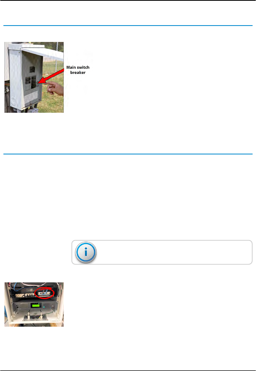
Activating the RMDC
To activate the RMDC, complete the following steps.
1. Open the door of the power box at the AC-power source.
2. Apply power from the main breaker switch as illustrated in
Figure 26.
3. Close the door of the AC-power box.
4. Turn on the disconnect switch.
5. Turn on the UPS using the internal on-off switch.
6. Connect the DC power cable to the bottom of the
RMDC.
Figure 26 – Main Breaker Switch
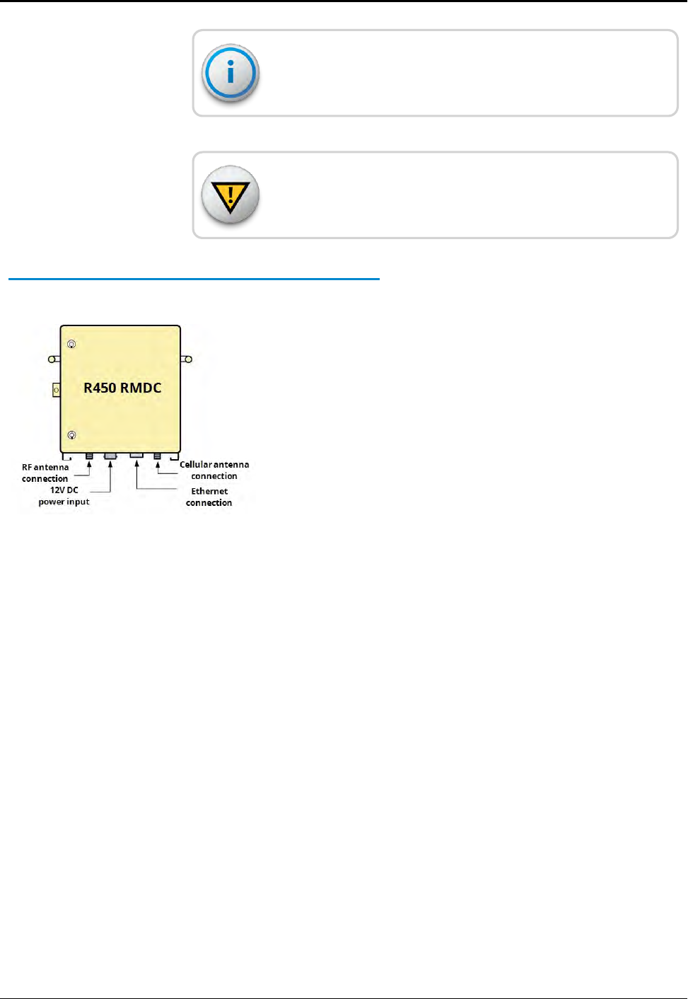
Configuring the Cellular Modem
The following list of equipment is needed to configure the cellular
modem.
lLaptop or PC with Ethernet network port
lCalAmp Vanguard modem and the modem's Quick Start Guide
lEthernet patch cable
To configure the modem, complete the following steps.
1. Follow the instruction provided in the CalAmp Vanguard
modem Quick Start Guide.
To use the modem, activate it for your specific carrier.
2. Turn off the power to the RMDC.
3. Remove the modem from the RMDC. See Figure 27.
Figure 27 – Modem in R450 RMDC
R450™Rack Mount Data Collector Installation and Maintenance Guide 29
Chapter 3: Installing theR450™RMDC
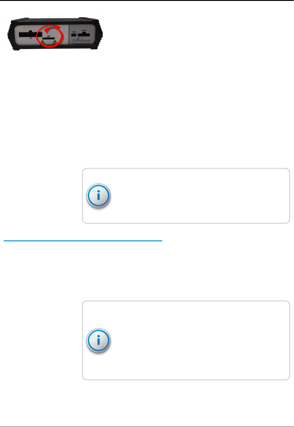
4. Insert the SIM card with the gold side up into the SIM card slot
on the back of the modem. Push the card completely into the
slot until it clicks in place. See Figure 28.
Figure 28 – Vanguard Modem Back Panel
5. Connect the modem to the laptop using the Ethernet cable.
6. Turn on the power for the RMDC.
7. Open a Web browser and in the address bar type the IP
address 192.168.1.50.
The connection log on window appears.
8. Type admin in the User Name field.
9. Type your password.
10. Click OK.
On the Unit Status page, the WAN status reads DOWN until the
cellular connection is enabled. Before activating the unit, select
your carrier(s), activate the modem, and if applicable, activate
your SIMcard.
Selecting the Carrier
To select a carrier, with the model still connected to the laptop
complete the following steps.
1. Select Cell Connection from the Main Navigation Panel and
select the Carrier tab.
2. Select your carrier from the list provided.
You cannot select the same carrier for primary and secondary.
Select Global System for Mobile communication (GSM) for any
GSMcarrier.
If you have more than one carrier, select whether the cell
connection is on the primary or secondary carrier, or enable
automatic switching, if possible.
30 R450™Rack Mount Data Collector Installation and Maintenance Guide
Chapter 3: Installing theR450™RMDC

3. Click Save.
This action refreshes the page. The information shown
depends on the carrier you selected.
4. Configure the applicable settings on the Settings tab, for each
carrier selected (primary or secondary).
Complete the following instructions that pertain to the carrier you
selected.
CDMA Settings (Provisioning) Verizon subscribers:
To provision the cellular modem using Code Division Multiple
Access (CDMA) setting, complete the following steps.
1. Make sure you have a strong or medium signal strength (dBm)
and not roaming.
2. Click the OTASP button to start the provisioning process.
3. Verify the unit status.
The status has updated to show a Mobile Directory Number
(MDN). If the number does not appear, your device did not
provision properly. Refer to the cellular modem's User Manual
for manual activation procedures.
GSM Settings (SIMCard Acceptance):
In the GSM settings, the SIMSTATUS reads SIMACCEPTED.
Configuration Complete
To verify the service is operational, open a browser on the laptop
and navigate to an active Web page (for example: Google.com). If
the service is not operational, contact the service provider.
Be sure to maintain the user name, password, and Access Point
Name (APN) information the cellular service provides.
R450™Rack Mount Data Collector Installation and Maintenance Guide 31
Chapter 3: Installing theR450™RMDC
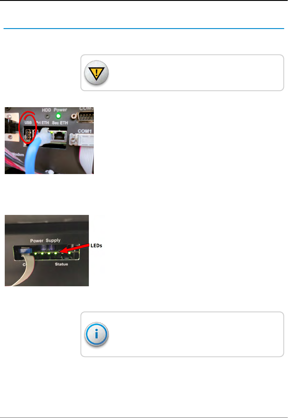
Configuring the Collector with the USB Flash Drive
To configure the RMDC with the USB flash driveComplete the
following steps.
CAUTION: Operators need to wear a grounded wrist strap to
mitigate the effects of Electro-Static Discharge (ESD).
1. Configure the USB flash drive (included with the RMDC) as
described in "USB Flash Drive Configuration for RMDC" on
page87.
2. Insert the configured USB flash drive into either one of the
two available USB ports on the CPU board.
Figure 29 – USB Port on CPU Board
3. Make sure the collector's internal power supply is fully off
before re-applying collector power. See Figure 30.
4. Cycle the power to the RMDC.
Figure 30 – Collector's Internal Power Supply LEDs
During configuration, the unit performs an automated self-
reset. The entire process takes approximately five minutes
without user intervention.
5. Remove the USB flash drive when configuration is completed.
32 R450™Rack Mount Data Collector Installation and Maintenance Guide
Chapter 3: Installing theR450™RMDC

Completing the Installation
After completing the wiring for the RMDC, you must verify that the
unit has been activated.
lTest the connections - lights and audible sounds. See"Testing the
Connections" below.
lSwipe a Meter Interface Unit (MIU) and receive the email the
host software automatically sends to the installer. See "Swiping
the MIU" on the next page.
Testing the Connections
Complete the following instructions to test the connections.
1. Wait approximately 60 seconds after you activate the
RMDC and listen for the sequence of several tones and beeps
that last approximately five seconds.
2. Check that the blue power light is on at the bottom of the
Midland Radio.
3. Check that the power light is on for the modem.
If the modem finds a network , the power light is solid. For
further details, refer to the modem's Users Manual.
4. If you use the Ethernet backhaul, check the status of the
Pri ETH Ethernet connector.
These lights provide a visual indication of the link status, and
network activity.
lThe green Link Integrity light is lit when a valid connection is
detected.
lThe yellow Activity light blinks on and off when activity is
detected on the wire.
Designator Light Color Description
Pri ETH Green Link Integrity
Pri ETH Yellow Activity
Table 9 – Lights on the CPU Board
R450™Rack Mount Data Collector Installation and Maintenance Guide 33
Chapter 3: Installing theR450™RMDC
5. After the RMDC has been powered up for five minutes, remove
the USB flash drive from the CPU board.
Connect only the Pri ETH Ethernet connector. Do not connect
any other component to the Sec ETH Ethernet connector.
Field Service Tool
Use the Field Service Tool (FST), Received Signal Strength Indicator
(RSSI), MIU Simulator,Collector, and Collector Monitor to verify the
RMDC is working properly. See the FST manual for instructions.
Swiping the MIU
Before you can proceed with these steps, the RMDC must be set
up in the N_SIGHT PLUS host software. See "Creating a
Collector" on page87 and "Building a USB Drive for Collector
Configuration" on page93 for instructions on setting up the
RMDC in the host software. In addition, confirm the
Configuration Packet Alarms are set in the host software. To set
the alarms, click the Endpoints tab, System Commands, and
then Alarm Notifications.
To verify that the RMDC can receive readings from MIUs and
can synchronize with the N_SIGHT PLUS host software,
complete the following steps.
1. Wait about five minutes after you have powered on the
RMDC.
2. Position the Neptune magnet against the left side of the
R450 MIU directly in line with the Neptune logo, as
shown in Figure 31.
3. Bring the magnet from the side and around the corner to
the top of the MIU to swipe it. See Figure 31.
Figure 31 – Activating the MIU
34 R450™Rack Mount Data Collector Installation and Maintenance Guide
Chapter 3: Installing theR450™RMDC
4. When swiped, the RMDC sends an email to the address set up
in the host software, similar to the following example.
Figure 32 – Email Sent from RMDC
lMake sure the email comes from the RMDC that you are
installing.
lIf you do not receive an email, follow the instructions
outlined in the next section.
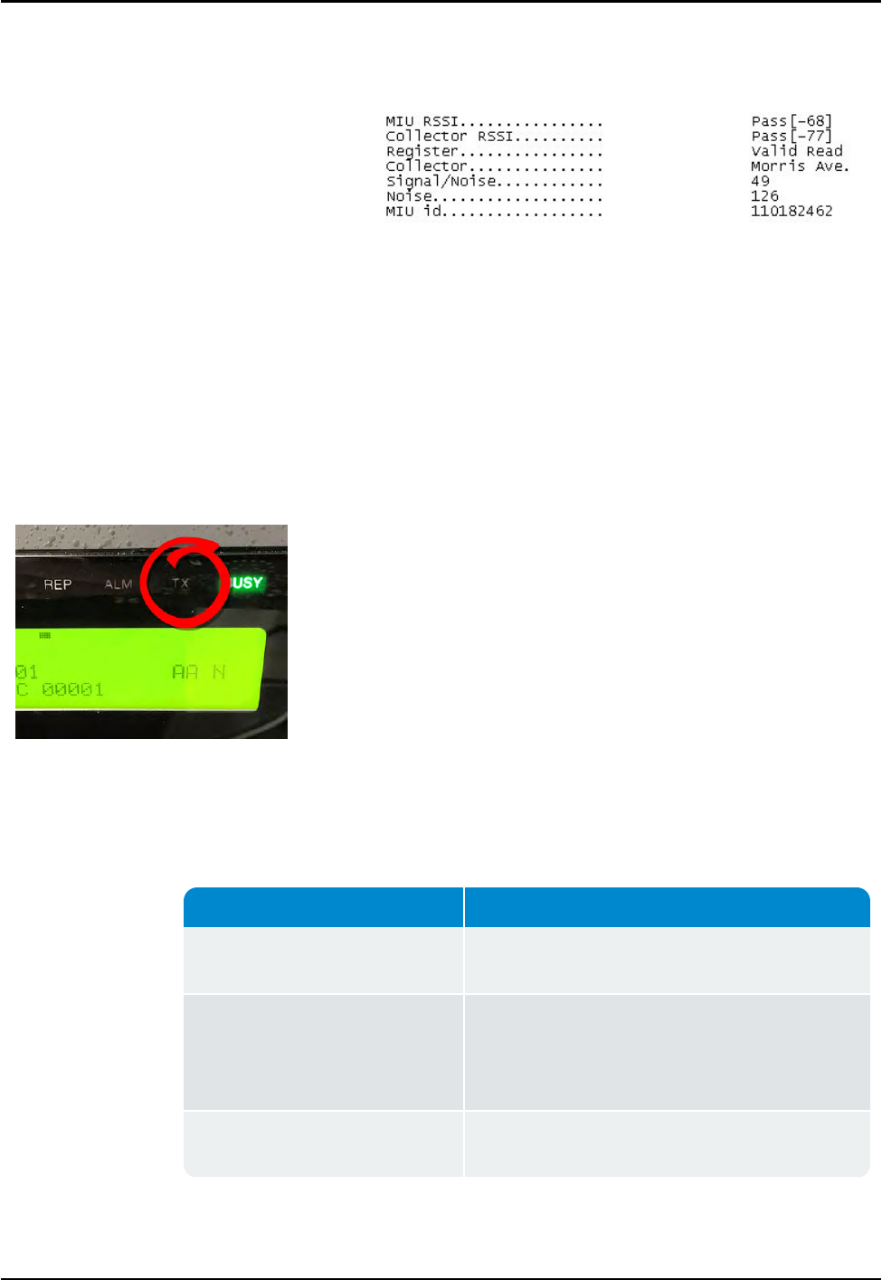
If You Do Not Receive an Email
If you do not receive an email, complete the following steps.
Figure 33 – Radio TXLight
1. Check to see if the Midland Radio is getting power by verifying
that the blue power light is on. See Figure 43 on page 55.
2. Check to see if the red Tx light of the Midland Radio is flashing
every 10 seconds. See Figure 33
If... Then...
The red Tx light is not flashing
every 10 seconds,
Call Neptune Customer Support. Refer to
"Contacting Customer Support" on page64.
The red Tx light is flashing every 10
seconds, but you do not receive
emails,
lThere could be a problem with the network
connection.
lThere could be a problem with the
N_SIGHT PLUS host software.
The problem is with the network
concordance,
Refer to "Verifying Connectivity" on page59.
Table 10 – Radio Tx Light - Identify Problem
R450™Rack Mount Data Collector Installation and Maintenance Guide 35
Chapter 3: Installing theR450™RMDC
If... Then...
The problem is with the
N_SIGHT PLUS host software.
lVerify the host software is configured to send
emails to the correct email address.
lCheck the host software to ensure the RMDC is
synchronizing. Refer to "Potential
RMDCProblems" on page52.
Table 10 – Radio Tx Light - Identify Problem (continued)
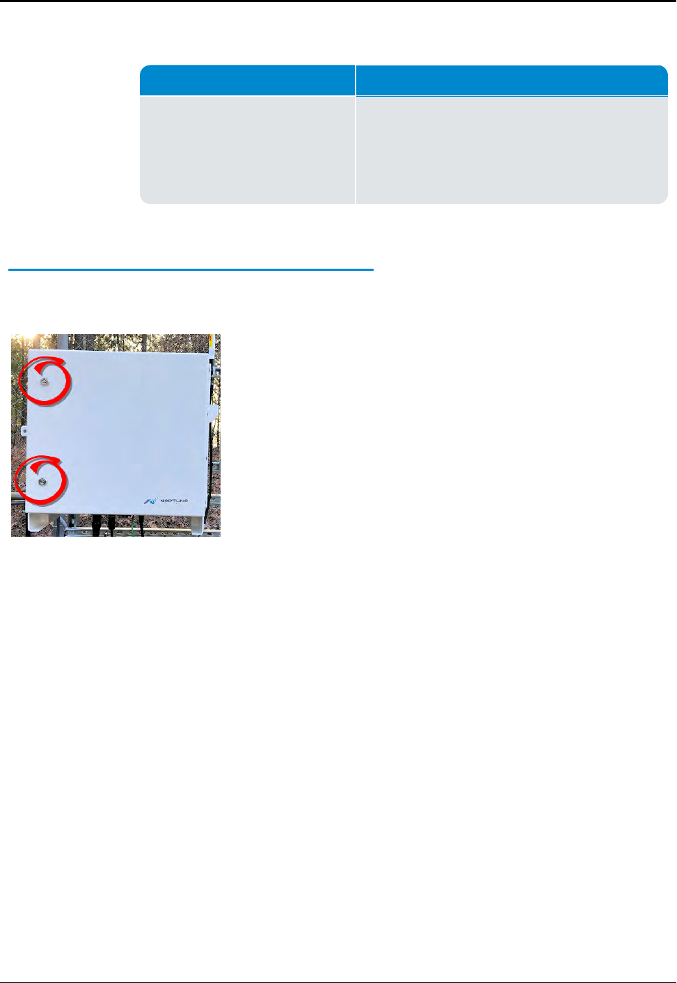
Securing the RMDC
After you finish the configuration, complete the following steps to
lock the RMDC.
1. Close the door of the RMDC.
2. Using the key that is supplied with the unit, secure both
door locks of the RMDC, as illustrated in Figure 34.
Figure 34 – Unit Door Locks
36 R450™Rack Mount Data Collector Installation and Maintenance Guide
Chapter 3: Installing theR450™RMDC
R450™Rack Mount Data Collector Installation and Maintenance Guide 37
Chapter 4: Uninterruptible Power Supply
This chapter describes the specifications for the Uninterruptible Power Supply
(UPS) or backup power solution. It also includes procedures for storing, unpacking
and inspecting, installing and connecting the UPS, plus descriptions of tools and
materials you use when working with the UPS.
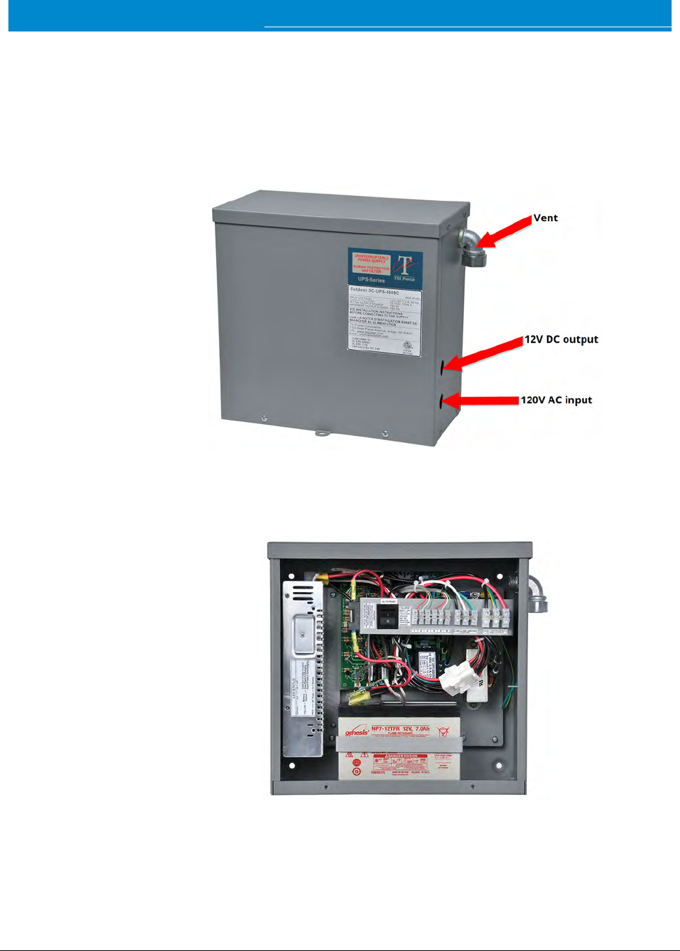
Figure 35 – Outdoor UPS (Closed)
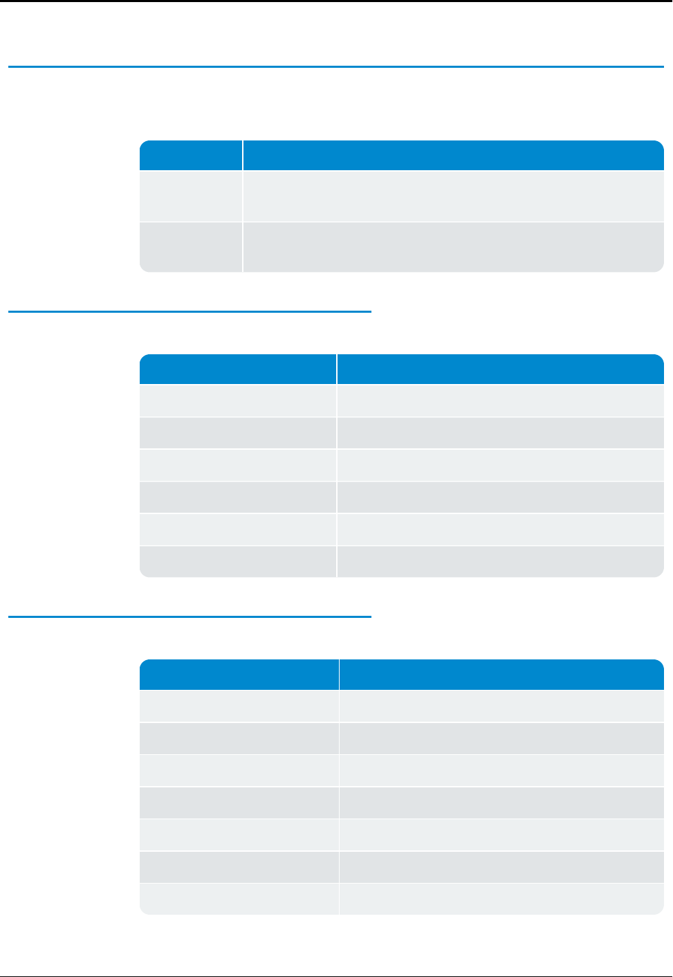
Figure 36 – Outdoor UPS (Cover Removed)
UPSSpecifications
This section provides information on the specifications of the UPS.
Specification Description
Neptune P/N: 13450-200 (includes pole/wall mounting bracket, DC power cord,
and stainless steel clamps)
UPS Topology AC to DC rectifier, battery charger, and sealed, valve-regulated, lead acid
batteries that are maintenance-free and rechargeable.
Table 11 – UPS Specifications
Input
Input Descriptions
Nominal Input Voltage 120 VAC
Operating Input Voltage Range 100 - 140 VAC
Input Current 6A
Operating Frequency 57 - 63 Hz
AC Input Surge Immunity ANSI / IEEE C62.41: 6 kV, 1.2 x 50 μs / 3kA, 8 x 20 μs
AC Connections Holes for 1/2" conduit connectors; wiring terminals
Table 12 – Input Specifications
Output
Specification Description
Nominal Output Voltage 12 VDC
Output Voltage Range 10 - 14 VDC
Output Current 13.04 A
Efficiency: Line / Backup 84 / 95.5%
Power On / Off Switch On / off rocker style power switch
Transfer Time to Backup 0 ms
DCConnections Holes for 1/2" conduit connectors; wiring terminals
Table 13 – Output Specifications
38 R450™Rack Mount Data Collector Installation and Maintenance Guide
Chapter 4: Uninterruptible Power Supply

Battery
Specification Description
Battery Type AGM(12 VDC 7 Ah x 2), sealed, valve-regulated lead-
acid (VRLA) battery that is maintenance-free and
rechargeable. (EnerSys Genesis P/N: NP7-12TFR)
Recharge Time to 90% 4 hrs
Battery Backup Time 24 min @ full load (13.04A)
Table 14 – Battery Specifications
Physical
Specification Description
Dimensions 12.5" (318 mm) wide x 12" (305 mm) high x 6.5" (165
mm) deep
Steel Cabinet All weather NEMA 3R design, UL 50E rain tested, pad
lockable enclosure
Weight 32 lbs (14.5 kg)
Mounting Option Pole or wall mounting bracket included
Table 15 – Physical Specifications
Safety
Specification Description
cETLus (Canada & US) ANSI / UL 60950-1, CAN / CSA C22.2: No. 60950-1-07 Clause
ANSI / UL 1778, CAN / CSA C22.2: No. 107.3-05 Clause
ANSI / UL 50E, CAN / CSA C22.2: No. 94-2-07 Clause
Table 16 – Safety Specifications
Environmental
Specification Description
Operating temperature l-40° to + 122° F (-40° to +50° C)
lWith BH5 optional battery heater
Table 17 – Environmental Specifications
R450™Rack Mount Data Collector Installation and Maintenance Guide 39
Chapter 4: Uninterruptible Power Supply
Checklists
This section provides safety checklists for:
lHandling the UPS and battery
lUnpacking and inspecting the UPS
UPSSafety Checklists
WARNING: The UPS should be installed by people trained in the
safe use of high-energy power supplies and their batteries. The
installer also should have knowledge of the local electrical
code(s) and their safe application.
To prevent accidental shorts, shocks, or electrocutions, never let
water enter the UPS. (Rain, a hose, tap, sprinkler output, or road
splash.)
Safety Considerations
Carefully unpack the components and report any shipping or other
damage immediately.
Always assume electrical connections or conductors are live. Turn off
all circuit breakers and double-check using a voltmeter before
performing installation or maintenance.
Before installation, verify the input voltage and current requirements
of the load meet the UPS's output (see specifications). Verify the line
voltage and current meet the UPS's input requirements.
Place a warning label on the utility panel to tell emergency personnel
a UPS is installed.
Use proper lifting techniques when lifting or moving the UPS or its
components.
Note that this UPS has more than one live circuit. DCpower can be
present at the output even if the UPS is disconnected from the DC
line.
Table 18 – UPS Safety Checklist
40 R450™Rack Mount Data Collector Installation and Maintenance Guide
Chapter 4: Uninterruptible Power Supply
Battery Safety Checklist
WARNING: Battery Emergency Procedures
lIf electrolyte splashes on your skin, immediately wash the
affected area with water.
lIf electrolyte gets into your eyes, wash them for at least 10
minutes with clean running water or a special neutralizing eye
wash solution. Seek medical attention immediately.
lNeutralize spilled electrolyte with special neutralizing
solutions in a "spill kit" or a solution of 1 lb. (0.45 kg) of baking
soda (bicarbonate of soda) in 1 gallon (3.9 L.) of water.
Battery Safety Conditions
Personnel knowledgeable about batteries and the required precautions needed to
install and service them.
Always replace batteries with the same type, numbers, and ratings. Never install old
or untested batteries. One sealed lead-acid battery is rated to a maximum voltage
of 12VDC.
CAUTION: A battery can present a risk of electrical shock and high short-circuit
current. Observe the following precautions when working on a battery.
lRemove watches, rings, or other metal objects.
lUse tools with insulated handles.
lWear rubber gloves and boots.
lDo not lay tools or metal parts on top of the battery.
lDisconnect charging source prior to connecting or disconnecting battery
terminals.
lDetermine if the battery is inadvertently grounded. If so, remove source from
ground.Contact with any part of a grounded battery can result in electrical shock.
To reduce the likelihood of shock, remove grounds during installation and
maintenance (applicable to equipment and remote battery supplies not having a
grounded supply circuit).
lNever dispose of batteries in a fire; they can explode. Follow the manufacturer's
directions for safe battery disposal.
lNever open or damage the batteries. Released electrolyte is harmful to the skin
and eyes and it can be toxic and hazardous to the environment.
Table 19 – Battery Safety Checklist
R450™Rack Mount Data Collector Installation and Maintenance Guide 41
Chapter 4: Uninterruptible Power Supply
Battery Safety Conditions
Never let live battery wires touch the UPS, the enclosure, or any other metal
objects. This can cause a fire or explosion.
Lead-acid batteries can release hydrogen gas. Never expose the UPS or enclosure
to open flames or sparks to prevent a fire or explosion.
Inspect the batteries once a year for signs of cracks, leaks, or swells. Replace as
needed.
If you have batteries in storage, charge them at least once every three months for
optimum performance and to extend their lifetime.
Table 19 – Battery Safety Checklist (continued)
Site Preparation Warnings
This section provides information on site preparation warnings.
Grounding
Consider the following warning concerning grounding the UPS.
WARNING: The UPS must be correctly grounded for proper
operation. Older facilities can have inadequate electrical
grounding. A qualified electrician must perform an inspection
before installation to ensure that grounding meets the local
electrical code.
42 R450™Rack Mount Data Collector Installation and Maintenance Guide
Chapter 4: Uninterruptible Power Supply
Branch Circuit Breaker Protection
Consider the following warning about branch circuit protection.
WARNING: To provide branch circuit protection, the utility line
attached to the UPS’s input must be protected by a circuit
breaker certified for this use and per the local electrical code. The
breaker’s minimum size is calculated by the following formula:
Minimum Breaker Size = UPS’s maximum input current / 0.8
The UPS’s maximum input current is read off the nameplate. For
example, if the nameplate gives the maximum input current as
6A, be sure the circuit breaker is rated at least 7.5A; however,
limit breaker size to a maximum of 15A.
Disconnects
Consider the following warning when installing the UPS.
WARNING: The AC input to the UPS must have a readily-
accessible disconnect device installed.
Mounting the UPS
This section provides information on mounting the UPS.
A pole / wall mounting bracket is included with the UPS.
R450™Rack Mount Data Collector Installation and Maintenance Guide 43
Chapter 4: Uninterruptible Power Supply
Wall Mounting
The UPS’s maximum input current is on the nameplate. For
example, if the nameplate gives the maximum input current as 6A,
be sure the circuit breaker is rated at least 7.5A.
Secure the UPS to the strut channel or wall using the
recommended hardware from Table 8 on page24.
Figure 37 – Strut Channel or Wall Mounting
The UPS utilizes the same strut channel or wall mounting
hardware as the RMDC.
Pole Mounting
To strap mount the UPS to the pole (4-inch to 16-inch diameter),
use the two stainless-steel clamps (included).
1. Attach the straps to the UPS mounting bracket.
2. Attach the UPS to the pole.
3. Tighten the straps using a flat-head (slotted) screwdriver.
Figure 38 – Pole Mounting Straps
44 R450™Rack Mount Data Collector Installation and Maintenance Guide
Chapter 4: Uninterruptible Power Supply
OPTIONAL: The UPS can be mounted to a large pole (4-inch or
larger) using two 3/4-inch wide stainless-steel straps (Band-It
#C20699 strap, #C25699 buckle, and #C00169 standard tool).
The strap, buckle, and tool are supplied by other vendors.
To secure the UPS to a small pole (2-inch to 4-inch), use the
recommended hardware from Table 6 on page16. Also
reference Appendix E: Strut Clamp Recommendations.
Connecting the UPS
This section provides information on the tools, materials, and
procedures are needed to connect the UPS.
Tools and Materials Required
The following list describes the tools and materials needed to
connect the UPS.
lSlotted-tip screwdrivers for tightening screws on terminal blocks
lAC/DC voltmeter
l#2 Phillips Head screwdriver for removing the cover
lChannel lock pliers for tightening cord grip and jam nut
R450™Rack Mount Data Collector Installation and Maintenance Guide 45
Chapter 4: Uninterruptible Power Supply
Procedure
To wire the input and output connectors, complete the following
steps.
Wiring the Input and Output Connectors
1. Remove the two screws that secure the UPS cover.
2. Remove the UPS cover.
Figure 39 – Wire Input and Output Connectors
CAUTION: The UPS contains a vent on the upper right side of the
case; do not remove this.
Installing and Wiring the UPS
1. Install Liquid-Tight Flexible Non-Metallic Conduit from the
disconnect switch to the lower 1/2-inch conduit hole on the
side of the UPS.
2. Install the black, white, and green wires through the conduit
and terminate to the terminal block inside the UPS.
3. Install the DC cord grip in the upper 1/2-inch conduit hole on
the side of the UPS; just above the conduit.
4. Route the open pigtail end of the DC power cable through the
cord grip and terminate to the DC terminal block inside the
UPS.
5. Tighten the DC cord grip using pliers or a wrench.
6. Attach the power cord to the bottom of the RMDC.
46 R450™Rack Mount Data Collector Installation and Maintenance Guide
Chapter 4: Uninterruptible Power Supply
Powering On the UPS
To turn the UPS on, complete the following steps .
1. Turn the UPS power switch ON.
2. Re-install the UPS cover and secure it with the two screws.
Servicing the UPS
This section provides information on servicing the UPS.
CAUTION: Before attempting to service the UPS, verify that the
disconnect device is turned OFF. Also verify that the UPS switch is
turned OFF.
Checking UPS Status LEDs
This section provides information on checking and troubleshooting
the UPS.
If the RMDC does not power up, complete the following steps to
check the UPS status.
1. Remove the power plug from the bottom of the RMDC.
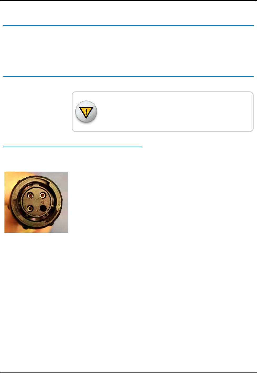
2. Measure between pin-1 (+) and pin-2 (-) on the plug.
The voltage measures 13.5-14.4 VDC. See Figure 40.
Figure 40 – RMDC Power Plug
R450™Rack Mount Data Collector Installation and Maintenance Guide 47
Chapter 4: Uninterruptible Power Supply
If Then
The voltage measurement is good There is a problem with the RMDC. Refer to
"Troubleshooting" on page 51.
The voltage is negative There is a problem with the UPS wiring.
Complete the following steps.
lRemove the UPS cover.
lCorrect the wiring issue.
lRecheck wiring.
There is no voltage present or the
voltage is low (< 10.5V DC)
Complete the following steps.
lRemove the UPScover.
lVerify the internal power switch is ON.
lCheck the status LEDs inside the UPS.
See Table 21 .
Table 20 – RMDC Does not Power Up
LED Indicators Description
Green Solid on = AC is good
Off = AC failure
Yellow Solid on = battery fully charged
Blinking slowly = battery charging
Blinking rapidly = battery discharging (possible AC input voltage
failure)
Red Faulty DCoutput = fuse can be blown
Table 21 – UPS Status LEDs
5. Verify the UPS is producing the correct voltage at the output
terminals by measuring across DC+ (red) and DC- (black).
The voltage measures 13.5-14.4 VDC.
This step assumes the AC input voltage is present and the UPS
internal switch is ON (battery is charging).
48 R450™Rack Mount Data Collector Installation and Maintenance Guide
Chapter 4: Uninterruptible Power Supply
If the Then
AC input voltage is not present The voltage across DC+ (red) and DC-
(black) measures 10.5-12.8 VDC.
Voltage is less than 10.5 VDC The battery is fully discharged and must be
recharged. Complete the following steps.
1. Measure the AC input voltage across
L1 and N1.
Verify that the voltage measures
100-140 VAC.
2. Verify the UPS's internal switch is
ON.
3. Check the UPS status LEDs. See
"UPS Status LEDs" on the previous
page.
Table 22 – Verify UPS is Producing Correct Voltage
Checkup Complete
After completing the UPS diagnostics, perform the following steps.
1. Re-install the UPS cover.
2. Secure cover with two screws.
The batteries in the UPS have an expected life span of three to
five years in float service applications. Length of service life is
directly affected by the number of discharge cycles, depth of
discharge, ambient temperature, and charging voltage.
R450™Rack Mount Data Collector Installation and Maintenance Guide 49
Chapter 4: Uninterruptible Power Supply

This page intentionally left blank.
Chapter 4: Uninterruptible Power Supply
50 R450™Rack Mount Data Collector Installation and Maintenance Guide
R450™Rack Mount Data Collector Installation and Maintenance Guide 51
Chapter 5: Troubleshooting
This section provides information for possible symptoms, areas of focus, and
actions to resolve problems that can arise with your R450™ Rack Mount Data
Collector (R450 RMDC).
WARNING: Neptune does not recommend servicing an RMDC during inclement
weather.
Equipment Required
The following items are required to troubleshoot the RMDC.
lKeys to access the site and open the RMDC cabinet
lDigital Multimeter with long leads
lVoltage Standing Wave Ratio (VSWR) meter
lSockets and open-end wrenches to install / remove the RMDC
lSmall, medium, and large standard screw drivers
l#1 and #2 Phillips head screw drivers
lElectrical tape and wire ties
lA backup RMDC, if one fails
lRMDC configuration USB flash drive (included with the RMDC)
The USB flash drive must be configured for the specific RMDC.
lAnti-static wrist strap and ground lead with alligator clip for attaching the wrist
strap to the RMDC cabinet
lMIU configured for site
lMagnet to swipe the MIU
lR450 System Field Service Tool (FST)
PC Notebook Configuration
To use a notebook computer, consider the following for the
CalAmp Cellular Modem:
lRequires an Ethernet patch cable to connect to the network port
of the computer.
lUses a Web-based application, not software, for configuration.
Refer to the cellular modem's Quick Start Guide for log on and
setup instructions.
Potential RMDCProblems
The following sections describe problems that can arise and how
to handle these potential problems.
Multiple RMDC Not Syncing with Host Database
The following issues can cause syncing problems:
lHost database server is down or not connected to the Internet.
lRemote Internet, phone, cable, or cell service provider is either
down or experiencing degraded service.
lMultiple power outages affecting several sites.
Storm Damage Affecting Multiple Sites
One RMDC is not syncing with the host database. Troubleshooting
this problem requires going to the RMDC site.
First Steps
Before leaving for the site, assess the health of the RMDC using the
host system.
For instructions on how to assess the health of the RMDC, refer
to "Using System Health" in the "System Health" topic of the N_
SIGHT®PLUS Online Help.
52 R450™Rack Mount Data Collector Installation and Maintenance Guide
Chapter 5: Troubleshooting
lIf the RMDC is offline, this indicates that external power, internal
power, CPU, relays, or the backhaul modem is not functioning.
lSome sites are configured so operators can log on to the
RMDC remotely. Look at the logs, and watch the system activity. If
the RMDC is offline but it is still possible to log on the system, this
indicates that the computer and backhaul modem are both
functional.
Initial Site Activities
lOpen the RMDC and inspect the equipment.
lMake sure that there is no obvious physical damage to the
system, condensate or standing water. For example, burned
components or wires can indicate a direct or nearby lightning
strike. If there is any evidence of physical damage, replace the
RMDC with the spare and contact Neptune to request a Return
Material Authorization (RMA) to return the damaged collector.
CAUTION: The ground wrist strap must be clipped to the RMDC's
ground system. Do not touch the computer circuit board or any
of the components if you are not wearing the wrist strap. Failure
to use the strap can cause damage to the computer due to static
electricity discharge.
Checking the General Health of Each Module
This section provides information on the general health of the
R450 RMDC's internal modules.
CPU Board Power and Activity Visual Check
There are two Light Emitting Diodes (LEDs) above the CPU board.
See Figure 41 on page 54.
lGreen Power LED
lRed HDDLED
The green LED is lit if power is applied to the CPU board. The red
LED flashes intermittently to indicate hard drive and CPU activity.
R450™Rack Mount Data Collector Installation and Maintenance Guide 53
Chapter 5: Troubleshooting
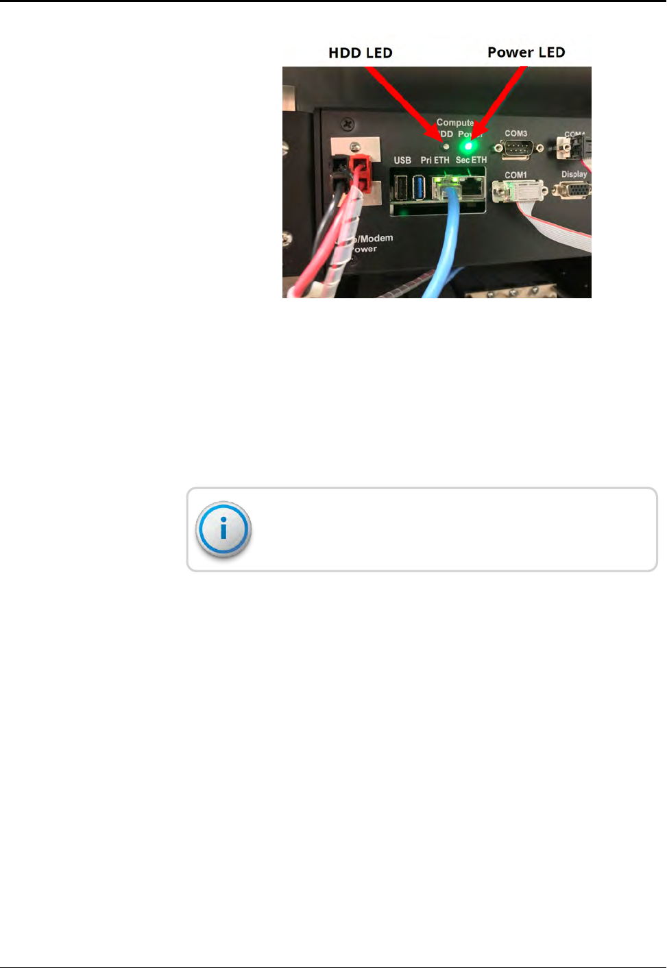
Figure 41 – LEDs Above CPU
There are two additional Ethernet status LEDs:
lOne to the left of the primary Ethernet RJ45 connector that
indicates an active link when lit.
lOne to the right of the same connector that indicates
communication activity.
Connect the Ethernet cable to the PriETH port. Connection to
the Sec ETH port can cause unreliable operation.
When functioning properly, the link LED is steadily lit and the
activity LED intermittently. Random flashes indicate live network
activity. See Figure 42 on page 55.
54 R450™Rack Mount Data Collector Installation and Maintenance Guide
Chapter 5: Troubleshooting
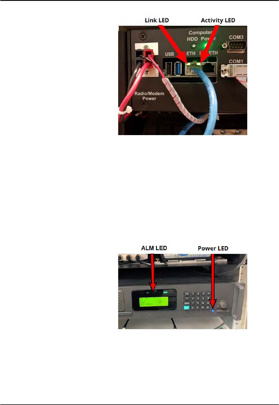
Figure 42 – Ethernet Status LEDs
Radio Power Visual Check
The radio has several indicator LEDs on the front panel. The power
LED should be lit blue. See Figure 43. If the amber ALM LED is on or
flashing:
lThe radio may be malfunctioning.
lThe R450 RMDC may be operating on UPS backup power in the
event of a main power failure.
Figure 43 – Radio LEDs
R450™Rack Mount Data Collector Installation and Maintenance Guide 55
Chapter 5: Troubleshooting
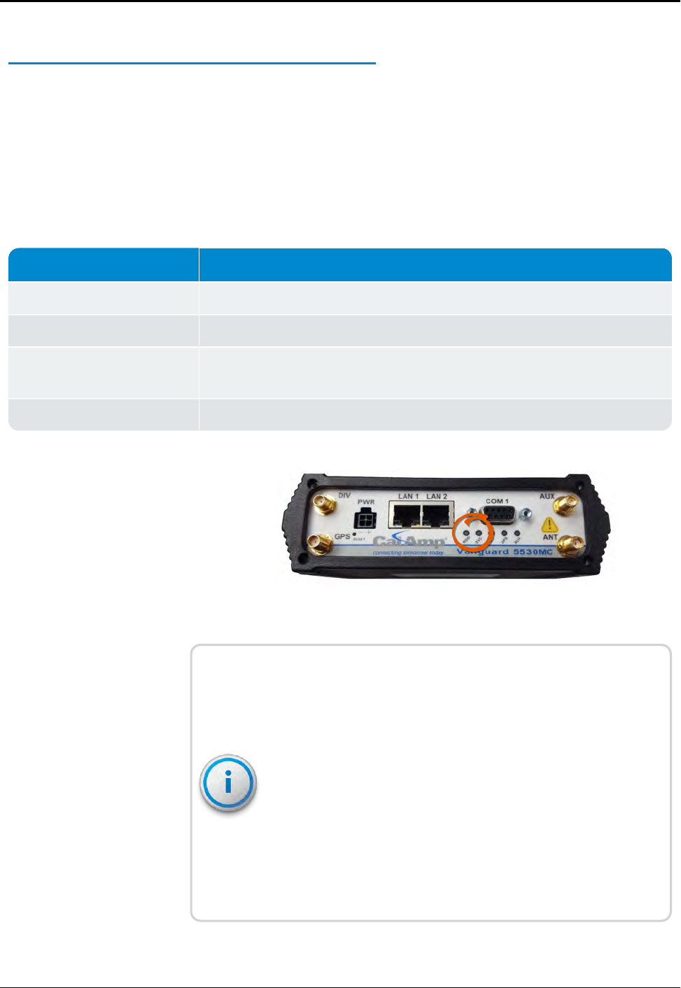
Checking the Backhaul Modem Power and Connectivity
This section provides information on visually checking the backhaul
modem.
CalAmp Vanguard Modem Visual Check
Look at the indicator LEDs on the modem to verify that the modem
is working. See Figure 44 on page 56.
If the Then
RSSI and SVC LEDs are on The modem is powered.
RSSI and SVC LEDs are not on There is a power problem with the modem. Verify that the main power is on.
SVC LED is solid The modem is connected to the cellular network. See Table 24 on the facing
page.
SVC LED is flashing The modem is trying to connect to the network. See Table 24 on the facing page
Table 23 – Visual Check Modem RSSI and SVC LEDs
Figure 44 – Modem Indicator LEDs
The LED behavior is different thanTable 24 on the facing page at
boot (initial power-up). The proper sequence is:
lAll red LEDs
lAll amber LEDs
lOff for a moment
lAll green LEDs
lAll green LEDs flash three times
This indicates a successful Built-In-Self-Test (BIST) and a healthy
modem.
56 R450™Rack Mount Data Collector Installation and Maintenance Guide
Chapter 5: Troubleshooting
Function Off Green Flash
Green Red Flash
Red Amber Flash
Amber
RSSI Strong Weak/None Medium
SVC (cellular
network
connection)
4G NC NC 3G/2G NC
NET No connectivity Rx data Tx data Rx/Tx
GPS Disabled Fix Search no fix
AUX Disabled Good Failed
Table 24 – Modem Status LEDs
The CalAmp Vanguard 5530MC includes a multi-carrier feature
which provides more choice in carrier networks and delivers 4G
LTE performance with automatic fallback to 3G and 2G legacy GSM
and CDMA networks.
Additional Detail Checks
If any of the previous checks failed, perform the following detail
checks. Perform power supply voltage checks one at a time so that
a load remains on the power supply. This is especially important
for the CPU and modem voltage checks. With no load on the
power supply, erroneous values can be measured.
Verify Main Power
It is a good practice to check the main power and make sure it is
within specification. If there are no power indications on the RMDC,
complete the following.
1. Verify there is power on the upper front panel of the
RMDC. Measure the DC voltage at the black and red
Anderson connector labeled "Power" on the right side of the
front panel. This voltage should measure 13.5 to 14.4V DC
when the UPS is switched on and main power into the UPS is
present. See Figure 45.
Figure 45 – Radio Modem Power Front Panel Connector
R450™Rack Mount Data Collector Installation and Maintenance Guide 57
Chapter 5: Troubleshooting
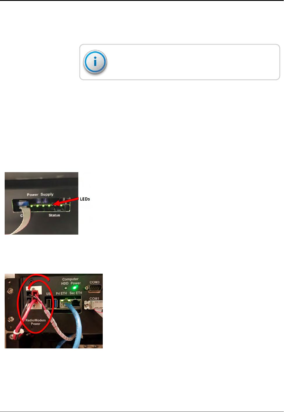
2. Verify the main AC power disconnect device is turned ON.
3. Verify the UPS output voltage. Refer to the "Checking UPS
Status LEDs" on page47.
The RMDC is capable of functioning on voltages as low as
10VDC.
If voltage is not present at the R450 RMDC main power
connector, switch OFF the UPS, disconnect the power harness
from the R450 RMDC power connector, and ohm-out the
harness to the UPS +12VDC terminals. An open or high
resistance indicates damage to either the internal or external
power harness.
Verifying Switched DC Power
To verify switched DC power, complete the following steps.
1. Turn on the UPS and wait approximately 60 seconds for the
R450 RMDC to power up.
The two right-most green LEDs should flash during this initial
60-second power-on delay.
2. Verify the R450 RMDC internal power supply's four left-most
green LEDs are lit. See Figure 46.
Figure 46 – RMDC Power Supply
If the LEDs are lit, complete the following steps.
3. Verify there is Switched DC power on the upper front panel of
the RMDC at the Radio / Modem Power Anderson power
connector.
4. Measure the voltage at the black and red Anderson
connector labeled "Radio/Modem Power".
The voltage should measure between 13.5 VDC and 14.4
VDC. If the voltage is above or below these values, the internal
power relays or UPS may be defective. Contact Neptune
Customer Support for additional guidance.
Figure 47 – Radio Modem Power Front Panel Connector
58 R450™Rack Mount Data Collector Installation and Maintenance Guide
Chapter 5: Troubleshooting
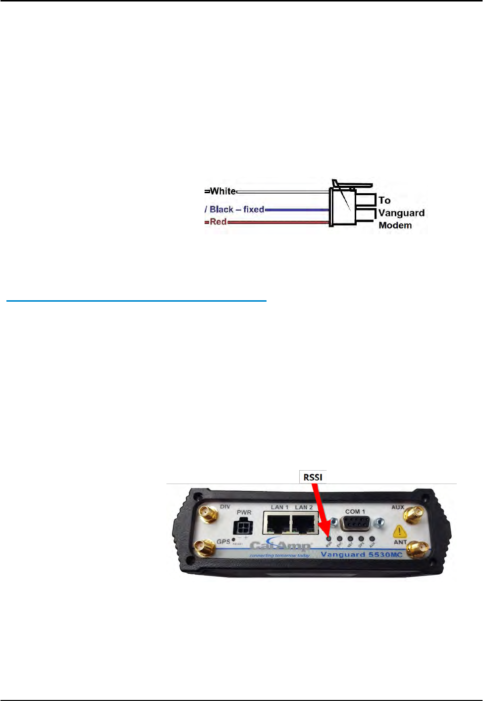
Verifying Cellular Modem Power
To verify cellular modem power, complete the following steps.
1. Disconnect the power harness from the cellular modem (black
4-pin Molex connector).
2. Verify the voltage is 13.5 VDC to 14.4 VDC between the red and
black contacts.
3. Verify the voltage is 13.5 VDC to 14.4 VDC present between the
white and black contacts.
Figure 48 – Vanguard Modem Power Connector
Verifying Connectivity
CalAmp Vanguard Modem
To verify connectivity and signal levels, complete the following
steps.
1. Locate and identify the RSSI LED light on the modem.
2. Identify the RSSILED light:
lSolid = indicates signal strength is strong
lBlinking = indicates signal strength is medium
lOff = indicates signal strength is poor, or no signal at all
Figure 49 – CalAmp Vanguard Modem with RSSI LED
R450™Rack Mount Data Collector Installation and Maintenance Guide 59
Chapter 5: Troubleshooting
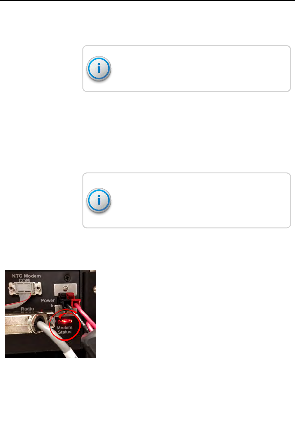
If the signal strength is poor or if there is no signal at all, there can
be something wrong with the antenna. It is also possible that the
local cellular service is not working.
For more detailed information on your wireless connection
status, connect to the modem's configuration application. Refer
to "Configuring the Cellular Modem" on page29.
Ethernet
If you use an Ethernet backhaul, then check the status lights on the
CPU board. Refer to "Testing the Connections" on page33.
Verifying Radio and NTGModem Functionality Using the MIU
To verify that the system is functioning properly, complete the
following steps.
For this test to be valid, the R450 RMDC must send regular time
beacon transmissions. This is indicated by the TX indicator
flashing every ten seconds. See Figure 43 on page 55. If the
RMDCdoes not send time beacons, it automatically fails the test.
1. Obtain a magnet and MIU.
2. Swipe the magnet across the MIU so that it sends out a
configuration packet.
3. Watch for the NTG Modem Rx/Tx LED "couplet" in the
Modem Status Window. This happens within a minute of
swiping the MIU.
lThe Rx LED flashes followed immediately by a flash of the
Tx LED. See Figure 50.
lIf the couplet is not observed or only the Rx LED flashes,
there is an internal problem with the RMDC that can
include its configuration, the radio, NTG modem, or the
computer.
Figure 50 – NTG Modem Status LEDs
60 R450™Rack Mount Data Collector Installation and Maintenance Guide
Chapter 5: Troubleshooting
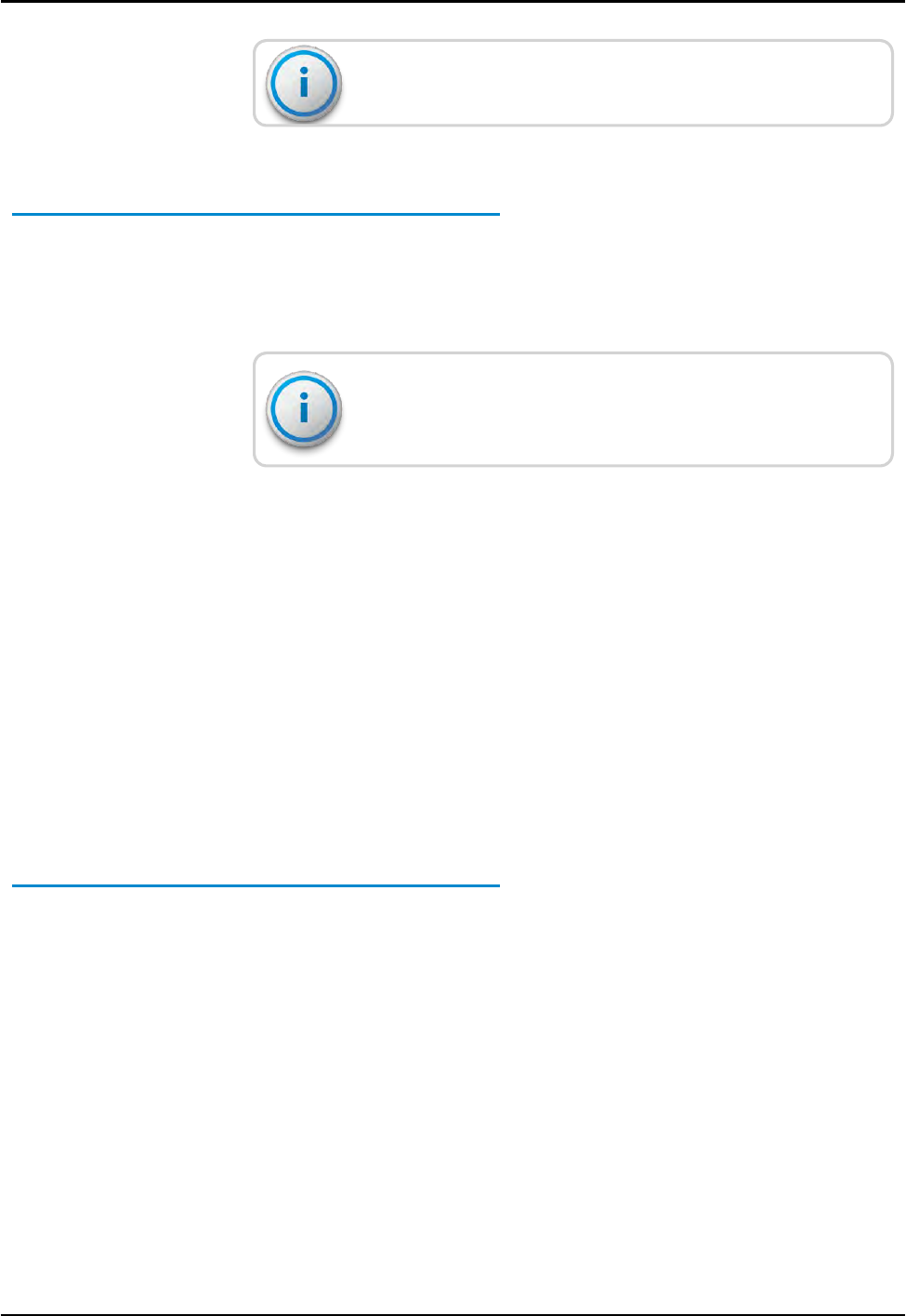
The radio's BUSY indicator can be constantly lit. This is normal.
RMDC is Syncing but Not Supplying MIU Data
If the RMDC is online, this indicates that the computer and the
backhaul modem are both working. If the RMDC collects no
readings, this indicates that there is a potential problem with the
radio and modem.
Troubleshooting this problem requires going to the
RMDC site.
Initial Observations
After opening the cabinet, assess the following.
lThe RMDC sends out a time beacon every ten seconds. The
transmit light on the radio and the NTGmodem's Tx LED flashes
every ten seconds. See "Radio LEDs" on page55. Only the red
transmit indicator should flash. If the amber ALM indicator
flashes at the same time, this indicates that there is a problem
between the radio's transmitter and the RF antenna.
lIf the transmit indicator does not flash, this indicates that there is
a potential problem with the NTG modem, the computer, or the
I/O harness to the NTG modem.
Radio Transmits but ALM Indicator Flashes
This requires measuring the VSWR of the antenna system. If the
VSWR is greater than 1.5:1, it indicates there is a problem with the
RFsurge arrestor, feed line or the antenna.
Measuring the VSWR
To measure the VSWR using the MFJ-269 SWR Analyzer, complete
the following steps.
1. Make sure the red Power button is off. The red button is
extended outward.
2. Press the UHF button to be sure it is extended outward.
R450™Rack Mount Data Collector Installation and Maintenance Guide 61
Chapter 5: Troubleshooting

3. Turn the Frequency knob fully counter-clockwise. This knob
points to 114-170/UHF.
4. Connect the 2-inch attenuator pad to the Antenna Connector.
Leave the other end open.
5. Press and lock the red Power button and the black UHF button.
6. Adjust the Tune knob to the desired frequency. Sweep the
entire 450 - 470 MHz range.
7. Observe the indicated VSWR to ensure it reads 3.0 ± 0.2.
This indicates that the unit is calibrated correctly and the
batteries are good.
8. Do one of the following:
lIf the reading is outside this range, then try replacing the
batteries (eight AA batteries). If this does not improve the
readings, the unit needs to be recalibrated.
lIf the reading is within the range, go to step 9.
9. Power off the unit.
10. Remove the attenuator pad and connect the antenna from the
bottom of the collector.
11. Press and lock the red Power button and the black UHF button.
12. Adjust the Tune knob for desired frequencies. Look at both the
collector receive and transmit frequencies.
13. Observe the indicated VSWR.
A value of 1.0 is ideal but not practical. Typical values are 1.1 to
1.2 for a healthy antenna system.
13. When finished, power off the unit.
If a flashing SLP indicator appears in the bottom-right corner of
the display, this indicates Sleep mode. Simply turn the unit off
and then on again.
The Radio Never Transmits
The simplest test is to cycle power on the RMDC to see if the radio
starts transmitting.
It can take up to ten minutes for the RMDC to be fully functional.
62 R450™Rack Mount Data Collector Installation and Maintenance Guide
Chapter 5: Troubleshooting

lIf the radio starts transmitting, this indicates that there was a soft
failure in one of the serial ports possibly related to the effects of
a storm.
lIf cycling the power does not fix the problem, the RMDC has an
internal problem, either with the computer, the NTG modem, or
the modem's I/O harness. Return the RMDC for repair.
Reduction in Amount of Data Collected
If the RMDC is not collecting as much data as before (but it is still
collecting some MIU data), this usually indicates that there is a
problem with the antenna and feedline system. It could also
indicate an internal problem. To determine the cause of the
problem, complete the following steps.
1. Check all the system voltages as outlined above.
2. Measure the VSWR following the steps on the previous page.
If the VSWR is high, have qualified radio personnel check out
and certify the feedline and antenna.
3. Check the power ouput.
If the power output is low, place the wattmeter between the
duplexer and the surge protector to make a second VSWR.
If the VSWR measures much higher before the surge
suppressor, the suppressor can be damaged.
If there is still a reduction in data collected, most likely there is a
problem with the duplexer or radio. Contact Customer Support.
R450™Rack Mount Data Collector Installation and Maintenance Guide 63
Chapter 5: Troubleshooting

Contacting Customer Support
Within North America, Neptune Customer Support is available
Monday through Friday, 7:00 AM to 5:00 PM Central Standard
Time by telephone, email, or fax.
By Phone
To contact Neptune Customer Support by phone, complete the
following steps.
1. Call (800) 647-4832.
2. Select one of the following options:
lPress 1if you have a Technical Support Personal
Identification Number (PIN).
lPress 2if you do not have a Technical Support PIN number.
3. Enter the six-digit PIN and press #.
4. Select one of the following options.
lPress 2for Technical Support.
lPress 3for maintenance contracts or renewals.
lPress 4for Return Material Authorization (RMA) for Canadian
accounts.
You are directed to the appropriate team of Customer Support
Specialists. The specialists are dedicated to you until the issue is
resolved to your satisfaction. When you call, be prepared to give
the following information.
lYour name and utility or company name.
lA description of what occurred and what you were doing at
the time.
lA description of any actions taken to correct the issue.
By Fax
To contact Neptune Customer Support by fax, send a description
of your problem to (334) 283-7497. Please include on the fax
cover sheet the best time of day for a customer support specialist
to contact you.
By Email
To contact Neptune Customer Support by email, send your
message to support@neptunetg.com.
64 R450™Rack Mount Data Collector Installation and Maintenance Guide
Chapter 5: Troubleshooting
R450™Rack Mount Data Collector Installation and Maintenance Guide 65
Appendix A: RF Antenna Installation
RF Antenna Overview
There are a number of critical items you must consider when placing and installing
the antenna. The following topics contain items that can influence the antenna
placement and installation.
Mounting the Antenna
To mount the antenna, complete the follow these steps.
1. Mount the antenna as high as possible with an unobstructed view of the
coverage area.
lThe supporting structure, if the antenna is not mounted above it, can cause
specific areas of limited coverage.
lA water tower in particular can severely limit coverage where the signal must
pass directly through the tank. When mounting the antenna on a water tower,
Neptune recommends mounting it on top as close to the center as possible.
lWhen mounting the antenna on a traditional three-leg or four-leg tower,
position the antenna using a standoff mount at least 5 feet away from the
tower to minimize coverage area problems.
2. Avoid making the RMDC antenna the tallest point in the surrounding area to
decrease the potential of the antenna being damaged by lightning.
WARNING: Do not mount antennas on utility poles, electric service masts, or
other structures carrying electric light or power wires. Coaxial cables must
maintain clearance of:
lAt least 2 feet (0.6 m) from power or light wires carrying 250V or less.
or
lAt least 10 feet (3.0 m) from power wires carrying more than 250V, per NEC,
Article 810, CEC Section 54.
Mounting the Antenna Mast
When mounting the antenna and antenna mast, it is important to
maximize the line-of-sight relationship between the RF 450™ MHz
antenna and R450 MIUs for optimum RF communications.
WARNING: The antenna mast and stand must be grounded to
the same grounding electrode used for the building's electrical
system. This ensures that all exposed, non-current-carrying
metal parts are the same potential. Refer to NEC Article 810 and
CEC Section 54.
WARNING: Antenna contact with high voltage wires can result in
death. Watch for overhead electric power lines when erecting
the antenna and mast.
Site Recommendations
The following are recommendations for sites with multiple
transmitters, receivers, and antennas. These sites require extra
care when determining a location to install the antenna.
lAvoid mounting the RMDC antenna so that it is at the same
height as another antenna on the site, regardless of the
frequencies.
lOn sites that have multiple antennas, if possible, mount the
antennas one above the other, separating each by at least 10
feet vertically. This minimizes the interference between the
systems.
lFor cellular antenna sites, mount the RMDC antenna either
above, below, or in the middle of the ring of cellular antennas.
The two systems can coexist without interference.
lAntenna sites that must share space with multiple transmitting
systems can require additional equipment to protect the
systems from interfering with each other. These sites can also
require additional engineering to make them perform well.
66 R450™Rack Mount Data Collector Installation and Maintenance Guide
Appendix A: RF Antenna Installation
lSites with multiple radio systems that are already operating on
the 450 - 470 MHz band can combine the signals into one
antenna system using the appropriate equipment. This often
works better than attempting to protect the individual systems
from interfering with each other.
lManaged antenna sites can require additional equipment and
dictate the installation. As long as the installation meets
Neptune's minimum requirements, follow the site's
requirements as recommended.
Feed Line and Antenna Recommendations
CAUTION: Neptune recommends that you consult with a
qualified installer on the design and installation of the antenna
system. If the installer is already familiar with the site and the
existing equipment, this can make the installation go more
smoothly.
Feed Line
The feed line is a significant contributor to both good and poor
system performance. A properly installed feed line is critical to
optimal system performance. Testing the antenna while it is on the
ground can ensure the system is working properly.
Installation of the connectors is best done with the proper tools
and a trained installer. With the proper tools and jigs, installing
coaxial connectors takes only a few minutes each. Not using the
proper tools as recommended by the manufacturer can potentially
cause problems, either immediately or after several years of proper
operation.
Feed Line Requirements
Consider the following feed line requirements.
lThe installer must certify the antenna and feed line system
installation (after it is completed) to ensure it performs according
to specifications.
lThe maximum loss for the feed line and connectors must be less
than 3 dB.
R450™Rack Mount Data Collector Installation and Maintenance Guide 67
Appendix A: RF Antenna Installation

lBond the feed line at the top of the tower and at the base of the
tower. Use Andrew / CommScope grounding kits and
procedures for all bonds.
lFor towers over 150 feet tall, bond the feed line at regular
intervals down the tower. The general recommendation is that
the feed line be bonded every 50 feet to 75 feet. Site
requirements and standard practices always dictate the
configuration.
lYou can install an optional surge protector on the tower near
the antenna to help protect the feed line.
lFor the AVA5-50 cable or larger, use jumpers to go between the
larger cable and the RMDC and antenna connectors. Jumpers
provide coaxial cable downsizing for the last 6 feet of the
installation, allowing a more flexible and manageable
connection to the RMDC.
lAndrew provides installation instructions for the Heliax coaxial
cable. See Bulletin 17800B Revision C. Neptune Customer
Support can supply a PDF copy .
Cable Guidelines
Prepare the cable for installation, and check for damage. You need
the following materials to install the cable.
Action Material Needed
Hoisting the Cable lHoist lines
lPulleys
lCable reel
lHoisting grips
Anchoring Cable lCable hangers
l3-feet to 4-feet intervals or as recommended by the coax cable
manufacturer
Grounding Coax ground kits (top, bottom, building entrance)
Horizontal Cable
Runs
lAbove ground - ice bridge
lBuried cable - conduit or sand below the frost line or one meter
Table 25 – Material Needed for Cable Installation
68 R450™Rack Mount Data Collector Installation and Maintenance Guide
Appendix A: RF Antenna Installation
Action Material Needed
Cable Connections lConnector installation instructions
lConnector torque
lWeatherizing kits
Measurements lReturn Loss (VSWR)
lDistance to Fault (DTF)
Table 25 – Material Needed for Cable Installation (continued)
Neptune Part Numbers
The following table provides Neptune part numbers for cable.
Neptune
Part Number
Coax
Diameter
Loss per
100'
Minimum
Bend Radius
Weight per
Foot
Maximum
Length Notes
10046-119 1/2" 1.45 dB 5" 0.15 150' Recommended
antenna cable for
150' cable runs or
less
10046-118 7/8" 0.74 dB 10" 0.30 400' Recommended
antenna cable for
runs over 150'
Table 26 – Neptune Part Numbers for Cable
The following table provides the Neptune part numbers for
connectors and accessories.
Cable Type Neptune Part
Number Coax Diameter Notes
FSJ4-50B
10046-117 Pre-made Coax 6'
Jumper DIN Male on
one end, N Male on
the other
Used as jumper from feed line to RMDC or antenna
Table 27 – Connectors and Accessories
R450™Rack Mount Data Collector Installation and Maintenance Guide 69
Appendix A: RF Antenna Installation
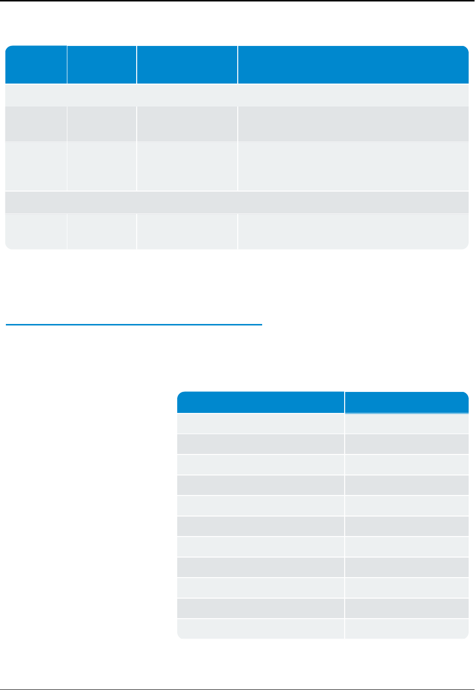
Cable Type Neptune Part
Number Coax Diameter Notes
LDF4-50A
8138-200 Coax Connector,
N Male
Mates with RMDC and antenna connectors
SureGround
Grounding Kit for 1/2 "
coax
AVA5-50
8138-190 Coax Connector, 7/16"
DIN Female
Used to connect to FSJ4 jumper cable
Table 27 – Connectors and Accessories (continued)
For the long-term protection of all RF connections, use the
appropriate Andrews weatherproofing kit (CommScope P/N
245171) on all coaxial connectors.
Antenna
General specifications for the supplied antenna are shown in the
table below.
Feature Specification
Neptune P/N 12896-001
Frequency Range 450-482 MHz
Maximum Input Power (Watts) 500
Gain 8.1 dBi (6 dBd)
Bandwidth < 1.5 VSWR 32 MHz
Vertical Beamwidth (-3 db) 20 degrees
Lightning Protection Direct ground
Termination N female
Overall Length 9.3 feet
Element Housing Length 6.8 feet
Support Pipe Diameter 2.5 inches
Table 28 – Antenna Specifications
70 R450™Rack Mount Data Collector Installation and Maintenance Guide
Appendix A: RF Antenna Installation

Feature Specification
Support Pipe Length 26 inches
Wind Load Area 1.61 square feet
Rated Wind Velocity 225 MPH
Weight 30 lbs
Mounting Hardware Included DB365 clamps
Table 28 – Antenna Specifications (continued)
Requirements
lIf mounting the antenna on the side of a tower or other
supporting structure, mount it so that it is at least 5 feet away
from the structure. The components to offset the antenna are
specific to the installation and are not included with the RMDC
package.
lThe antenna is large so take care when hoisting it up a tower so
that it is not damaged.
lDo not attach the feed line to the antenna while hoisting it up the
tower or other supporting structure. Attach the feed line after
the antenna is in place.
lThere have been reports of damage to the antenna's N-type
connector where the center pin is bent and shorts out the
antenna system. Take care not to damage the connector.
System Certification
The Andrews antenna supplied with the RMDC is specified as
having a VSWR of 1.5:1 or better over the 450 - 470 MHz range.
Measuring VSWR at the RMDC must take into account losses in the
feed line. For instructions, see"Measuring the VSWR" on page61.
The easiest approach is to use return loss instead of VSWR. The
1.5:1 VSWR translates into a return loss of 13.98 dB. Refer to Table
30 on page73and Table 31 on page75 to assist with the
calculation.
It is recommended that the feed line be certified as a separate step.
This is best performed by putting a known amount of power into
one end of the cable and verifying that, after correcting for the
cable losses, the correct amount of power is output at the other
end.
R450™Rack Mount Data Collector Installation and Maintenance Guide 71
Appendix A: RF Antenna Installation
Power Measurement
Input Power
Return Loss VSWR1W 5W 10W
Reflected Power Reading
0.001 0.005 0.01 30.0 1.07
0.002 0.010 0.02 27.0 1.09
0.003 0.015 0.03 25.2 1.12
0.004 0.020 0.04 24.0 1.14
0.005 0.025 0.05 23.0 1.15
0.006 0.030 0.06 22.2 1.17
0.007 0.035 0.07 21.5 1.18
0.008 0.040 0.08 21.0 1.20
0.009 0.045 0.09 20.5 1.21
0.010 0.050 0.10 20.0 1.22
0.020 0.100 0.20 17.0 1.33
0.030 0.150 0.30 15.2 1.42
0.040 0.200 0.40 14.0 1.50
0.050 0.250 0.50 13.0 1.58
0.060 0.300 0.60 12.2 1.65
0.070 0.350 0.70 11.5 1.72
0.080 0.400 0.80 11.0 1.79
0.090 0.450 0.90 10.5 1.86
0.100 0.500 1.00 10.0 1.92
0.110 0.550 1.10 9.59 1.99
0.120 0.600 1.20 9.21 2.06
Table 29 – Power Measurement to Return Loss and VSWR
Conversion Table -Part I
72 R450™Rack Mount Data Collector Installation and Maintenance Guide
Appendix A: RF Antenna Installation
Input Power
Return Loss VSWR1W 5W 10W
Reflected Power Reading
0.130 0.650 1.30 8.86 2.13
0.140 0.700 1.40 8.54 2.20
0.150 0.750 1.50 8.24 2.26
0.160 0.800 1.60 7.96 2.33
0.170 0.850 1.70 7.70 2.40
0.180 0.900 1.80 7.45 2.47
0.190 0.950 1.90 7.21 2.55
0.200 1.000 2.00 6.99 2.62
Table 29 – Power Measurement to Return Loss and VSWR Con-
version Table -Part I (continued)
Input Power
Return Loss VSWR1W 5W 10W
Reflected Power Reading
0.20 1.05 2.10 6.78 2.69
0.22 1.10 2.20 6.58 2.77
0.23 1.15 2.30 6.38 2.84
0.24 1.20 2.40 6.20 2.92
0.25 1.25 2.50 6.02 3.00
0.26 1.30 2.60 5.85 3.08
0.27 1.35 2.70 5.69 3.16
0.28 1.40 2.80 5.53 3.25
Table 30 – Power Measurement to Return Loss and VSWR
Conversion Table -Part II
R450™Rack Mount Data Collector Installation and Maintenance Guide 73
Appendix A: RF Antenna Installation

Input Power
Return Loss VSWR1W 5W 10W
Reflected Power Reading
0.29 1.45 2.90 5.38 3.33
0.30 1.50 3.00 5.23 3.42
0.31 1.55 3.10 5.09 3.51
0.32 1.60 3.20 4.95 3.60
0.33 1.65 3.30 4.81 3.70
0.34 1.70 3.40 4.69 3.80
0.35 1.75 3.50 4.56 3.90
0.36 1.80 3.60 4.44 4.00
0.37 1.85 3.70 4.32 4.11
0.38 1.90 3.80 4.20 4.21
0.39 1.95 3.90 4.09 4.33
0.40 2.00 4.00 3.98 4.44
0.41 2.05 4.10 3.87 4.56
0.42 2.10 4.20 3.77 4.68
0.43 2.15 4.30 3.67 4.81
0.44 2.20 4.40 3.57 4.94
0.45 2.25 4.50 3.47 5.08
0.46 2.30 4.60 3.37 5.22
0.47 2.35 4.70 3.28 5.36
0.48 2.40 4.80 3.19 5.51
0.49 2.45 4.90 3.10 5.67
Table 30 – Power Measurement to Return Loss and VSWR Con-
version Table -Part II (continued)
74 R450™Rack Mount Data Collector Installation and Maintenance Guide
Appendix A: RF Antenna Installation
Coax Cable Loss
Coax Type FSJ4-50B LDF4-50A AVA5-50
Loss 100 ft. 2.31 dB 1.45 dB 0.744 dB
Length (ft.) Loss in dB
10 0.231 0.145 0.074
20 0.462 0.290 0.149
30 0.693 0.435 1.223
40 0.924 0.580 0.298
50 1.155 0.725 0.372
60* 1.386 0.870 0.446
70* 1.617 1.015 0.521
80* 1.848 1.160 0.595
90* 2.079 1.305 0.670
100* 2.310 1.450 0.744
110 2.541 1.595 0.818
120 2.772 1.740 0.893
130 3.003 1.885 0.967
140 3.234 2.030 1.042
150 3.465 2.175 1.116
160 3.696 2.320 1.190
170 3.927 2.465 1.265
180 4.158 2.610 1.339
190 4.389 2.755 1.414
200 4.620 2.900 1.488
210 4.851 3.045 1.562
*Acceptable range
Table 31 – Coax Cable Loss Table
R450™Rack Mount Data Collector Installation and Maintenance Guide 75
Appendix A: RF Antenna Installation
Coax Type FSJ4-50B LDF4-50A AVA5-50
Loss 100 ft. 2.31 dB 1.45 dB 0.744 dB
Length (ft.) Loss in dB
220 5.082 3.190 1.637
230 5.313 3.335 1.711
240 5.544 3.480 1.786
250 5.775 3.625 1.860
260 6.006 3.770 1.934
270 6.237 3.915 2.009
280 6.468 4.060 2.083
290 6.699 4.205 2.158
300 6.930 4.350 2.232
310 7.161 4.495 2.306
320 7.392 4.640 2.381
330 7.623 4.785 2.455
340 7.854 4.930 2.530
350 8.085 5.075 2.604
360 8.316 5.220 2.678
370 8.547 5.365 2.753
380 8.778 5.510 2.827
390 9.009 5.655 2.902
400 9.240 5.800 2.976
Table 31 – Coax Cable Loss Table (continued)
VSWRCalculation
Neptune recommends the following method of computing VSWR.
Taking the reading at the RMDC end of the feed line without
compensating for cabling losses can give a false impression of the
antenna and feed line performance.
76 R450™Rack Mount Data Collector Installation and Maintenance Guide
Appendix A: RF Antenna Installation

Using a Wattmeter and a Handheld 450MHz Radio
The recommended procedure is to:
lUse a handheld commercial grade transceiver that is tuned to
the RMDC's transmitter frequency.
lUse an inline wattmeter, such as a Bird Model 43 Wattmeter
with the appropriate element (slug) for the frequency range and
power output of the transceiver.
The Bird Model 43 Wattmeter uses elements to set the frequency
and power ranges that the meter reads. Be sure the wattmeter
element is a 400 - 1000 MHz model sized so that the forward
power reading is close to full scale. For a 5W output handheld, the
Bird 5E element is recommended. If the radio puts out more than
5W, a Bird 10E or higher power element can be required.
Complete the following steps to use a wattmeter and handheld to
calculate VSWR.
1. Connect the wattmeter and transceiver to the feed line in place
of the RMDC.
2. Measure both the forward and reflected power.
3. Find the return loss value using Table 29 on page72 and Table
30 on page73.
4. Find the loss attributed to the coax using Table 31 on page75
(based on the coax type and feed line length).
Use the following formula to calculate the adjusted return loss.
Return Loss (fromTable) - (2 x Cable Loss) = Corrected Return
Loss
5. Find the VSWR using Table 29 on page72 and Table 30 on
page73 using the Corrected Return Loss value.
6. Change the frequency on the handheld transceiver to the
RMDC's receive frequency.
7. Measure the power and calculate VSWR using the procedure
just used for calculating transmitter VSWR.
8. Record the VSWR values for both the transmit and receive
frequencies. For the antenna system to pass, both calculated
VSWR values must be less than 1.5.1.
R450™Rack Mount Data Collector Installation and Maintenance Guide 77
Appendix A: RF Antenna Installation
Using the AEA 140-525 Antenna Analyzer
To configure the analyzer, complete the following steps.
This procedure assumes that the analyzer has not been
configured prior to use.
1. Turn the analyzer ON.
2. Type the frequency: 46000.
3. Press Enter.
4. Use the width buttons to set the value next to WID to 20.
5. Set the reading to return loss by pressing F1 slowly three times.
The unit beeps each time.
Taking the Reading and Calculating VSWR
To take the reading and calculate VSWR, complete the following
steps.
1. Connect the analyzer to the feed line in place of the
RMDC.
2. Configure the analyzer using the preceding procedure.
Be sure that there is not a vertical line running through the
display in the plot area. If there is, press EXAM PLOT to clear it.
3. Allow 10 - 20 seconds for the analyzer reading to stabilize.
4. Press EXAM PLOT to freeze the display.
5. Using the FREQ arrows, move the cursor (the vertical line in the
middle of the screen) to the RMDC's frequency. (It moves to
within 100KHz of a frequency.)
6. Read the value next to RETL on the display. This is the return
loss value.
7. Find the loss attributed to the coax (based on the coax type and
feed line length) using Table 31 on page75.
8. Calculate the adjusted return loss using the following formula.
Return Loss (from Table 5) - (2 x Cable Loss) = Corrected
Return Loss.
78 R450™Rack Mount Data Collector Installation and Maintenance Guide
Appendix A: RF Antenna Installation

9. Find the VSWR using the Corrected Return Loss value in Table
29 on page72 or Table 30 on page73
10. Move the cursor to within 100KHz of the RMDC's receive
frequency.
11. Calculate the VSWR using the new return loss value.
12. Record both values. They must be less than 1.5.1 for the
antenna and feed line to pass the test.
General Installation Guidelines
This section provides general installation guidelines.
Unpacking
As with all precision electronic instruments, handle the RF 450
MHz antenna with care; however, no additional special handling is
required.
After unpacking the RF 450 MHz antenna, inspect it for damage. If
any parts of the R450 MHz antenna appear to be damaged or
prove to be defective upon installation, notify your Neptune sales
representative. If the unit or item requires reshipment, use the
original cardboard box and packing material.
In particular, check to be sure that the N-type connector at the base
of the antenna is not damaged. This is much easier to check while
the antenna is on the ground than after it is installed.
RF Antenna Installation Kit
The RF 450 MHz antenna (see Figure 52) and the basic accessories
are included with the RMDC. The mounting brackets that are
included are designed to mount on the top of a mast or similar
structure.
If the installation requires offsetting the antenna from the
supporting structure, an antenna standoff mounting bracket (see
Figure 51) can be ordered separately from another vendor.
Neptune does not sell it. Mounting the antenna with a standoff
bracket moves the antenna out away from the structure and
improves performance.
R450™Rack Mount Data Collector Installation and Maintenance Guide 79
Appendix A: RF Antenna Installation
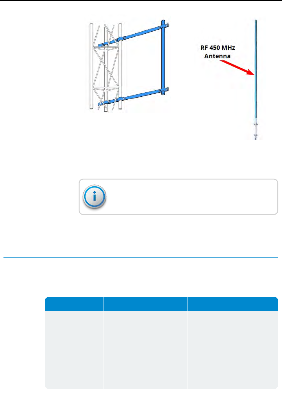
Figure 51 – Standoff Mounting Bracket Figure 52 – RF 450 MHz Antenna
Mounting the antenna using the standoff bracket will affect the
antenna pattern.
Tools and Materials
Table 32 shows the recommended tools and materials you need
to successfully install the RF antenna.
Item Description/Recommendation Use
Took Kit Contains standard tools
including:
lAssorted screwdrivers
(medium, flat-head)
lCordless electric drill /
assorted bits
lAdjustable wrench
lStandard socket wrench set
Various installation procedures
performed by the installer
Table 32 – Recommended Tools and Materials
80 R450™Rack Mount Data Collector Installation and Maintenance Guide
Appendix A: RF Antenna Installation
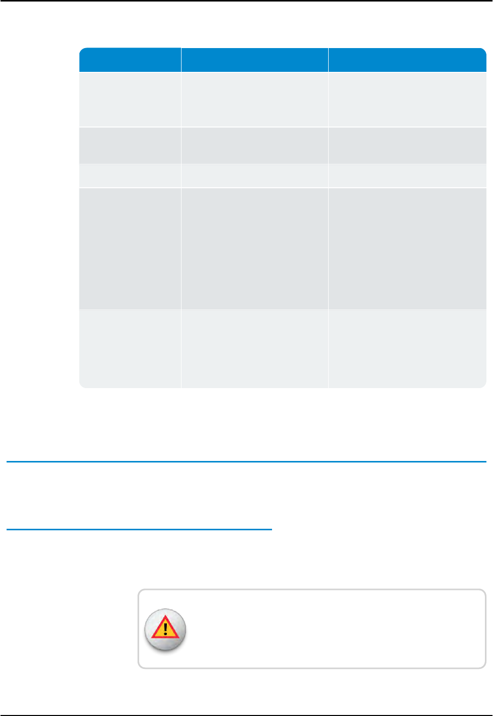
Item Description/Recommendation Use
lStandard box-end wrench set
lHammer
lChannel locks
UV-Stable Cable Ties 8" and 12"
(20.32 cm and 30.48 cm)
Secure coax cable
Cable Clips Various sizes Securing coax cable
Weatherizing Kit 3M - Scotch Weatherproofing Kit
(P/N: WK-101)
- or
Times Microwave P/N: WK-S-2
- or
CommScope P/N: 245171
Weatherproofing coax cable
connections
Electrical Tape Scotch®Heavy Duty Vinyl
Electrical Tape 22
- or
Scotch®Super 88
Weatherproofing coax cable
connections and other connections
as required
Table 32 – Recommended Tools and Materials (continued)
Installing the RF Antenna
This section contains theinstructions for the RF antenna
installation.
Mounting the RF 450 MHz Antenna
The RF 450 MHz antenna must be installed by professionals in
accordance with the FCC site license before you begin the
installation of the RMDC.
WARNING: Mounting and wiring the RF 450 MHz antenna must
be done by a trained professional. Be sure to subcontract this
work, so it is completed properly.
R450™Rack Mount Data Collector Installation and Maintenance Guide 81
Appendix A: RF Antenna Installation
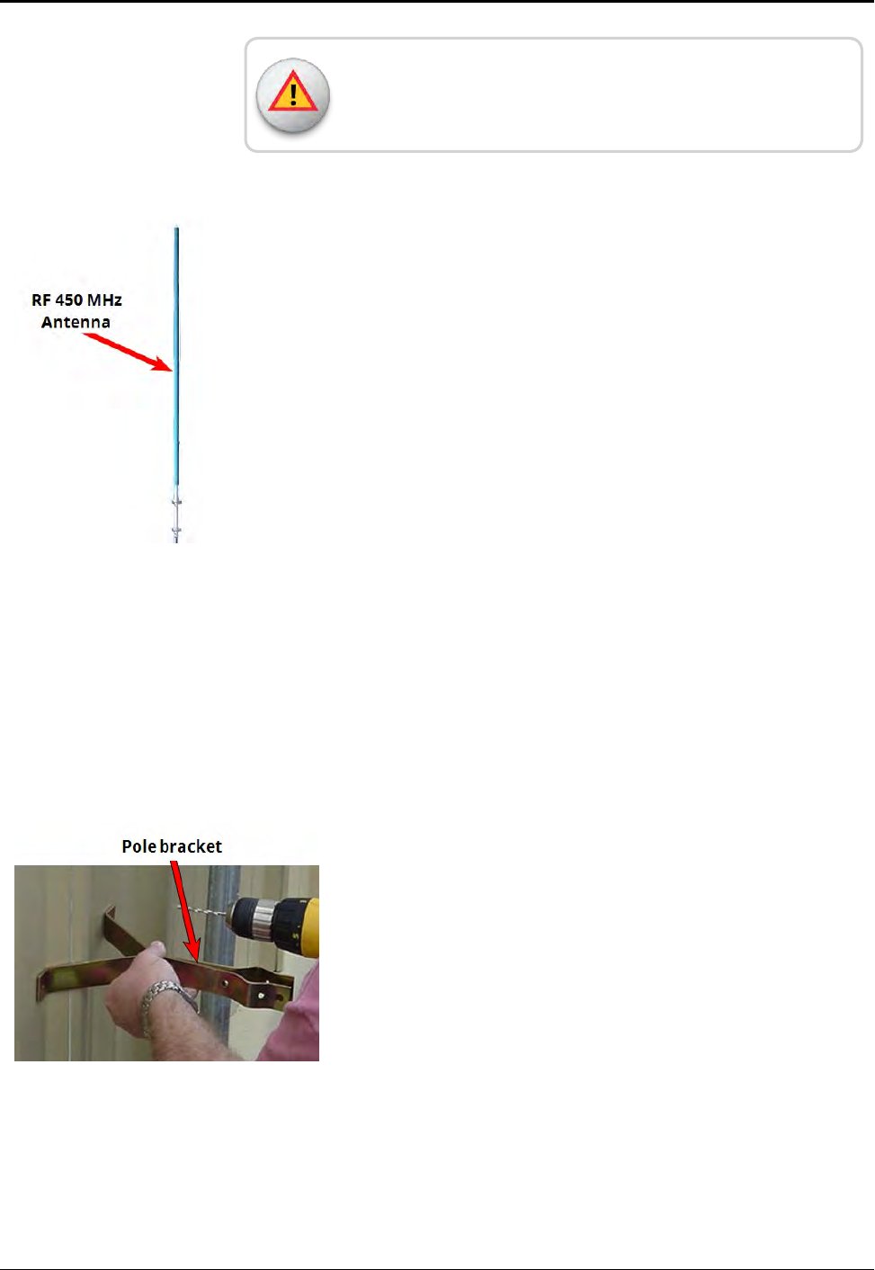
The subcontractor must check the cable, connectors, and the
antenna installation using the VSWR meter.
To mount the RF 450 MHz antenna, complete these steps.
1. Assemble the RF 450 MHz antenna according to the
instructions included with the antenna kit. See
"Troubleshooting" on page51.
2. Mount the antenna according to the instructions provided.
Use the mounting hardware included with the antenna kit.
3. Install the antenna in accordance with the FCC site license
(per the antenna mounting instructions contained in this
appendix).
4. Weatherize the antenna coaxial connector using the
weatherizing kit. See Table 32 on page80.
Figure 53 – RF 450 MHz Antenna to be Mounted
Mounting the Antenna Mast to the Building
With a wall-mount installation, it is necessary to mount the
RF 450 MHz antenna and cellular antenna on the exterior of the
building. Complete the following steps to mount the antenna mast
to the building. Use the manufacturer installation instructions
provided with mounting hardware.
Figure 54 – Securing the Pole Bracket
1. Use antenna pole brackets to install the pole to the building.
See Appendix A.
2. Pre-drill your holes for the first pole bracket.
3. Secure the pole bracket in one of the following ways. If
mounting to:
lA wood-constructed wall, use wood screws rated at
minimum of 20 pounds loading.
lSheet metal or masonry, use appropriate sheet metal
screws or masonry anchors rated at a minimum of 20
pounds loading.
82 R450™Rack Mount Data Collector Installation and Maintenance Guide
Appendix A: RF Antenna Installation
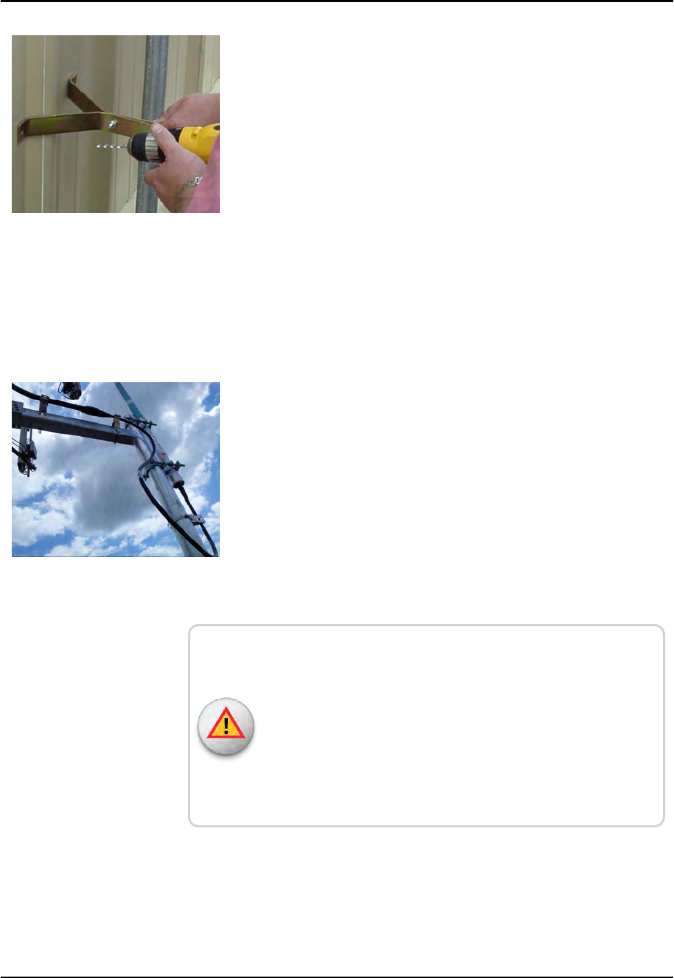
4. Place the antenna mast pole within the bracket.
5. Using a level to make sure the pole is vertical, line up a
second bracket a minimum of 2 feet from the bracket you
just installed.
6. Secure the second bracket similarly to the first one, following
steps 2 and 3.
7. Line up the pole in the two brackets. See Figure 55.
8. Secure the pole with the bolts provided.
Figure 55 – Lining Up Second Bracket
Attaching the RF 450 MHz Antenna Cable
To attach the RF 450 MHz antenna cable to the RMDC , complete
the following steps.
1. Locate the RF 450 MHz antenna cable that extends from the
RF 450 MHz antenna cable conduit. See Figure 56.
2. Connect the RF 450 MHz antenna cable to the RF 450 MHz
antenna connector located on the bottom of the antenna.
See Figure 56. Tighten the coaxial connector to:
lType N: 15 to 20 in-lb (1.7 - 2.30 N-m)
lType 7 - 16 DIN: 220 - 265 in-lb (25 - 30 N-m)
Figure 56 – RF 450 MHz Antenna Connection
WARNING: Give special consideration when the RMDC is
installed inside a building.
The screen (shield) of the coaxial cable must be connected to the
earth (grounded) at the entrance to the building. Be sure to do
this in accordance with applicable national electrical installation
codes (Section 820.93 of the National Electrical Code,
ANSI / NFPA 70).
R450™Rack Mount Data Collector Installation and Maintenance Guide 83
Appendix A: RF Antenna Installation
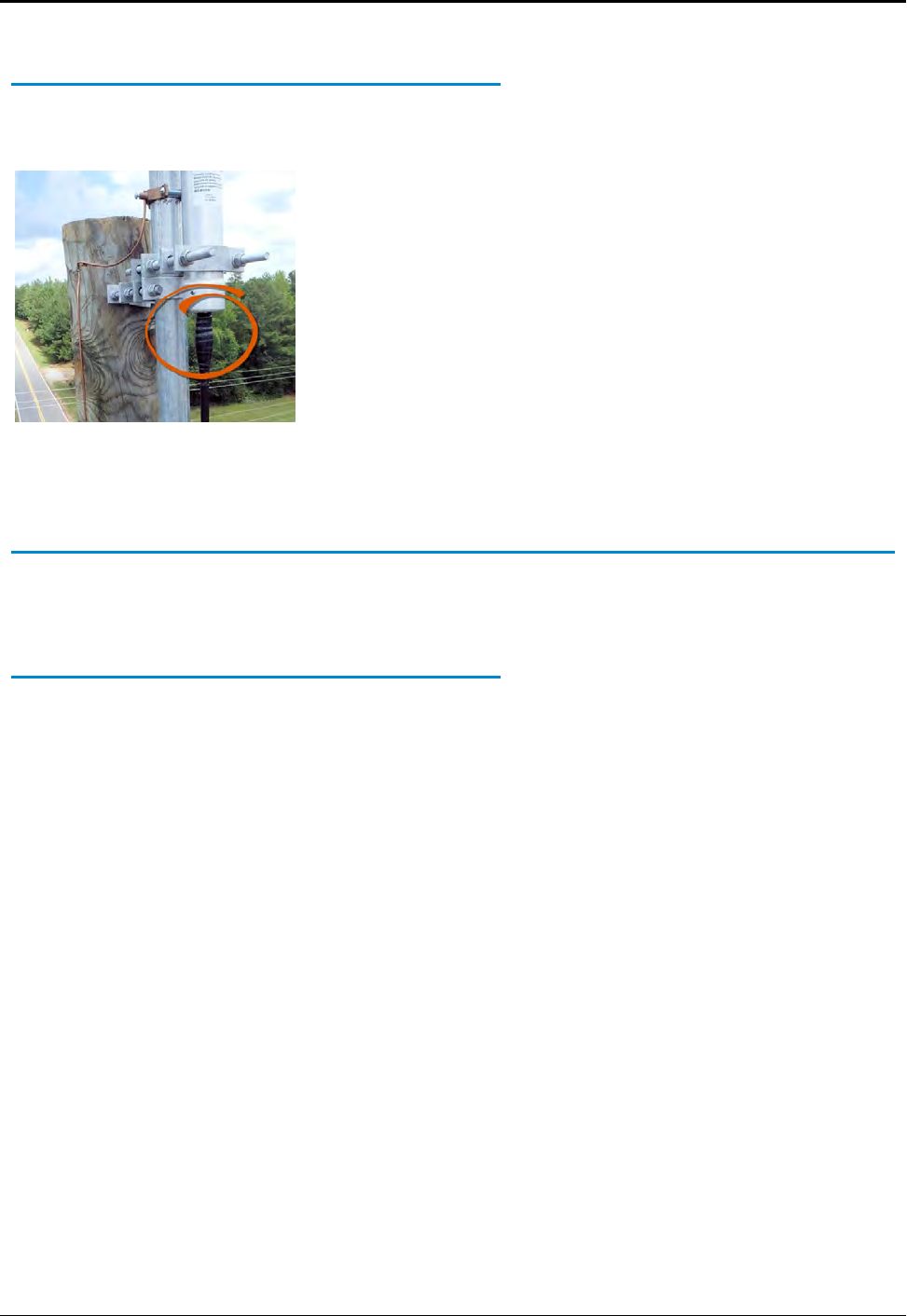
Weatherizing the Cable Connections
To weatherproof the cables using the Scotch Wireless WK-101 Kit
or equivalent, complete the following steps.
1. Using the weatherizing kit, start the tape at the top of the RF
antenna connection as illustrated in Figure 57.
2. Wrap the tape around the connection several times; slowly
work your way downward to weatherize your connection at
the base.
Figure 57 – Weatherizing the RF Antenna Connection
Troubleshooting the RF Antenna
This section provides a list of equipment needed to resolve
problems that can arise with your RF antenna.
Equipment Required
The following items are required to troubleshoot the
RMDC.
lKeys to access the site and open the R450 RMDC cabinet
lAdjustable wrench or set of open end wrenches to remove the
antenna N-type coaxial connector from inside of the R450
RMDC antenna surge arrestor.
lHandheld UHF (450 - 470 MHz) Radio
lBird Model 43 Wattmeter with appropriate slug or AEA
140 - 525 Antenna Analyzer
84 R450™Rack Mount Data Collector Installation and Maintenance Guide
Appendix A: RF Antenna Installation
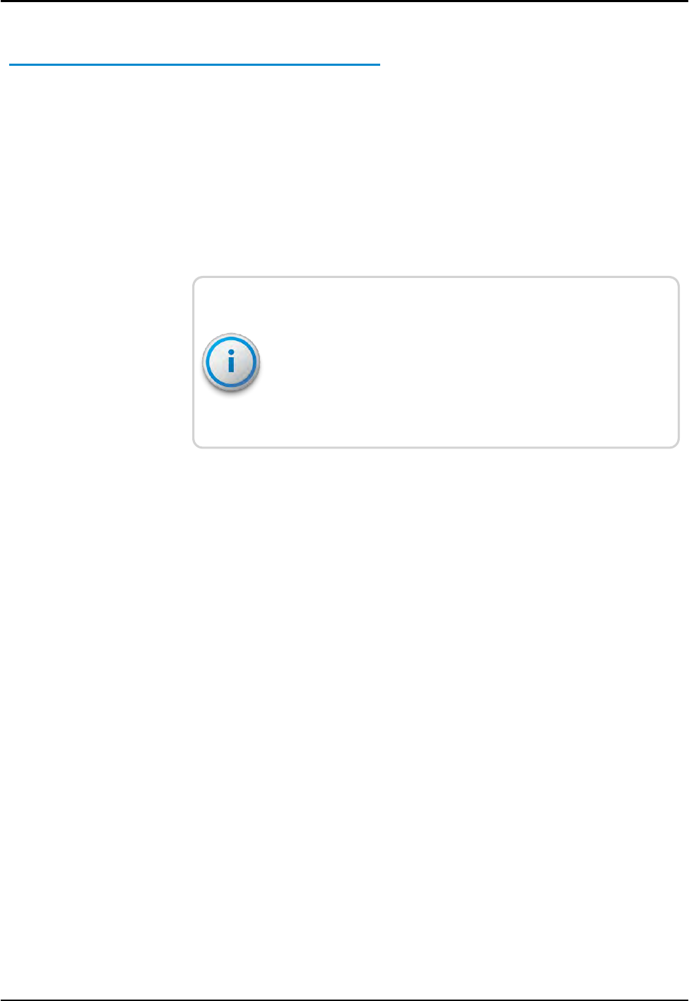
Testing the RF Antenna
To test the RFantenna, complete the following steps.
1. Remove the power from the R450 RMDC.
2. Open the R450 RMDC cabinet.
3. Use an open-end wrench or adjustable wrench to carefully
remove the coaxial cable assembly (with the N-type connector)
from the main antenna surge arrestor (located inside the
R450 RMDC cabinet at the bottom).
4. Go to "VSWRCalculation" on page76
If using the power measurement method for the VSWR
calculation, you cannot use the R450 RMDC's transmitter to
certify the antenna system. The transmitter only transmits short
packets approximately 50 ms in length, so taking an accurate
reading of forward or reflected power cannot be done with
standard equipment.
5. If the VSWR does not meet specifications, disconnect the RF
antenna feed cable (with the N-type connector) that is located
under the R450 RMDC cabinet.
Repeat the VSWRcalculation procedure on the RF antenna and
feed cable.
If the VSWR meets specifications, the problem may be a bad or
damaged antenna surge arrestor. Contact Neptune Customer
Support to return the R450 RMDC for repair.
R450™Rack Mount Data Collector Installation and Maintenance Guide 85
Appendix A: RF Antenna Installation

This page intentionally left blank.
Appendix A: RF Antenna Installation
86 R450™Rack Mount Data Collector Installation and Maintenance Guide
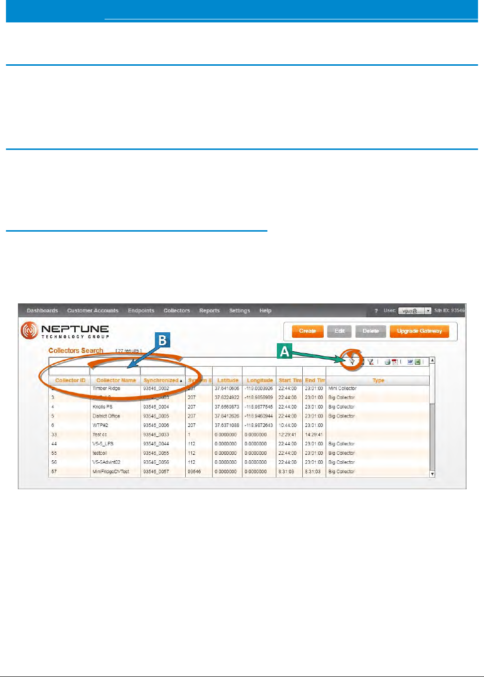
R450™Rack Mount Data Collector Installation and Maintenance Guide 87
Appendix B: USB Flash Drive Configuration for RMDC
Overview
This appendix provides information and the steps for creating a
R450™ Rack Mount Data Collector (R450 RMDC) and configuring the USB flash
drive using the N_SIGHT®PLUS host software.
Creating a Collector
The Collector tab in the N_SIGHT PLUS host software provides valuable information
about the R450 RMDC in your R450™ System. On this tab you can search for or
create an R450 RMDC.
Searching for Collectors
To locate an RMDC, complete the following steps.
1. Click Search Collectors on the Collector tab.
The following page appears.
Figure 58 – Collector Search
2. Click the Filter button. See Figure 58.
Three search fields appear. See Figure 58:
lCollector ID
lCollector Name
lSynchronized User
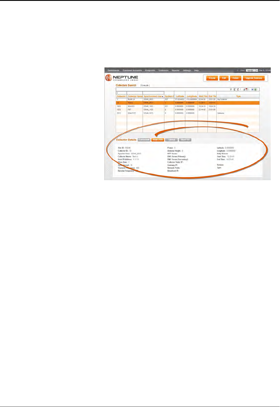
3. Type all or part of the search criteria in the search field.
Everything matching your search criteria appears in the
collector list on the Collector tab.
4. Select a collector and the detailed information for the collector
appears in the lower-half of the page. See Figure 59.
Figure 59 – Collector Search Results
5. Select one of the following options.
lCreate, to create another RMDC.
lEdit, to edit information for the selected RMDC.
lDelete, to delete the selected RMDC.
lBuild a USB, to build a drive for the RMDC.
88 R450™Rack Mount Data Collector Installation and Maintenance Guide
Appendix B: USB Flash Drive Configuration for RMDC
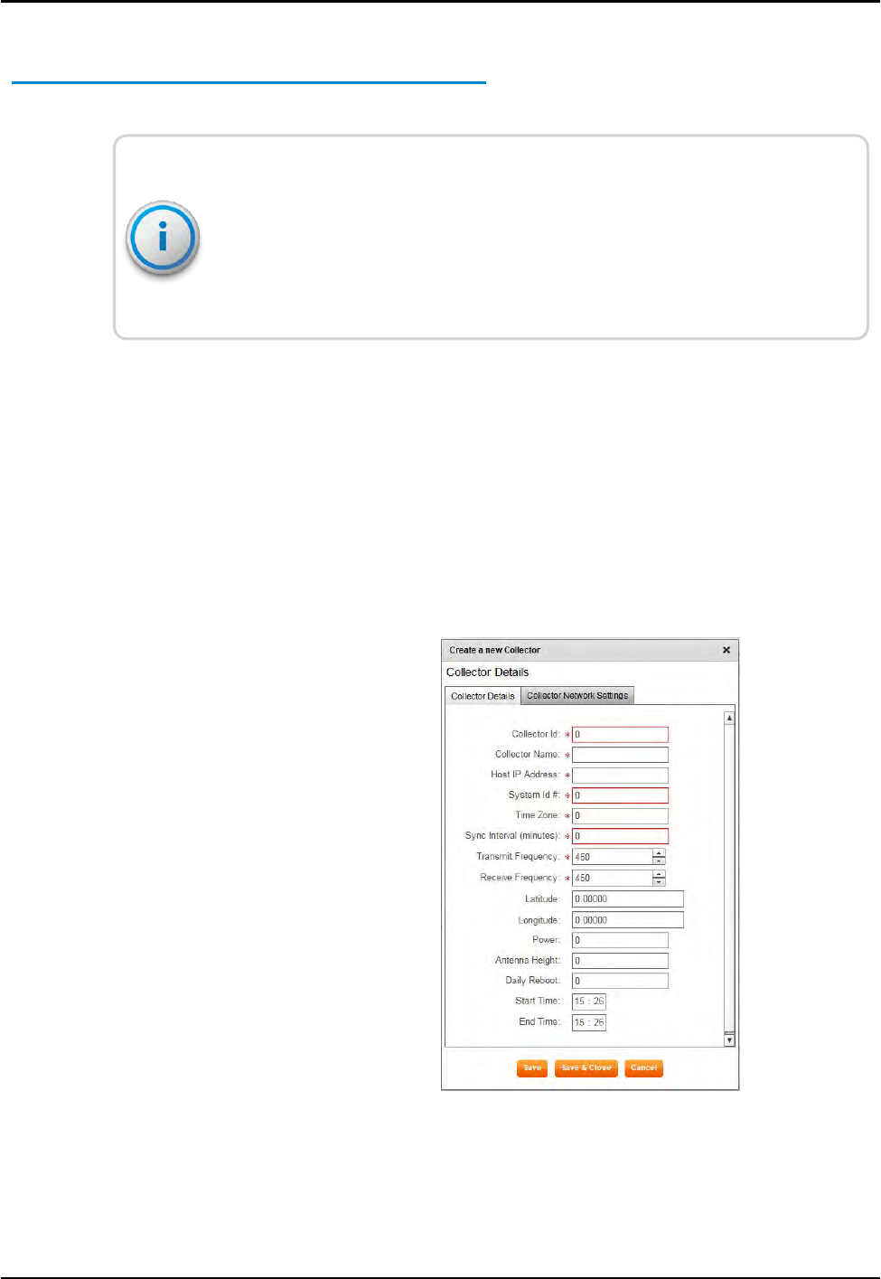
Creating a New Collector
On this tab, remember the following:
lAll fields with an *are required.
lAll white fields are available fields.
lAll fields with gray text are read-only fields.
To create a new RMDC, complete the following steps.
1. Open the N_SIGHT PLUS host software on the PC.
2. Select the Collector tab, and then click Create Collector.
The Create a New Collector window appears similar to Figure
60 on page 89. The Collector Details tab is the default tab
displayed. All required fields display a
red *.
Figure 60 – Create a New Collector Window
R450™Rack Mount Data Collector Installation and Maintenance Guide 89
Appendix B: USB Flash Drive Configuration for RMDC

Field Description
Collector ID Indicates the unique identifier for the data collector which can be a
street, location, or a neighborhood.
Collector Name Indicates the name of the data collector, for example the street,
neighborhood, tower name, and so forth.
Host IP Address Indicates the static IP address for the host database.
System ID # Indicates the system identification number.
Time Zone Indicates the unique identifier for the time zone in which the
RMDC is located; offset is fromUTC: Atlantic Time is -4; Eastern
Time is -5; and so forth.
Sync Interval
(minutes)
Indicates, in number of minutes, the time between
synchronizations between the collector and the database. Usually
it is 60 minutes for a cellular system, and 30 minutes for an
Ethernet system.
Transmit
Frequency
Indicates the frequency used to transmit data.
Receive
Frequency
Indicates the frequency used to receive data.
Latitude Indicates the actual latitude of the RMDC.
Longitude Indicates the actual longitude of the RMDC.
Power Indicates the power used by the RMDC.
Antenna Height Indicates the actual height of the RF antenna.
Daily Reboot Indicates if the RMDC requires a daily reboot.
Start Time Indicates the beginning time in hh:mm format for the quiet time
period when the RMDC is not transmitting or receiving.
End Time Indicates the ending time in hh:mm format for the quiet time
period when the RMDC is not transmitting or receiving.
Table 33 – Collector Details
90 R450™Rack Mount Data Collector Installation and Maintenance Guide
Appendix B: USB Flash Drive Configuration for RMDC
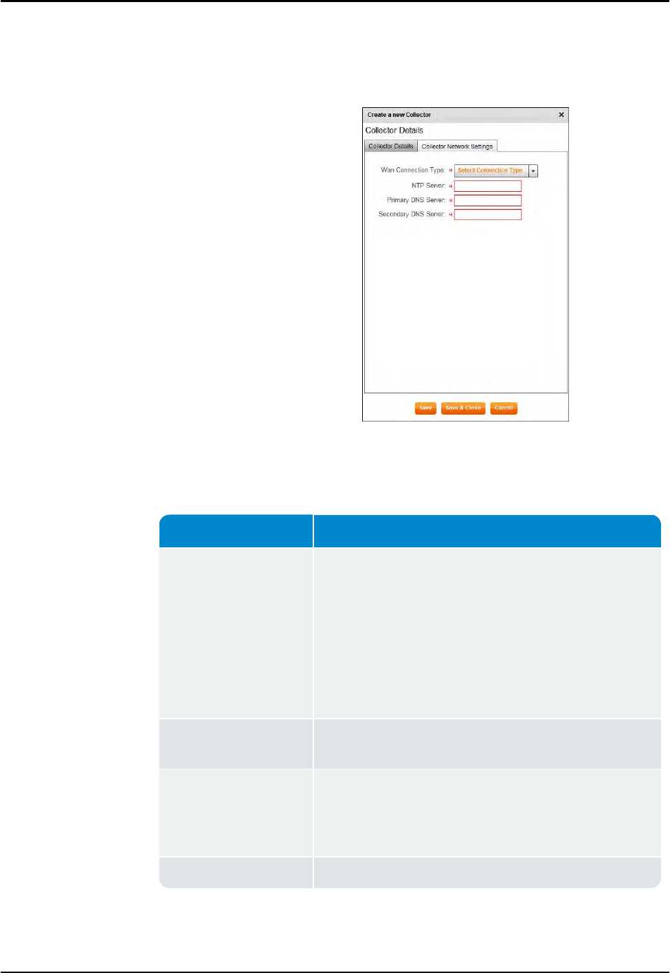
3. Complete all the required and available information that
applies, and then click Save.
The Collector Network Settings tab appears similar toFigure 61.
Figure 61 – Collector Network Setting Tab
Field Description
WAN Connection Type Indicates the type of Wide Area Network (WAN) used by the
RMDC. The options include the following:
lCellular
lCellular_Ethernet
lNetwork_DHCP
lNetwork_Static_IP
lMobile
NTP Server Indicates a server that uses NTP (Network Time Protocol) to
keep the clock accurate.
Primary DNS Server Indicates the primary server, the first DNS (Domain Name
System) server queried when resolving a server name. You
can supply the name rather than the IPaddress, for
example, Chicago rather than 10.10.10.10.
Secondary DNS Server Indicates the second DNS server.
Table 34 – Collector Network Settings
On this tab, remember the following:
R450™Rack Mount Data Collector Installation and Maintenance Guide 91
Appendix B: USB Flash Drive Configuration for RMDC
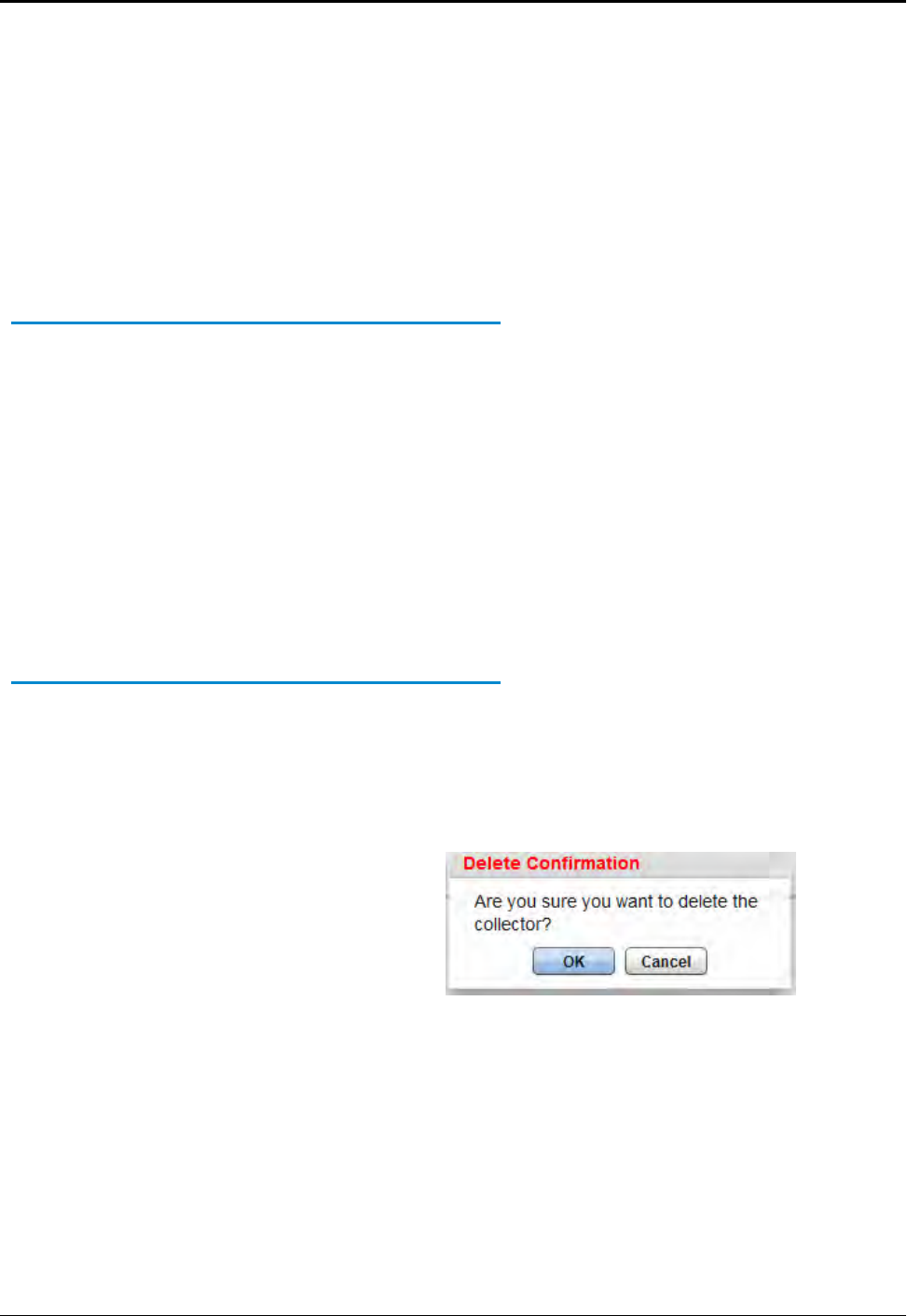
lAll fields with an *are required.
lAll white fields are available fields.
lAll fields with gray text are read-only fields.
4. Complete all the fields (on this tab, all fields are acquired), and
then click Save.
The new RMDC appears in the list of R450 DCs on the Collector
tab, and the detail appears in the lower half of the page.
Editing Collector Information
To edit information for an RMDC, complete the following steps.
1. On the Collector tab, select the RMDC for which you want to
edit the information.
The Edit Collector window appears with the existing
information for the collector.
2. Edit the appropriate information on both the Collector Details
tab and the Collector Network Settings tab.
3. Click Save to display and save the new information for the
collector.
Deleting a Collector
To delete a collector, complete the following steps.
1. On the Collector tab, select the collector you want to delete.
2. Click Delete.
A delete confirmation message appears similar to the following.
Figure 62 – Delete Confirmation Dialog Box
3. Click OK.
The RMDC is now deleted from the list of collectors on the
Collector tab.
92 R450™Rack Mount Data Collector Installation and Maintenance Guide
Appendix B: USB Flash Drive Configuration for RMDC
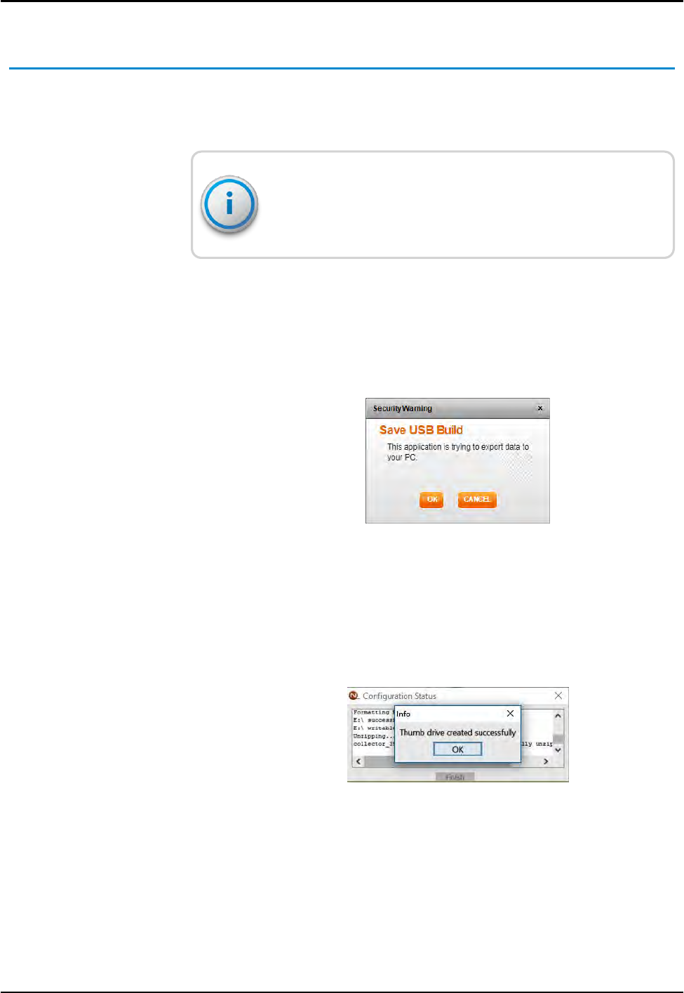
Building a USB Drive for Collector Configuration
This feature adds the ability to build a USB drive. It can be inserted
into a replacement collector for automatic configuration in order to
mimic an old collector.
R450 Collector configuration application must be installed on a
local PC to extract files to the USB drive. Make sure only the
desired USB drive is inserted into the computer.
To add a USBdrive, complete the following steps.
1. Select the RMDC from the Collector tab to uploaddata to the
USBdrive.
2. Click Build USB.
A confirmation message appears similar to the following.
Figure 63 – Save USB Build
3. Click OKto build the drive.
4. Double-click the downloaded file (*.ntg).
The application formats and extracts files to the USBdrive. A
message similar to the following appears.
Figure 64 – Thumb Drive Created
R450™Rack Mount Data Collector Installation and Maintenance Guide 93
Appendix B: USB Flash Drive Configuration for RMDC

This page intentionally left blank.
Appendix B: USB Flash Drive Configuration for RMDC
94 R450™Rack Mount Data Collector Installation and Maintenance Guide
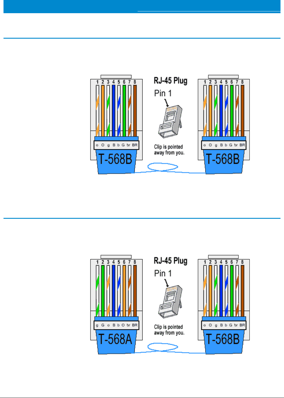
R450™Rack Mount Data Collector Installation and Maintenance Guide 95
Appendix C: Ethernet Termination
RJ-45 Straight-Through Ethernet Cable
For most installations, use the straight-through Ethernet cable. Terminate the
Ethernet cable according to the diagram below using the T-568B wiring standard
for both ends. Usually the end is already pre-terminated to the switch or hub.
Figure 65 – Straight-Through Ethernet Cable
RJ-45 Crossover Ethernet Cable
For some installations, a crossover Ethernet cable is required. If you require a cable
to connect two Ethernet devices directly together without a hub or when you
connect two hubs together, you need to use a crossover cable instead.
Figure 66 – RJ-45 Crossover Ethernet Cable

Determining if You Need a Crossover Cable
One method of determining if you need a crossover cable is to
plug the Ethernet cable from the hub or modem into your laptop
computer's Ethernet port. If the laptop computer can
communicate through the Ethernet port, then the site probably
requires a crossover Ethernet cable to be compatible with the
RMDC.
Symbol Wire Color
o White with orange stripe
O Solid orange
g White with green stripe
B Solid blue
b White with blue
G Solid green
br White with brown stripe
BR Solid brown
Table 35 – Cable Color Code Table
96 R450™Rack Mount Data Collector Installation and Maintenance Guide
Appendix C: Ethernet Termination
R450™Rack Mount Data Collector Installation and Maintenance Guide 97
Appendix D: Cellular Antenna Coax Cable
This appendix provides information about the cellular antenna coax cable.
Cellular Antenna Coax Cable Recommendations
Some installations require a longer coax cable for the cellular antenna connection.
In these instances, you can order longer pre-terminated coax cable assemblies
from Neptune. Refer to the coax cable recommendations in Table 36.
The coax cables are available in various lengths with N-male (plug), 50 ohm,
connectors terminated on each end. In addition, heat shrink tubing is applied to
both ends for added weatherproofing. However, the weatherproofing wrap (for
example 3M Weatherproofing Kit P/N: WK-101) is still required after you make the
final connection.
Coax Cable
Length (ft.) Coax Cable Type Neptune P/N
(if applicable)
6 Times Microwave LMR-195 10046-112
8 Times Microwave LMR-195 10046-113
10 Times Microwave LMR-400-UF 13090-001
20 Times Microwave LMR-400-UF 13090-002
30 Times Microwave LMR-400-UF 13090-003
40 Times Microwave LMR-400-UF 13090-004
Table 36 – Coax Cable Recommendations for Cellular Antenna

This page intentionally left blank.
Appendix D: Cellular Antenna Coax Cable
98 R450™Rack Mount Data Collector Installation and Maintenance Guide
R450™Rack Mount Data Collector Installation and Maintenance Guide 99
Appendix E: Strut Clamp Recommendations
Use the strut clamps to mount the R450™ Rack Mount Data Collector (R450 RMDC)
and UPS to Schedule 40 or Schedule 80 galvanized steel pipe. You can purchase
strut clamps from local electrical suppliers. A quantity of two per unit is required.
Table 37 shows some general recommendations for stainless steel (304) strut
clamps.
Inside Diameter (ID)
Clamp (inch)
For SCH 40/SCH 80
steel pipe size (inch)
Manufacturer P/N
(stainless steel)
2 3/8" 2" McMaster-Carr 3115T47
2 7/8" 2.5" McMaster-Carr 3115T48
3 1/2" 3" McMaster-Carr 3115T49
4" 3.5" McMaster-Carr 3115T51
4 1/2" 4" McMaster-Carr 3115T52
5 9/16" 5" McMaster-Carr 3115T53
6 5/8" 6" McMaster-Carr 3115T54
8 5/8" 8" McMaster-Carr 3115T66
Table 37 – Recommended Stainless Steel Strut Clamps
WARNING: Do not mount the R450 RMDC or UPS to steel pipe that is smaller
than 2 inches in diameter.

This page intentionally left blank.
Appendix E: Strut Clamp Recommendations
100 R450™Rack Mount Data Collector Installation and Maintenance Guide

Glossary
A
ALM
Alarm indicator.
AMI
Advance Metering Infrastructure. System that captures, stores, and provides to the utility at
frequent intervals detailed consumption and other information, such as, usage, leak, and flow
status, in order to support advanced applications. These data can then be used to support a
consumer portal. Furthermore, the mass of data generated by the system can feed an
advanced Analects system to convert it into actionable information that supports the efficient
management of the utility.
AMR
Automatic Meter Reading. The automated process of reading meters.
ANSI
American National Standards Institute.
APN
Access Point Name.
B
ballast
Heavy material used to secure the stability of the equipment stand. For the R450 System,
concrete blocks are used for the ballast.
R450™Rack Mount Data Collector Installation and Maintenance Guide 101

Glossary
C
CDMA
Code Division Multiple Access. A channel-access method used by various radio communication
technologies that allows multiple users to be connected over the same channel.
D
Data Collector
R450 Data Collector (R450 DC). The physical equipment that houses Neptune's N_SIGHT PLUS
host software. The R450 DC is a device that collects meter reading data from Neptune's
absolute encoder register interfacing with Neptune's R450 MIU and transmits the data for
collection. This unit receives the data for collection. This unit receives the data and stores data
to be downloaded through the host software.
dB
Decibels. The definition of the decibel is based on the measurement of power or the signal-to-
noise ratio.
dBm
Power ratio in decibels (dB) of the measured power referenced to one milliwatt.
DC
Direct Current.
DHCP
Dynamic Host Configuration Protocol.
DNS
Domain Name System.
DTF
Distance to Fault.
102 R450™Rack Mount Data Collector Installation and Maintenance Guide

Glossary
F
FCC
Federal Communications Commission.
FST
Field Service Tool.
G
GSM
Global System for Mobile communication. The most widely-used digital wireless telephony
technology.
I
IEEE
Institute of Electrical and Electronics Engineers.
IMEI
International Mobile Equipment Identifier.
in-lb
Inch-pound. A measurement of torque in the Imperial (American) system.
K
kA
Kiloampere. A measurement of electric current.
R450™Rack Mount Data Collector Installation and Maintenance Guide 103

Glossary
L
LED
Light Emitting Diode.
M
MDA
Mobile Directory Number.
MEID
Mobile Equipment Identifier.
MHz
Megahertz, a unit of frequency. One MHz is equal to one million hertz.
MIU
Meter Interface Unit.
MPH
Miles per Hour, as related to wind velocity.
ms
Milliseconds.
N
Nm
Newton meter or newton moment, a measurement of torque in the metric system.
NTP
Network Time Protocol.
104 R450™Rack Mount Data Collector Installation and Maintenance Guide

Glossary
O
ohm-out
Perform a continuity test with a digital multimeter or an ohm-meter.
P
P/N
Part Number.
PIN
Personal Identification Number.
R
R450 System
R450 System is a fixed network AMI system for targeted applications allowing a utility to
conduct meter reading operations automatically ensuring maximum collection of the data.
RMA
Return Material Authorization.
RSSI
Received signal strength indicator.
S
serial number
A unique identification number given to each product at the factory.
SIM
Subscriber Identification Module.
R450™Rack Mount Data Collector Installation and Maintenance Guide 105

Glossary
U
UPS
Uninterruptible Power Supply.
V
VAC
Volts Alternating Current.
VSWR
Voltage Standing Wave Ratio. The ratio of the amplitude of a partial standing wave at an
antinode (maximum) to the amplitude at an adjacent node (minimum) in an electrical
transmission line.
W
WAN
Wide Area Network.
106 R450™Rack Mount Data Collector Installation and Maintenance Guide

Index
A
AC-power box 29
AC connections 38
accessories, antenna 12
activating R450 RMDC 29
alarms, configuration packet 34
ALM 61
ambient noise 6
amplifiers 6
antenna 3, 12
analyzer 78
cable, RF 450 MHz 17, 25
cellular 8, 20
commercial broadcast 6
connection 17
connector 62
external 3
mast 66
mounting 65
placement 5
RF 450 MHz 28, 66
APN 31
AWG 18
B
backhaul 2, 4, 56
base connection 22
battery
AGM 38
charger 38
safety checklist 41
type 39
build USB 93
C
cable
attaching 17
AVA5-50 68
clips 81
conduit 17
guidelines 68
Heliax 68
ties 81
CalAmp Vanguard 29, 56, 59
calculation, VSWR 76
carrier 30
CDMA 31
CEC 22
cell connection 30
R450™Rack Mount Data Collector Installation and Maintenance Guide 107
Index

Index
cellular 22
antenna 19-20
modem 2, 7, 29
modem, connectivity 59
service provider 31
CIS 1
coax
cable 13, 18, 20-21
hoisting grips 13
coax cable loss 75
collector configuration, USB 93
collector monitor 34
color code, cable 96
communication 5
compliance 5
components 2
configuration, PC notebook 52
configuring
cellular modem 29
collector, USB flash drive 32
connecting
Ethernet 26
UPS 45
corrected return loss 77-78
CPU board 32-33, 53
crossover cable, Ethernet 95
customer support 64
D
DC connections 38
diagnostics, UPS 49
dimensions 39
disconnect switch 29
E
electrical specifications 11
email 35
environmental conditions 11
equipment, proper operation 5
Ethernet 2, 4, 26, 60
external antenna 3
F
FCC 1, 82
feed-in connection 22
feed line 6, 67
footprint 11
frequencies 1
FST 34, 51
G
general description 1
ground
lug 18
wire 18
grounding 21, 66
108 R450™Rack Mount Data Collector Installation and Maintenance Guide

Index
GSM 31
guidelines, installation 11
H
handheld 77
hazards 2
host database 52
host software 14, 34, 87
create new collector 89
deleting collector 92
editing collector 92
searching for collector 87
I
IMEI 8
improper installation 6
inclement weather 51
input current 43
installation 2, 33
interference 6
internal on-off switch 29
internet 52
K
kit
coax grounding 13, 18
installation 12
RF antenna installation 79
tool 13
UPS 8-9
weatherizing 13, 21, 81
L
licensed electrician 22
link integrity 33
M
magnet 14, 34, 60
main breaker switch 29
mast, antenna 3
materials and materials 13
MDN 31
measuring VSWR 61
mechanical specifications 11
MEID 8
Midland Radio 35
MIU, R450 1, 5, 14, 51, 60, 66
modem
cellular 2, 7, 29
Ethernet 18
WiFi 26
mounting
antenna mast 66, 82
bracket 38, 79
cellular antenna 25
components 3
hardware 8, 26
procedures 15
R450™Rack Mount Data Collector Installation and Maintenance Guide 109

Index
RF antenna 65, 81
wall 23
N
N-type connector 17
N_SIGHT PLUS 14, 34, 87
NEC 18, 22
network 33
noise level 6
O
Ohm multimeter 51
operating frequency 38
OTASP 31
output
connectors 46
current 38
P
part numbers
cable 69
connectors and accessories 69
parts list, cellular modem
cellular modem 8
performance
degrade 6
maintaining 7
optimizing 5
storm activity 7
pole
installation 4
mounting, UPS 37
propagation model 5
R
R450 RMDC 1, 6, 53, 61, 65, 81
R450 system 5, 7
radio 62
radio power 55
receiver 6-7
register, absolute encoder 1
requirements, feed line 67
return loss 72-73
RF antenna 65-66
attaching antenna cable 83
installation guidelines 79
installation kit 79
tools and materials 80
troubleshooting 84
unpacking 79
RJ45, external plug kit
external plug kit 9
RSSI 34
S
securing 36
serial port 61
service provider, cellular 8
110 R450™Rack Mount Data Collector Installation and Maintenance Guide

Index
servicing, UPS 47
SIM 8, 30
simulator, MIU 34
site, recommendation 66
socket wrench 20
specifications 11
electrical 11
environmental conditions 11
mechanical 11
UPS 38
spectrum analyzer 6
stable ties, UV 13
status LEDs
modem 57
UPS 47
storage 12
storm damage 52
strut clamp 8
surge
immunity, input 38
protector 68
survey 2, 6-7
synchronize 34, 61
system certification 71
T
termination, Ethernet 95
terrain 7
testing connections 33
tool kit 80
top strut channel 19
torque 18
transceiver 77
transfer time 38
transmitter 6
troubleshooting 51
U
UHF 61
unpacking 12
UPS 2, 22, 37
connecting 45
diagnostics 49
powering on 47
safety checklists 40
status LEDs 47
topology 38
weights 39
USB 32, 87
V
Verizon 31
voltage 47
input 38
output 38
VSWR 51, 63, 71, 78, 82
R450™Rack Mount Data Collector Installation and Maintenance Guide 111


IMR450™ RMDC 08.18 Part No. 12835-002 © Copyright 2006-2018,
Neptune Technology Group Inc. Neptune is a registered trademark of
Neptune Technology Group Inc.